EP4337447B1 - Extruderschnecke und verfahren zum herstellen derselben - Google Patents
Extruderschnecke und verfahren zum herstellen derselben Download PDFInfo
- Publication number
- EP4337447B1 EP4337447B1 EP22729039.2A EP22729039A EP4337447B1 EP 4337447 B1 EP4337447 B1 EP 4337447B1 EP 22729039 A EP22729039 A EP 22729039A EP 4337447 B1 EP4337447 B1 EP 4337447B1
- Authority
- EP
- European Patent Office
- Prior art keywords
- screw
- tension rod
- spline
- bore
- segments
- Prior art date
- Legal status (The legal status is an assumption and is not a legal conclusion. Google has not performed a legal analysis and makes no representation as to the accuracy of the status listed.)
- Active
Links
Images




Classifications
-
- B—PERFORMING OPERATIONS; TRANSPORTING
- B29—WORKING OF PLASTICS; WORKING OF SUBSTANCES IN A PLASTIC STATE IN GENERAL
- B29C—SHAPING OR JOINING OF PLASTICS; SHAPING OF MATERIAL IN A PLASTIC STATE, NOT OTHERWISE PROVIDED FOR; AFTER-TREATMENT OF THE SHAPED PRODUCTS, e.g. REPAIRING
- B29C48/00—Extrusion moulding, i.e. expressing the moulding material through a die or nozzle which imparts the desired form; Apparatus therefor
- B29C48/25—Component parts, details or accessories; Auxiliary operations
- B29C48/36—Means for plasticising or homogenising the moulding material or forcing it through the nozzle or die
- B29C48/50—Details of extruders
- B29C48/505—Screws
- B29C48/507—Screws characterised by the material or their manufacturing process
-
- B—PERFORMING OPERATIONS; TRANSPORTING
- B29—WORKING OF PLASTICS; WORKING OF SUBSTANCES IN A PLASTIC STATE IN GENERAL
- B29C—SHAPING OR JOINING OF PLASTICS; SHAPING OF MATERIAL IN A PLASTIC STATE, NOT OTHERWISE PROVIDED FOR; AFTER-TREATMENT OF THE SHAPED PRODUCTS, e.g. REPAIRING
- B29C48/00—Extrusion moulding, i.e. expressing the moulding material through a die or nozzle which imparts the desired form; Apparatus therefor
- B29C48/25—Component parts, details or accessories; Auxiliary operations
- B29C48/252—Drive or actuation means; Transmission means; Screw supporting means
-
- B—PERFORMING OPERATIONS; TRANSPORTING
- B29—WORKING OF PLASTICS; WORKING OF SUBSTANCES IN A PLASTIC STATE IN GENERAL
- B29C—SHAPING OR JOINING OF PLASTICS; SHAPING OF MATERIAL IN A PLASTIC STATE, NOT OTHERWISE PROVIDED FOR; AFTER-TREATMENT OF THE SHAPED PRODUCTS, e.g. REPAIRING
- B29C48/00—Extrusion moulding, i.e. expressing the moulding material through a die or nozzle which imparts the desired form; Apparatus therefor
- B29C48/25—Component parts, details or accessories; Auxiliary operations
- B29C48/256—Exchangeable extruder parts
- B29C48/2561—Mounting or handling of the screw
-
- B—PERFORMING OPERATIONS; TRANSPORTING
- B29—WORKING OF PLASTICS; WORKING OF SUBSTANCES IN A PLASTIC STATE IN GENERAL
- B29C—SHAPING OR JOINING OF PLASTICS; SHAPING OF MATERIAL IN A PLASTIC STATE, NOT OTHERWISE PROVIDED FOR; AFTER-TREATMENT OF THE SHAPED PRODUCTS, e.g. REPAIRING
- B29C48/00—Extrusion moulding, i.e. expressing the moulding material through a die or nozzle which imparts the desired form; Apparatus therefor
- B29C48/25—Component parts, details or accessories; Auxiliary operations
- B29C48/256—Exchangeable extruder parts
- B29C48/2564—Screw parts
-
- B—PERFORMING OPERATIONS; TRANSPORTING
- B29—WORKING OF PLASTICS; WORKING OF SUBSTANCES IN A PLASTIC STATE IN GENERAL
- B29C—SHAPING OR JOINING OF PLASTICS; SHAPING OF MATERIAL IN A PLASTIC STATE, NOT OTHERWISE PROVIDED FOR; AFTER-TREATMENT OF THE SHAPED PRODUCTS, e.g. REPAIRING
- B29C48/00—Extrusion moulding, i.e. expressing the moulding material through a die or nozzle which imparts the desired form; Apparatus therefor
- B29C48/25—Component parts, details or accessories; Auxiliary operations
- B29C48/256—Exchangeable extruder parts
- B29C48/2568—Inserts
- B29C48/25682—Inserts for screws
Definitions
- the invention relates firstly to a method for producing an extruder screw, wherein screw segments with radially protruding functional elements for conveying, mixing and/or kneading an extrudate, a through-hole in a longitudinal direction of the extruder screw and an inner spline running in the longitudinal direction in the through-hole are pushed one after the other onto an elongated cylindrical tie rod, cylindrical coupling pieces with an outer spline are inserted into the through-hole in such a form-fitting manner that they connect adjacent screw segments in a rotationally fixed manner and the screw segments are axially supported on a tip of the tie rod and clamped against the tip.
- the invention further relates to such an extruder screw.
- a spline is a longitudinal toothing of a cylinder surface, where the tooth flanks run parallel to the cylinder axis and transmit the torque between the shaft and the hub.
- Standardized splines with involute, spline and notch flanks are particularly cost-effective to produce.
- EN 10 2015 006 479 A1 a method and an extruder screw of the type mentioned above with longitudinally toothed coupling pieces pushed onto the tie rod between two screw segments on the front side, which engage in short grooves formed in the screw segments on the front side, is known.
- Such extruder screws are characterized by cheaper production and simplified maintenance.
- EN 44 44 370 A1 suggests screwing adjacent screw segments together through the end faces.
- US 2012/0135098 A1 suggests inserting keys into the end faces.
- EN 10 2008 028 289 A1 suggests gearing the end faces.
- the invention is based on the object of simplifying the production.
- the invention proposes that the through-hole has the spline over its entire length.
- the extruder screw according to the invention can be manufactured with screw segments that are available on the market in a wide variety for use in screw extruders with one-piece longitudinally toothed support shafts. The invention thus significantly simplifies the manufacture of the extruder screw.
- the screw segments are clamped against the tie rod, the coupling pieces have sufficient play in the longitudinal direction to avoid a double fit with undefined stress states in the screw segments even after the tie rod has been clamped.
- the play can be adjusted with simple, non-toothed pipe pieces between the coupling pieces.
- a drive segment with an external spline is pushed on last.
- Drive segments with a spline that matches the drive hub are known in the prior art.
- the drive segment can engage in a form-fitting manner with an external spline in a final worm segment like a coupling piece.
- the drive segment can engage in a final coupling piece like a worm segment with an internal spline.
- Such a drive segment can be used as a final Screw segment must be designed with corresponding functional elements for conveying, mixing and/or kneading.
- a clamping nut is finally screwed onto the tie rod at the rear end opposite the tip.
- the tie rod has an external thread at the rear end.
- the clamping nut then indirectly clamps the screw segments between the tip and the clamping nut.
- the clamping nut is not mechanically or thermally stressed: It is not in contact with the extrudate, no deposits form, it does not wear mechanically and is not heated up. If the extruder screw needs maintenance, it can therefore be easily loosened after the tension on the tie rod is released.
- the clamping nut has the spline teeth of the drive segment.
- the clamping nut is then mechanically secured during operation of the extruder screw by the corresponding internal teeth of the drive.
- the clamping nut is aligned with the spline of the drive segment by means of an alignment sleeve.
- the alignment sleeve prevents the clamping nut from being accidentally turned before the tension rod is stretched and the clamping nut indirectly clamps the screw segments against the tip.
- the tie rod is first stretched and then fixed in the stretched state. Unintentional torsional loading of the tie rod is thus avoided.
- the tension rod is hydraulically expanded.
- Hydraulic press cylinders are available in a wide variety and at low cost.
- the tension rod is fixed in the stretched state by means of the clamping nut.
- Fixing by means of the clamping nut is known in the prior art.
- a tensioning device is supported in the longitudinal direction on the screw segments.
- an additional support structure is not required.
- the tensioning device can be supported indirectly on the screw segments via a drive segment.
- the through-bore has the spline over its entire length.
- the extruder screw according to the invention is manufactured using a method according to the invention and is equally characterized by its advantages.
- the tip preferably has an internal spline corresponding to the spline of the coupling pieces.
- Such an extruder screw according to the invention effectively prevents the tip from accidentally twisting relative to the screw elements.
- Extruder screws according to the invention are used in a single, twin or multi-screw extruder in the same or counter-rotating manner.
- the extruder screw 1 has a tie rod 2.
- the tie rod 2 is made of structural steel and has a length 3 of 440 mm, a diameter 4 of 16.5 mm and a fine thread 7 (M16 ⁇ 0.5) with a length of 25 mm at the front end 5 and rear end 6.
- a tip 8 is first screwed onto the front end 5.
- the tip 8 has a length 9 of 44.5 mm, a diameter 10 of 39 mm and an axially protruding centering socket 11.
- the centering piece 11 is then further Figure 1b shown a first screw segment 12 with functional elements 13 (here: with a screw helix for conveying an extrudate by means of the extruder screw 1 in a screw extruder not shown) is placed on.
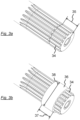
- the Figures 2a to 2c The worm segment 12 shown in detail has a length 13 and a diameter 14 of 60 mm each and a through hole 16 which has a spline 18 according to DIN 5480 over the entire length.
- the spline 18 has an inner tip circle diameter 19 of 29.5 mm, an outer tip circle diameter 20 of 32 mm and 24 teeth 21 with serrations.
- the coupling piece 22 is made of structural steel and has a standardized length 23 of 60 mm, an inner diameter of 16.5 mm, and on its outer cylinder surface 24 a spline 25 corresponding to the screw segment 12.
- the drive segment 26 has, over a length 27 of 209 mm , first of all functional elements 28 (here again a worm spiral) and an internal spline corresponding to the coupling pieces 22 adjacent to the worm segments 12 (here: again a worm spiral) and then a tube 29 with an internal diameter of 16.5 mm and an external diameter 30 which decreases from 39.6 mm in three stages 31, 32 to 34.3 mm and ends in an external spline 33.
- a clamping nut 34 with a length 35 of 20 mm is screwed on, which has the outer spline 33 of the drive segment 26.
- an alignment sleeve 36 with a length 37 of 20 mm and an outer diameter 38 of 39.5 mm is pushed over the clamping nut 34 and the drive segment 26.
- the alignment sleeve 36 has an internal toothing corresponding to the spline 18 and thus prevents the clamping nut 34 from twisting relative to the alignment sleeve 36.
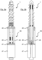
- the pre-assembled extruder screw 1 is tightened as shown in the Figures 5a /b shown a clamping device 39 is attached.
- the clamping device 39 is in the Figures 6a /b shown in detail.
- the clamping device 39 has two circular ring-shaped support rings 40, 41 with an outer diameter 42 of 85 mm, an inner diameter 43 of 38 mm and a thickness 44 of 10 mm , which are held by four support rods 45 at a distance 46 of 170 mm .
- the front support ring 40 is supported on the first step 31 of the drive segment 26 and thus indirectly on the screw segments 12.
- a hydraulic hollow piston cylinder 47 is attached to the rear support ring 41.
- the rear end 6 of the tie rod 2 has a bore 49 with an internal thread M10 (not shown), into which a pin 50 of the piston 48 is screwed.
- the tie rod 2 is then pulled out of the extruder screw 1 by means of the piston 48 with a load of 40 kN .
- the alignment sleeve 36 In the extended position, the alignment sleeve 36 is moved onto the drive segment 26 until it releases the clamping nut 34. The clamping nut 34 is then tightened by hand and secured again using the alignment sleeve 36. The piston 48 can now be relieved and the clamping device 39 can be dismantled.
- the tension of the tie rod 2 can be readjusted in the same way; if it is damaged or worn during operation, the extruder screw 1 can be easily dismantled in order to replace individual screw elements.
- a further extruder screw according to the invention corresponds to the first extruder screw 1, whereby, in contrast to the Figures 7a and 7b shown, the tip 51 has, instead of the centering nozzle 11, a blind bore 52 with the spline 18, into which a coupling piece 53 is first inserted.
Landscapes
- Engineering & Computer Science (AREA)
- Mechanical Engineering (AREA)
- Manufacturing & Machinery (AREA)
- Extrusion Moulding Of Plastics Or The Like (AREA)
Description
- Die Erfindung betrifft zunächst ein Verfahren zum Herstellen einer Extruderschnecke, wobei Schneckensegmente mit radial vorstehenden Funktionselementen zum Fördern, Mischen und/oder Kneten eines Extrudats, einer Durchgangsbohrung in einer Längsrichtung der Extruderschnecke und einer in der Längsrichtung verlaufenden inneren Passverzahnung in der Durchgangsbohrung nacheinander auf einen langgestreckten zylindrischen Zuganker aufgeschoben werden, in die Durchgangsbohrung zylindrische Koppelstücke mit einer äußeren Passverzahnung derart formschlüssig eingelegt werden, dass sie aneinander angrenzende Schneckensegmente verdrehfest verbinden und die Schneckensegmente an einer Spitze des Zugankers axial abgestützt und gegen die Spitze verspannt werden. Die Erfindung betrifft weiter eine solche Extruderschnecke.
- Als Passverzahnung wird eine Längsverzahnung einer Zylinderfläche bezeichnet, wobei die Zahnflanken parallel zur Zylinderachse verlaufen und das Drehmoment zwischen Welle und Nabe übertragen. Genormte Passverzahnungen mit Evolventen-, Keil- und Kerbflanken sind besonders kostengünstig herzustellen. Aus
DE 10 2015 006 479 A1 ist ein Verfahren und eine Extruderschnecke der vorstehend genannten Art mit stirnseitig jeweils zwischen zwei Schneckensegmenten auf den Zuganker aufgeschobenen längsverzahnten Koppelstücken bekannt, die in stirnseitig in die Schneckensegmente eingeformte kurze Nuten eingreifen. Gegenüber der über ihre gesamte Länge längsverzahnten Tragwelle im Hintergrund der Erfindung beispielsweise ausDE 77 01 692 U1 zeichnen sich solche Extruderschnecken durch eine preisgünstigere Herstellung und eine vereinfachte Wartung aus. - Die Herstellung der kurzen Nuten in Längsrichtung innen in den Schneckensegmenten ist technisch aber derart aufwändig und damit teuer, dass die bekannte Extruderschnecke sich am Markt nicht etablieren konnte.
-
DE 10 2016 011 978 A1 ,DE 37 14 506 A1 undEP 0 688 600 A1 schlagen im Hintergrund der Erfindung vor, Sackbohrungen in Stirnflächen der Schneckensegmente einzubringen und als Koppelstücke jeweils mehrere zylindrische Bolzen einzusetzen.DE 44 44 370 A1 schlägt vor, benachbarte Schneckensegmente durch die Stirnflächen miteinander zu verschrauben.US 2012/0135098 A1 schlägt vor, in den Stirnflächen Passfedern einzulegen.DE 10 2008 028 289 A1 schlägt vor, die Stirnflächen zu verzahnen. - Der Erfindung liegt die Aufgabe zugrunde, die Herstellung zu vereinfachen.
- Ausgehend von dem bekannten Verfahren wird nach der Erfindung vorgeschlagen, dass die Durchgangsbohrung über ihre gesamte Länge die Passverzahnung aufweist. Die erfindungsgemäße Extruderschnecke kann mit Schneckensegmenten hergestellt werden, die zur Verwendung in Schneckenextrudern mit einstückigen längsverzahnten Tragwellen in großer Vielfalt am Markt zur Verfügung stehen. Die Erfindung vereinfacht damit signifikant die Herstellung der Extruderschnecke.
- Erfindungsgemäß werden die Schneckensegmente gegen den Zuganker verspannt, die Koppelstücke weisen in der Längsrichtung ausreichend Spiel auf, um auch nach Verspannung des Zugankers eine Doppelpassung mit undefinierten Spannungszuständen in den Schneckensegmenten zu vermeiden. Bei Nutzung von Koppelstücken mit standardisierter Länge kann das Spiel mit einfachen, nicht verzahnten Rohrstücken zwischen den Koppelstücken eingestellt werden.
- Vorzugsweise wird in einem erfindungsgemäßen Verfahren zuletzt ein Antriebssegment mit einer äußeren Passverzahnung aufgeschoben. Antriebssegmente mit einer zur Antriebsnabe passenden Passverzahnung sind im Stand der Technik bekannt. Das Antriebssegment kann wie ein Koppelstück mit einer äußeren Passverzahnung in ein abschließendes Schneckensegment formschlüssig eingreifen. Alternativ kann das Antriebssegment wie ein Schneckensegment mit einer inneren Passverzahnung in ein abschließendes Koppelstück eingreifen. Ein solches Antriebssegment kann als abschließendes Schneckensegment mit entsprechenden Funktionselementen zum Fördern, Mischen und/oder Kneten ausgebildet sein.
- Vorzugsweise wird in einem erfindungsgemäßen Verfahren abschließend an dem der Spitze gegenüberliegenden hinteren Ende eine Spannmutter auf den Zuganker geschraubt. Der Zuganker weist in einem solchen erfindungsgemäßen Verfahren an dem hinteren Ende ein Außengewinde auf. Die Spannmutter verspannt dann mittelbar die Schneckensegmente zwischen der Spitze und der Spannmutter. Im Betrieb einer solchen Extruderschnecke ist die Spannmutter nicht mechanisch oder thermisch belastet: Sie steht nicht im Kontakt mit dem Extrudat, es bilden sich keine Ablagerungen, sie verschleißt nicht mechanisch und wird nicht aufgeheizt. Im Wartungsfall der Extruderschnecke lässt sie sich daher nach Entspannen des Zugankers leicht lösen.
- Vorzugsweise weist in einem solchen erfindungsgemäßen Verfahren die Spannmutter die Passverzahnung des Antriebssegments auf. Die Spannmutter ist dann im Betrieb der Extruderschnecke durch die entsprechende Innenverzahnung des Antriebs mechanisch gesichert.
- Weiter vorzugsweise wird in einem solchen erfindungsgemäßen Verfahren die Spannmutter mittels einer Ausrichthülse an der Passverzahnung des Antriebssegments ausgerichtet. Die Ausrichthülse vermeidet ein unbeabsichtigtes Verdrehen der Spannmutter, bevor eine Dehnung des Zugankers gelöst wird und die Spannmutter mittelbar die Schneckensegmente gegen die Spitze verspannt.
- Vorzugsweise wird in einem erfindungsgemäßen Verfahren zum Verspannen der Schneckensegmente der Zuganker zunächst gedehnt und anschließend in dem gedehnten Zustand fixiert. Eine unbeabsichtigte Torsionsbelastung des Zugankers wird so vermieden.
- Vorzugsweise wird in einem solchen erfindungsgemäßen Verfahren der Zuganker hydraulisch gedehnt. Hydraulische Presszylinder stehen variantenreich und preisgünstig zur Verfügung.
- Weiter vorzugsweise wird in einem solchen erfindungsgemäßen Verfahren der Zuganker mittels der Spannmutter in dem gedehnten Zustand fixiert. Die Fixierung mittels der Spannmutter ist im Stand der Technik bekannt.
- Weiter vorzugsweise wird in einem solchen erfindungsgemäßen Verfahren zum Dehnen des Zugankers eine Spannvorrichtung in der Längsrichtung an den Schneckensegmenten abgestützt. Bei Abstützung an den Schneckensegmenten ist eine zusätzliche Stützkonstruktion entbehrlich. Insbesondere kann die Spannvorrichtung mittelbar über ein Antriebssegment an den Schneckensegmenten abgestützt werden.
- Nach der Erfindung wird ausgehend von der bekannten Extruderschnecke vorgeschlagen, dass die Durchgangsbohrung über ihre gesamte Länge die Passverzahnung aufweist. Die erfindungsgemäße Extruderschnecke wird in einem erfindungsgemäßen Verfahren hergestellt und zeichnet sich gleichermaßen durch dessen Vorteile aus.
- Weiter weist vorzugsweise in einer solchen erfindungsgemäßen Extruderschnecke die Spitze eine der Passverzahnung der Koppelstücke entsprechende innere Passverzahnung auf. Eine solche erfindungsgemäße Extruderschnecke vermeidet wirksam ein unbeabsichtigtes Verdrehen der Spitze gegenüber den Schneckenelementen.
- Erfindungsgemäße Extruderschnecken kommen in einem Einzel-, Doppel- oder Mehrschneckenextruder gleich- oder gegenläufig zum Einsatz.
- Die Erfindung wird nachfolgend anhand von Ausführungsbeispielen erläutert. Es zeigen
- Fig. 1a-f
- Schritte zur Herstellung einer erfindungsgemäßen Extruderschnecke,
- Fig. 2a-c
- ein erfindungsgemäßes Schneckenelement der Extruderschnecke,
- Fig. 3a/b
- ein Detail der Extruderschnecke,
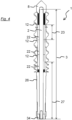
- Fig. 4
- einen Längsschnitt durch die Extruderschnecke,
- Fig. 5a/b
- die Extruderschnecke mit Spannvorrichtung,
- Fig. 6a/b
- die Spannvorrichtung im Detail, und
- Fig. 7a/b
- Schritte zur Herstellung einer weiteren erfindungsgemäßen Extruderschnecke
- Die (erst in
Figur 1f vollständig dargestellte) erfindungsgemäße Extruderschnecke 1 weist zunächst einen Zuganker 2 auf. Der Zuganker 2 besteht aus Baustahl und weist eine Länge 3 von 440 mm, einen Durchmesser 4 von 16,5 mm und am vorderen Ende 5 und hinteren Ende 6 jeweils ein Feingewinde 7 (M16 × 0,5) mit einer Länge von 25 mm auf. Wie inFigur 1a gezeigt, wird zunächst auf das vordere Ende 5 eine Spitze 8 geschraubt. Die Spitze 8 weist eine Länge 9 von 44,5 mm, einen Durchmesser 10 von 39 mm und einen axial vorstehenden Zentrierstutzen 11 auf. - Auf den Zentrierstutzen 11 wird weiter wie in
Figur 1b gezeigt ein erstes Schneckensegment 12 mit Funktionselementen 13 (hier: mit einer Schneckenwendel zum Fördern eines Extrudats mittels der Extruderschnecke 1 in einem nicht dargestellten Schneckenextruder) aufgesetzt. Das in denFiguren 2a bis 2c im Detail dargestellte Schneckensegment 12 weist eine Länge 13 und einen Durchmesser 14 von je 60 mm und eine Durchgangsbohrung 16 auf, die über die gesamte Länge eine Passverzahnung 18 nach DIN 5480 aufweist. Die Passverzahnung 18 weist einen inneren Kopfkreisdurchmesser 19 von 29,5 mm, einen äußeren Kopfkreisdurchmesser 20 von 32 mm und 24 Zähne 21 mit Kerbflanken auf. - Zwischen das Schneckensegment 12 und den Zuganker 2 wird wie in
Figur 1c gezeigt ein rohrförmiges Koppelstück 22 eingeschoben. Das Koppelstück 22 besteht aus Baustahl und weist eine standardisierte Länge 23 von 60 mm, einen Innendurchmesser von 16,5 mm, sowie auf seiner äußeren Zylinderfläche 24 eine dem Schneckensegment 12 entsprechende Passverzahnung 25 auf. - In derselben Weise werden wie in
Figur 1d dargestellt zwei weitere Schneckensegmente 12, je ein Koppelstück 22 und schließlich wie inFigur 1e dargestellt ein Antriebssegment 26 auf den Zuganker 2 geschoben. Zwischen den Koppelstücken 22 sind nicht dargestellte, nicht verzahnte Rohrstücke eingefügt, um das Spiel der Koppelstücke in Längsrichtung der Extruderschnecke 1 einzustellen. - Das Antriebssegment 26 weist auf einer Länge 27 von 209 mm anschließend an die Schneckensegmente 12 zunächst Funktionselemente 28 auf (hier: wiederum eine Schneckenwendel) und eine den Koppelstücken 22 entsprechende innere Passverzahnung und daran anschließend ein Rohr 29 mit einem Innendurchmesser von 16,5 mm und einem Außendurchmesser 30, der sich von 39,6 mm in drei Stufen 31, 32 auf 34,3 mm vermindert und in einer äußeren Passverzahnung 33 endet.
- Auf das Feingewinde 7 am hinteren Ende 6 des Zugankers 2 wird wie in
Figur 1f sowie im Detail in denFiguren 3a und 3b dargestellt eine Spannmutter 34 mit einer Länge 35 von 20 mm aufgeschraubt, die die äußere Passverzahnung 33 des Antriebssegments 26 aufweist. Die Vormontage abschließend wird eine Ausrichthülse 36 mit einer Länge 37 von 20 mm und einem Außendurchmesser 38 von 39,5 mm über die Spannmutter 34 und das Antriebssegment 26 geschoben. Die Ausrichthülse 36 weist eine der Passverzahnung 18 entsprechende Innenverzahnung auf und vermeidet so ein Verdrehen der Spannmutter 34 gegenüber der Ausrichthülse 36. - Zum Spannen des Zugankers 2 wird an der vormontierten Extruderschnecke 1 wie in den
Figuren 5a /b dargestellt eine Spannvorrichtung 39 angebracht. Die Spannvorrichtung 39 ist in denFiguren 6a /b im Detail dargestellt. - Die Spannvorrichtung 39 weist zwei kreisringförmige Stützringe 40, 41 mit einem äußeren Durchmesser 42 von 85 mm, einem inneren Durchmesser 43 von 38 mm und einer Dicke 44 von 10 mm auf, die von vier Stützstäben 45 in einem Abstand 46 von 170 mm gehalten werden. Der vordere Stützring 40 wird an der ersten Stufe 31 des Antriebssegments 26 und dadurch mittelbar an den Schneckensegmenten 12 abgestützt. An dem hinteren Stützring 41 ist ein hydraulischer Hohlkolbenzylinder 47 angebracht.
- Um einen Kolben 48 des Hohlkolbenzylinders 47 mit dem Zuganker 2 zu verbinden, weist das hintere Ende 6 des Zugankers 2 eine Bohrung 49 mit einem nicht dargestellten Innengewinde M10 auf, in das ein Zapfen 50 des Kolbens 48 eingeschraubt wird. Dann wird der Zuganker 2 mittels des Kolbens 48 mit einer Last von 40 kN aus der Extruderschnecke 1 herausgezogen.
- In der gelängten Stellung wird die Ausrichthülse 36 so weit auf das Antriebssegment 26 verschoben, dass sie die Spannmutter 34 freigibt. Dann wird die Spannmutter 34 handfest angezogen und mittels der Ausrichthülse 36 erneut gesichert. Nun kann der Kolben 48 entlastet und die Spannvorrichtung 39 demontiert werden.
- Bei einer Wartung der Extruderschnecke 1 nach einer vorgegeben Betriebsdauer kann die Spannung des Zugankers 2 in derselben Weise nachjustiert werden, bei Beschädigung oder Abnutzung im Betrieb kann die Extruderschnecke 1 leicht demontiert werden, um einzelne Schneckenelemente zu ersetzen.
- Eine nicht dargestellte weitere erfindungsgemäße Extruderschnecke entspricht der ersten Extruderschnecke 1, wobei abweichend wie in den
Figuren 7a und 7b gezeigt die Spitze 51 anstelle des Zentrierstutzens 11 eine Sackbohrung 52 mit der Passverzahnung 18 aufweist, in die zunächst ein Koppelstück 53 eingeschoben wird. -
- 1
- Extruderschnecke
- 2
- Zuganker
- 3
- Länge
- 4
- Durchmesser
- 5
- vorderes Ende
- 6
- hinteres Ende
- 7
- Feingewinde
- 8
- Spitze
- 9
- Länge
- 10
- Durchmesser
- 11
- Zentrierstutzen
- 12
- Schneckensegment
- 13
- Funktionselement
- 14
- Länge
- 15
- Durchmesser
- 16
- Durchgangsbohrung
- 18
- Passverzahnung
- 19
- innerer Kopfkreisdurchmesser
- 20
- äußerer Kopfkreisdurchmesser
- 21
- Zahn
- 22
- Koppelstück
- 23
- Länge
- 24
- Zylinderfläche
- 25
- Passverzahnung
- 26
- Antriebssegment
- 27
- Länge
- 28
- Funktionselement
- 29
- Rohr
- 30
- Außendurchmesser
- 31
- Stufe
- 32
- Stufe
- 33
- Passverzahnung
- 34
- Spannmutter
- 35
- Länge
- 36
- Ausrichthülse
- 37
- Länge
- 38
- Außendurchmesser
- 39
- Spannvorrichtung
- 40
- Stützring
- 41
- Stützring
- 42
- äußerer Durchmesser
- 43
- innerer Durchmesser
- 44
- Dicke
- 45
- Stützstab
- 46
- Abstand
- 47
- Hohlkolbenzylinder
- 48
- Kolben
- 49
- Bohrung
- 50
- Zapfen
- 51
- Spitze
- 52
- Sackbohrung
- 53
- Koppelstück
Claims (10)
- Verfahren zum Herstellen einer Extruderschnecke (1), wobeia. Schneckensegmente (12) miti. radial vorstehenden Funktionselementen (13) zum Fördern, Mischen und/oder Kneten eines Extrudats,ii. einer Durchgangsbohrung (16) in einer Längsrichtung der Extruderschnecke (1) undiii. einer in der Längsrichtung verlaufenden inneren Passverzahnung (18) in der Durchgangsbohrung (16) nacheinander auf einen langgestreckten zylindrischen Zuganker (2) aufgeschoben werden,b. in die Durchgangsbohrung (16) zylindrische Koppelstücke (22, 53) mit einer äußeren Passverzahnung (25) derart formschlüssig eingelegt werden, dass sie aneinander angrenzende Schneckensegmente (12) verdrehfest verbinden undc. die Schneckensegmente (12) an einer Spitze (8, 51) des Zugankers (2) axial abgestützt und gegen die Spitze (8, 51) verspannt werden,wobei die Durchgangsbohrung (16) über ihre gesamte Länge die Passverzahnung (18) aufweist.
- Verfahren nach dem vorgenannten Anspruch, dadurch gekennzeichnet, dass zuletzt ein Antriebssegment (26) mit einer äußeren Passverzahnung (33) aufgeschoben wird.
- Verfahren nach einem der vorgenannten Ansprüche, dadurch gekennzeichnet, dass abschließend eine Spannmutter (34) auf den Zuganker (2) geschraubt wird.
- Verfahren nach den Ansprüchen 2 und 3, dadurch gekennzeichnet, dass die Spannmutter (34) die Passverzahnung (33) des Antriebssegments (26) aufweist.
- Verfahren nach dem vorgenannten Anspruch, dadurch gekennzeichnet, dass die Spannmutter (34) mittels einer Ausrichthülse (36) an der Passverzahnung (33) ausgerichtet wird.
- Verfahren nach einem der vorgenannten Ansprüche, dadurch gekennzeichnet, dass zum Verspannen der Schneckensegmente (12) der Zuganker (2) zunächst vorzugsweise hydraulisch gedehnt und anschließend in dem gedehnten Zustand fixiert wird, vorzugsweise mittels der Spannmutter (34) gemäß Anspruch 3.
- Verfahren nach dem vorgenannten Anspruch, dadurch gekennzeichnet, dass zum Dehnen des Zugankers (2) eine Spannvorrichtung (39) in der Längsrichtung an den Schneckensegmenten (12) abgestützt wird.
- Extruderschnecke (1) mita. einem langgestreckten zylindrischen Zuganker (2),b. Schneckensegmenten (12), diei. radial vorstehende Funktionselemente (13) zum Fördern, Mischen und/oder Kneten eines Extrudatsii. eine Durchgangsbohrung (16) in einer Längsrichtung der Extruderschnecke (1), undiii. eine in der Längsrichtung verlaufende innere Passverzahnung (18) in der Durchgangsbohrung (16) aufweisen und an einer Spitze (8, 51) des Zugankers (2) axial abgestützt und gegen die Spitze (8, 51) verspannt sind,gekennzeichnet durchc. zylindrische Koppelstücke (22, 53) mit einer äußeren Passverzahnung (25), die in die Durchgangsbohrung (16) derart formschlüssig eingelegt sind, dass sie aneinander angrenzende Schneckensegmente (12) verdrehfest verbinden,wobei die Durchgangsbohrung (16) über ihre gesamte Länge die Passverzahnung (18) aufweist.
- Extruderschnecke nach dem vorgenannten Anspruch, dadurch gekennzeichnet, dass die Spitze (51) die innere Passverzahnung (18) aufweist.
- Schneckenextruder mit einer oder mehreren Extruderschnecken (1) nach dem vorgenannten Anspruch.
Applications Claiming Priority (2)
| Application Number | Priority Date | Filing Date | Title |
|---|---|---|---|
| DE102021112163.9A DE102021112163A1 (de) | 2021-05-10 | 2021-05-10 | Verfahren zum Herstellen einer Extruderschnecke und Schneckensegment |
| PCT/EP2022/061891 WO2022238186A1 (de) | 2021-05-10 | 2022-05-04 | Extruderschnecke und verfahren zum herstellen derselben |
Publications (3)
| Publication Number | Publication Date |
|---|---|
| EP4337447A1 EP4337447A1 (de) | 2024-03-20 |
| EP4337447B1 true EP4337447B1 (de) | 2024-08-14 |
| EP4337447C0 EP4337447C0 (de) | 2024-08-14 |
Family
ID=82016295
Family Applications (1)
| Application Number | Title | Priority Date | Filing Date |
|---|---|---|---|
| EP22729039.2A Active EP4337447B1 (de) | 2021-05-10 | 2022-05-04 | Extruderschnecke und verfahren zum herstellen derselben |
Country Status (5)
| Country | Link |
|---|---|
| US (1) | US20240140014A1 (de) |
| EP (1) | EP4337447B1 (de) |
| DE (1) | DE102021112163A1 (de) |
| ES (1) | ES2994246T3 (de) |
| WO (1) | WO2022238186A1 (de) |
Families Citing this family (3)
| Publication number | Priority date | Publication date | Assignee | Title |
|---|---|---|---|---|
| DE102024101964A1 (de) | 2024-01-24 | 2025-07-24 | Extruder Experts Gmbh & Co. Kg | Extruderschnecke und Verfahren zum Herstellen derselben |
| DE102024110958A1 (de) * | 2024-04-18 | 2025-10-23 | Ostschweizer Fachhochschule | Extruderwellenvorrichtung für einen gegenläufigen Doppelwellenextruder |
| DE102024121963A1 (de) | 2024-08-01 | 2026-02-05 | Leistritz Extrusionstechnik Gmbh | Extruderschnecke |
Family Cites Families (14)
| Publication number | Priority date | Publication date | Assignee | Title |
|---|---|---|---|---|
| DE7701692U1 (de) | 1977-01-21 | 1980-07-31 | Eickhoff-Kleinewefers Kunststoffmaschinen Gmbh, 4630 Bochum | Vorrichtung zum aufbereiten und strangpressen von thermoplastischen kunststoffen |
| DE3714506A1 (de) | 1987-04-30 | 1988-11-10 | Wilfried Schraufstetter | Formschluessige verbindung zweier koaxialer wellenteile, insbesondere hohlwellenteile |
| JPH081048Y2 (ja) * | 1991-10-30 | 1996-01-17 | 株式会社日本製鋼所 | 分割式スクリュ |
| JP2834405B2 (ja) | 1994-06-20 | 1998-12-09 | 株式会社神戸製鋼所 | 連続混練機 |
| DE4444370A1 (de) | 1994-12-14 | 1996-06-20 | Max Gutknecht | Vorrichtung zum thermischen, mechanischen, chemischen und/oder physikalischen Behandeln eines Produktes |
| DE102008028289B4 (de) | 2008-06-16 | 2021-07-15 | Leistritz Extrusionstechnik Gmbh | Extruderschnecke sowie Extruder umfassend mindestens eine solche Extruderschnecke |
| DE102010047597A1 (de) | 2010-10-05 | 2012-04-05 | Kraussmaffei Berstorff Gmbh | Vorrichtung zum Spannen von Extruderschneckensegmenten auf einem Dorn |
| US20120135098A1 (en) | 2010-11-30 | 2012-05-31 | Conor James Walsh | Extrusion Mixing Screw and Method of Use |
| DE112014006855B4 (de) | 2014-08-06 | 2024-05-16 | Entek Manufacturing, LLC | Extruderschneckenwellen-Ausrichtungsvorrichtung und -verfahren |
| DE102015006479A1 (de) | 2015-05-22 | 2016-11-24 | Reifenhäuser GmbH & Co. KG Maschinenfabrik | Schnecke zum Einsatz in einem Extruder sowie Extruder |
| DE102015012435A1 (de) | 2015-09-27 | 2017-03-30 | Entex Rust & Mitschke Gmbh | Planetwalzenextruder |
| DE102016011978A1 (de) | 2016-10-10 | 2018-04-12 | Reifenhäuser GmbH & Co. KG Maschinenfabrik | Schnecke zum Einsatz in einem Extruder und Extruder |
| KR101813409B1 (ko) | 2016-12-01 | 2017-12-28 | 유창공업 주식회사 | 압출기용 기어박스의 소켓형 스핀들 |
| CN112622221B (zh) * | 2020-12-03 | 2021-11-26 | 欧宝聚合物江苏有限公司 | 一种机筒螺杆机构 |
-
2021
- 2021-05-10 DE DE102021112163.9A patent/DE102021112163A1/de active Pending
-
2022
- 2022-05-04 EP EP22729039.2A patent/EP4337447B1/de active Active
- 2022-05-04 WO PCT/EP2022/061891 patent/WO2022238186A1/de not_active Ceased
- 2022-05-04 ES ES22729039T patent/ES2994246T3/es active Active
-
2023
- 2023-11-05 US US18/387,047 patent/US20240140014A1/en active Pending
Also Published As
| Publication number | Publication date |
|---|---|
| EP4337447A1 (de) | 2024-03-20 |
| DE102021112163A1 (de) | 2022-11-10 |
| WO2022238186A1 (de) | 2022-11-17 |
| US20240140014A1 (en) | 2024-05-02 |
| ES2994246T3 (en) | 2025-01-21 |
| EP4337447C0 (de) | 2024-08-14 |
Similar Documents
| Publication | Publication Date | Title |
|---|---|---|
| WO2022238186A1 (de) | Extruderschnecke und verfahren zum herstellen derselben | |
| EP0364764B1 (de) | Spannsatz zur übertragung von Drehmomenten und/oder Axialkräften | |
| DE102016125201A1 (de) | System zum Fügen oder Armieren von Bauteilen | |
| EP0318977B1 (de) | Spannvorrichtung | |
| DE1551144A1 (de) | Schraubenrotormaschine | |
| EP3156666B1 (de) | Befestigungssystem für ein maschinenelement | |
| EP3305501A1 (de) | Schnecke zum einsatz in einem extruder und extruder | |
| DE102004058686A1 (de) | Elektrowerkzeug mit einem zwischen den Betriebsarten Bohren, Schlagbohren, Meißeln umschaltbaren Antrieb | |
| EP3219442A1 (de) | Antriebselement zur übertragung eines drehmomentes auf eine gewindeeinsatz-hülse | |
| EP1489263B1 (de) | Wellen-/Nabenverbindung eines Turboladers | |
| EP3936670A1 (de) | Betonpfahlelement sowie verfahren zum zusammenkuppeln zweier betonpfahlelemente | |
| DE2458810B2 (de) | Anordnung zum Vorspannen einer Schraubverbindung | |
| DE202019106972U1 (de) | Reibschlüssige Welle-Nabe-Verbindung | |
| EP0432349B1 (de) | Getriebe | |
| DE102012024046B3 (de) | Vorrichtung zur Herstellung von zylindrischen Aufweitungen an Rohrenden | |
| EP3181326A1 (de) | Schnecke zum einsatz in einem extruder sowie extruder | |
| EP3611404B1 (de) | Kettenzahnrad | |
| EP1002634B1 (de) | Mehrwellige Schneckenmaschine | |
| EP4592053A1 (de) | Extruderschnecke und verfahren zum herstellen derselben | |
| EP3723925B1 (de) | Gebaute nockenwelle, sowie verfahren zur herstellung einer gebauten nockenwelle | |
| DE2715076C3 (de) | Rohrweite für Schiffs-Wellenleitung | |
| DE202010018252U1 (de) | Vorrichtung zum Spannen von Extruderschneckensegmenten auf einem Dorn | |
| DE3507452C1 (de) | Spannsatz zur Verbindung von Wellen mit Naben | |
| DE20111793U1 (de) | Muffenverbindung für Betonstäbe | |
| DE3237059A1 (de) | Spreizduebel mit gewindebolzen und spreizhuelse |
Legal Events
| Date | Code | Title | Description |
|---|---|---|---|
| STAA | Information on the status of an ep patent application or granted ep patent |
Free format text: STATUS: UNKNOWN |
|
| STAA | Information on the status of an ep patent application or granted ep patent |
Free format text: STATUS: THE INTERNATIONAL PUBLICATION HAS BEEN MADE |
|
| PUAI | Public reference made under article 153(3) epc to a published international application that has entered the european phase |
Free format text: ORIGINAL CODE: 0009012 |
|
| STAA | Information on the status of an ep patent application or granted ep patent |
Free format text: STATUS: REQUEST FOR EXAMINATION WAS MADE |
|
| 17P | Request for examination filed |
Effective date: 20231010 |
|
| AK | Designated contracting states |
Kind code of ref document: A1 Designated state(s): AL AT BE BG CH CY CZ DE DK EE ES FI FR GB GR HR HU IE IS IT LI LT LU LV MC MK MT NL NO PL PT RO RS SE SI SK SM TR |
|
| GRAP | Despatch of communication of intention to grant a patent |
Free format text: ORIGINAL CODE: EPIDOSNIGR1 |
|
| STAA | Information on the status of an ep patent application or granted ep patent |
Free format text: STATUS: GRANT OF PATENT IS INTENDED |
|
| GRAJ | Information related to disapproval of communication of intention to grant by the applicant or resumption of examination proceedings by the epo deleted |
Free format text: ORIGINAL CODE: EPIDOSDIGR1 |
|
| STAA | Information on the status of an ep patent application or granted ep patent |
Free format text: STATUS: REQUEST FOR EXAMINATION WAS MADE |
|
| DAV | Request for validation of the european patent (deleted) | ||
| DAX | Request for extension of the european patent (deleted) | ||
| INTG | Intention to grant announced |
Effective date: 20240402 |
|
| GRAP | Despatch of communication of intention to grant a patent |
Free format text: ORIGINAL CODE: EPIDOSNIGR1 |
|
| STAA | Information on the status of an ep patent application or granted ep patent |
Free format text: STATUS: GRANT OF PATENT IS INTENDED |
|
| INTC | Intention to grant announced (deleted) | ||
| INTG | Intention to grant announced |
Effective date: 20240517 |
|
| GRAS | Grant fee paid |
Free format text: ORIGINAL CODE: EPIDOSNIGR3 |
|
| GRAA | (expected) grant |
Free format text: ORIGINAL CODE: 0009210 |
|
| STAA | Information on the status of an ep patent application or granted ep patent |
Free format text: STATUS: THE PATENT HAS BEEN GRANTED |
|
| AK | Designated contracting states |
Kind code of ref document: B1 Designated state(s): AL AT BE BG CH CY CZ DE DK EE ES FI FR GB GR HR HU IE IS IT LI LT LU LV MC MK MT NL NO PL PT RO RS SE SI SK SM TR |
|
| REG | Reference to a national code |
Ref country code: GB Ref legal event code: FG4D Free format text: NOT ENGLISH |
|
| REG | Reference to a national code |
Ref country code: CH Ref legal event code: EP |
|
| REG | Reference to a national code |
Ref country code: DE Ref legal event code: R096 Ref document number: 502022001472 Country of ref document: DE |
|
| REG | Reference to a national code |
Ref country code: IE Ref legal event code: FG4D Free format text: LANGUAGE OF EP DOCUMENT: GERMAN |
|
| U01 | Request for unitary effect filed |
Effective date: 20240912 |
|
| U07 | Unitary effect registered |
Designated state(s): AT BE BG DE DK EE FI FR IT LT LU LV MT NL PT RO SE SI Effective date: 20240930 |
|
| PG25 | Lapsed in a contracting state [announced via postgrant information from national office to epo] |
Ref country code: NO Free format text: LAPSE BECAUSE OF FAILURE TO SUBMIT A TRANSLATION OF THE DESCRIPTION OR TO PAY THE FEE WITHIN THE PRESCRIBED TIME-LIMIT Effective date: 20241114 |
|
| PG25 | Lapsed in a contracting state [announced via postgrant information from national office to epo] |
Ref country code: PL Free format text: LAPSE BECAUSE OF FAILURE TO SUBMIT A TRANSLATION OF THE DESCRIPTION OR TO PAY THE FEE WITHIN THE PRESCRIBED TIME-LIMIT Effective date: 20240814 Ref country code: GR Free format text: LAPSE BECAUSE OF FAILURE TO SUBMIT A TRANSLATION OF THE DESCRIPTION OR TO PAY THE FEE WITHIN THE PRESCRIBED TIME-LIMIT Effective date: 20241115 |
|
| REG | Reference to a national code |
Ref country code: ES Ref legal event code: FG2A Ref document number: 2994246 Country of ref document: ES Kind code of ref document: T3 Effective date: 20250121 |
|
| PG25 | Lapsed in a contracting state [announced via postgrant information from national office to epo] |
Ref country code: IS Free format text: LAPSE BECAUSE OF FAILURE TO SUBMIT A TRANSLATION OF THE DESCRIPTION OR TO PAY THE FEE WITHIN THE PRESCRIBED TIME-LIMIT Effective date: 20241214 |
|
| PG25 | Lapsed in a contracting state [announced via postgrant information from national office to epo] |
Ref country code: HR Free format text: LAPSE BECAUSE OF FAILURE TO SUBMIT A TRANSLATION OF THE DESCRIPTION OR TO PAY THE FEE WITHIN THE PRESCRIBED TIME-LIMIT Effective date: 20240814 |
|
| PG25 | Lapsed in a contracting state [announced via postgrant information from national office to epo] |
Ref country code: RS Free format text: LAPSE BECAUSE OF FAILURE TO SUBMIT A TRANSLATION OF THE DESCRIPTION OR TO PAY THE FEE WITHIN THE PRESCRIBED TIME-LIMIT Effective date: 20241114 |
|
| PG25 | Lapsed in a contracting state [announced via postgrant information from national office to epo] |
Ref country code: RS Free format text: LAPSE BECAUSE OF FAILURE TO SUBMIT A TRANSLATION OF THE DESCRIPTION OR TO PAY THE FEE WITHIN THE PRESCRIBED TIME-LIMIT Effective date: 20241114 Ref country code: PL Free format text: LAPSE BECAUSE OF FAILURE TO SUBMIT A TRANSLATION OF THE DESCRIPTION OR TO PAY THE FEE WITHIN THE PRESCRIBED TIME-LIMIT Effective date: 20240814 Ref country code: NO Free format text: LAPSE BECAUSE OF FAILURE TO SUBMIT A TRANSLATION OF THE DESCRIPTION OR TO PAY THE FEE WITHIN THE PRESCRIBED TIME-LIMIT Effective date: 20241114 Ref country code: IS Free format text: LAPSE BECAUSE OF FAILURE TO SUBMIT A TRANSLATION OF THE DESCRIPTION OR TO PAY THE FEE WITHIN THE PRESCRIBED TIME-LIMIT Effective date: 20241214 Ref country code: HR Free format text: LAPSE BECAUSE OF FAILURE TO SUBMIT A TRANSLATION OF THE DESCRIPTION OR TO PAY THE FEE WITHIN THE PRESCRIBED TIME-LIMIT Effective date: 20240814 Ref country code: GR Free format text: LAPSE BECAUSE OF FAILURE TO SUBMIT A TRANSLATION OF THE DESCRIPTION OR TO PAY THE FEE WITHIN THE PRESCRIBED TIME-LIMIT Effective date: 20241115 |
|
| U20 | Renewal fee for the european patent with unitary effect paid |
Year of fee payment: 4 Effective date: 20250304 |
|
| PG25 | Lapsed in a contracting state [announced via postgrant information from national office to epo] |
Ref country code: SM Free format text: LAPSE BECAUSE OF FAILURE TO SUBMIT A TRANSLATION OF THE DESCRIPTION OR TO PAY THE FEE WITHIN THE PRESCRIBED TIME-LIMIT Effective date: 20240814 |
|
| PG25 | Lapsed in a contracting state [announced via postgrant information from national office to epo] |
Ref country code: CZ Free format text: LAPSE BECAUSE OF FAILURE TO SUBMIT A TRANSLATION OF THE DESCRIPTION OR TO PAY THE FEE WITHIN THE PRESCRIBED TIME-LIMIT Effective date: 20240814 |
|
| PG25 | Lapsed in a contracting state [announced via postgrant information from national office to epo] |
Ref country code: SK Free format text: LAPSE BECAUSE OF FAILURE TO SUBMIT A TRANSLATION OF THE DESCRIPTION OR TO PAY THE FEE WITHIN THE PRESCRIBED TIME-LIMIT Effective date: 20240814 |
|
| PLBE | No opposition filed within time limit |
Free format text: ORIGINAL CODE: 0009261 |
|
| STAA | Information on the status of an ep patent application or granted ep patent |
Free format text: STATUS: NO OPPOSITION FILED WITHIN TIME LIMIT |
|
| PGFP | Annual fee paid to national office [announced via postgrant information from national office to epo] |
Ref country code: ES Payment date: 20250611 Year of fee payment: 4 |
|
| 26N | No opposition filed |
Effective date: 20250515 |
|
| PGFP | Annual fee paid to national office [announced via postgrant information from national office to epo] |
Ref country code: CH Payment date: 20250601 Year of fee payment: 4 |
|
| PG25 | Lapsed in a contracting state [announced via postgrant information from national office to epo] |
Ref country code: MC Free format text: LAPSE BECAUSE OF FAILURE TO SUBMIT A TRANSLATION OF THE DESCRIPTION OR TO PAY THE FEE WITHIN THE PRESCRIBED TIME-LIMIT Effective date: 20240814 |
|
| PG25 | Lapsed in a contracting state [announced via postgrant information from national office to epo] |
Ref country code: IE Free format text: LAPSE BECAUSE OF NON-PAYMENT OF DUE FEES Effective date: 20250504 |