EP4337560B1 - Dispositif de fermeture pour récipients et ensemble comprenant un récipient muni dudit dispositif de fermeture - Google Patents
Dispositif de fermeture pour récipients et ensemble comprenant un récipient muni dudit dispositif de fermeture Download PDFInfo
- Publication number
- EP4337560B1 EP4337560B1 EP22721899.7A EP22721899A EP4337560B1 EP 4337560 B1 EP4337560 B1 EP 4337560B1 EP 22721899 A EP22721899 A EP 22721899A EP 4337560 B1 EP4337560 B1 EP 4337560B1
- Authority
- EP
- European Patent Office
- Prior art keywords
- main body
- lid
- cap
- container
- outer face
- Prior art date
- Legal status (The legal status is an assumption and is not a legal conclusion. Google has not performed a legal analysis and makes no representation as to the accuracy of the status listed.)
- Active
Links
Images







Classifications
-
- B—PERFORMING OPERATIONS; TRANSPORTING
- B65—CONVEYING; PACKING; STORING; HANDLING THIN OR FILAMENTARY MATERIAL
- B65D—CONTAINERS FOR STORAGE OR TRANSPORT OF ARTICLES OR MATERIALS, e.g. BAGS, BARRELS, BOTTLES, BOXES, CANS, CARTONS, CRATES, DRUMS, JARS, TANKS, HOPPERS, FORWARDING CONTAINERS; ACCESSORIES, CLOSURES, OR FITTINGS THEREFOR; PACKAGING ELEMENTS; PACKAGES
- B65D47/00—Closures with filling and discharging, or with discharging, devices
- B65D47/04—Closures with discharging devices other than pumps
- B65D47/06—Closures with discharging devices other than pumps with pouring spouts or tubes; with discharge nozzles or passages
- B65D47/08—Closures with discharging devices other than pumps with pouring spouts or tubes; with discharge nozzles or passages having articulated or hinged closures
- B65D47/0804—Closures with discharging devices other than pumps with pouring spouts or tubes; with discharge nozzles or passages having articulated or hinged closures integrally formed with the base element provided with the spout or discharge passage
-
- B—PERFORMING OPERATIONS; TRANSPORTING
- B65—CONVEYING; PACKING; STORING; HANDLING THIN OR FILAMENTARY MATERIAL
- B65D—CONTAINERS FOR STORAGE OR TRANSPORT OF ARTICLES OR MATERIALS, e.g. BAGS, BARRELS, BOTTLES, BOXES, CANS, CARTONS, CRATES, DRUMS, JARS, TANKS, HOPPERS, FORWARDING CONTAINERS; ACCESSORIES, CLOSURES, OR FITTINGS THEREFOR; PACKAGING ELEMENTS; PACKAGES
- B65D41/00—Caps, e.g. crown caps or crown seals, i.e. members having parts arranged for engagement with the external periphery of a neck or wall defining a pouring opening or discharge aperture; Protective cap-like covers for closure members, e.g. decorative covers of metal foil or paper
- B65D41/02—Caps or cap-like covers without lines of weakness, tearing strips, tags, or like opening or removal devices
- B65D41/04—Threaded or like caps or cap-like covers secured by rotation
-
- B—PERFORMING OPERATIONS; TRANSPORTING
- B65—CONVEYING; PACKING; STORING; HANDLING THIN OR FILAMENTARY MATERIAL
- B65D—CONTAINERS FOR STORAGE OR TRANSPORT OF ARTICLES OR MATERIALS, e.g. BAGS, BARRELS, BOTTLES, BOXES, CANS, CARTONS, CRATES, DRUMS, JARS, TANKS, HOPPERS, FORWARDING CONTAINERS; ACCESSORIES, CLOSURES, OR FITTINGS THEREFOR; PACKAGING ELEMENTS; PACKAGES
- B65D51/00—Closures not otherwise provided for
- B65D51/18—Arrangements of closures with protective outer cap-like covers or of two or more co-operating closures
-
- B—PERFORMING OPERATIONS; TRANSPORTING
- B65—CONVEYING; PACKING; STORING; HANDLING THIN OR FILAMENTARY MATERIAL
- B65D—CONTAINERS FOR STORAGE OR TRANSPORT OF ARTICLES OR MATERIALS, e.g. BAGS, BARRELS, BOTTLES, BOXES, CANS, CARTONS, CRATES, DRUMS, JARS, TANKS, HOPPERS, FORWARDING CONTAINERS; ACCESSORIES, CLOSURES, OR FITTINGS THEREFOR; PACKAGING ELEMENTS; PACKAGES
- B65D51/00—Closures not otherwise provided for
- B65D51/24—Closures not otherwise provided for combined or co-operating with auxiliary devices for non-closing purposes
- B65D51/242—Closures not otherwise provided for combined or co-operating with auxiliary devices for non-closing purposes provided with means for facilitating lifting or suspending of the container
-
- B—PERFORMING OPERATIONS; TRANSPORTING
- B65—CONVEYING; PACKING; STORING; HANDLING THIN OR FILAMENTARY MATERIAL
- B65D—CONTAINERS FOR STORAGE OR TRANSPORT OF ARTICLES OR MATERIALS, e.g. BAGS, BARRELS, BOTTLES, BOXES, CANS, CARTONS, CRATES, DRUMS, JARS, TANKS, HOPPERS, FORWARDING CONTAINERS; ACCESSORIES, CLOSURES, OR FITTINGS THEREFOR; PACKAGING ELEMENTS; PACKAGES
- B65D2251/00—Details relating to container closures
- B65D2251/0003—Two or more closures
- B65D2251/0006—Upper closure
- B65D2251/0025—Upper closure of the 47-type
-
- B—PERFORMING OPERATIONS; TRANSPORTING
- B65—CONVEYING; PACKING; STORING; HANDLING THIN OR FILAMENTARY MATERIAL
- B65D—CONTAINERS FOR STORAGE OR TRANSPORT OF ARTICLES OR MATERIALS, e.g. BAGS, BARRELS, BOTTLES, BOXES, CANS, CARTONS, CRATES, DRUMS, JARS, TANKS, HOPPERS, FORWARDING CONTAINERS; ACCESSORIES, CLOSURES, OR FITTINGS THEREFOR; PACKAGING ELEMENTS; PACKAGES
- B65D2251/00—Details relating to container closures
- B65D2251/0003—Two or more closures
- B65D2251/0068—Lower closure
- B65D2251/0078—Lower closure of the 41-type
Definitions
- the present invention concerns the field of manufacture of dispensing systems comprising a container associated with a closing device.
- the present invention concerns the field of manufacture of closing devices, or caps, suited to be used for closing said containers, such as bottles or tubes.
- dispensing systems of the prior art comprise various types of caps that are applied to bottles or tubes, such as shampoo, body wash, toothpaste containers and the like.
- the caps for such containers are made of plastic and consist of two parts: a main body suited to be connected to the container and a second movable part in the form of a lid.
- the two parts are advantageously hinged to each other, and the lid is typically rotated with respect to the main body.
- the two parts are preferably made integrally defining a single body, preferably obtained by means of moulding techniques.
- the main body of the cap is associated with an open end area, or neck, of the container and is provided with a dispensing hole that is closed and/or opened by moving/rotating the lid.
- the main body of the cap is applied by pressure or by screwing it to the open end area of the container.
- the lid In the closed position, the lid faces and completely covers the upper surface of the main body.
- One drawback of the known technique is constituted by the amount of material used to make the two parts that comprise the cap.
- the main object of the present invention is therefore to solve, or at least partially overcome, the aforementioned drawback that characterizes the solutions known in the prior art.
- Dispensing systems according to the prior art are described in DE 297 13 186 U1 and US 2014/284347 A1 .
- the subject of the same is a closing device for containers, comprising:
- said at least one portion of said outer face of the main body and the outer face of the lid are shaped so as to form a continuous or substantially continuous surface.
- continuous or substantially continuous surface it is preferably intended that passing from the outer face of the lid to the outer face of the main body the surface is level or, in other words, there is no unevenness.
- said at least one portion of said outer face of said main body is defined by an area protruding from the outer face of the main body, said protruding area being suited to fit into the through opening of the lid when the lid is in said closed position with respect to the main body.
- the area protruding from the outer face of the main body and the outer face of said lid are shaped so as to form a continuous or substantially continuous surface.
- continuous or substantially continuous surface it is preferably intended that passing from the outer face of the lid to the outer face of the main body defined by the protruding area the surface is level or, in other words, there is no unevenness.
- the thickness of the main body defined between the inner face and the outer face is constant, or substantially constant.
- the protruding area of the main body and the through opening of the lid have a matching shape such that the shape of the protruding area coincides with the through opening of the lid.
- said hinge area and the through opening of the main body are positioned on opposite sides with respect to a central axis passing through the device.
- the main body is made of a transparent material.
- said at least one portion of the outer face of the main body is made of a transparent material.
- the main body and the lid are made in respectively different colors.
- the closing means comprise a reference element suited to fit into the through opening of the main body.
- the through opening of the lid is shaped in such a way that the lid, in its open position, defines an eyelet suited to allow the device to be coupled with a coupling element.
- the lid comprises further coupling means to allow the coupling of the device with a coupling element.
- the main body comprises at least one further through opening, in addition to the through opening intended for the passage of the product coming from the container, made between the outer face and the inner face of the main body.
- the closing device of the invention comprises means for connection to the container.
- the subject of the same is an assembly comprising a container and a closing device associated with said container, wherein the closing device is made as described above.
- At least one portion of a surface of the container directly faces a corresponding portion of the inner face of the lid without the interposition of the main body when the closing device is in its closed position.
- the present invention has proved to be particularly advantageous when applied to closing devices for containers suitable for containing products in a fluid form such as, for example, body care products like shampoos, body washes, toothpastes, or cosmetic products like cosmetic creams and similar products. More preferably, the present invention has proved to be particularly advantageous when applied to closing devices made of plastic and obtained by means of moulding techniques. It should be noted, however, that the present invention is not limited to such a use. On the contrary, the present invention can be conveniently used for any application requiring the use of closing devices for containers suited to contain an easily dispensable fluid product such as, for example, deodorants, depilatory creams, or containers for pharmaceutical or veterinary products, or containers for cooking products such as mayonnaise, sauces, or even containers for adhesives and the like.
- a fluid form such as, for example, body care products like shampoos, body washes, toothpastes, or cosmetic products like cosmetic creams and similar products.
- the present invention has proved to be particularly advantageous when applied to closing devices made of plastic and obtained by means of
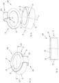
- a first embodiment of a closing device 10, hereinafter simply referred to also as a cap and carried out according to the present invention, is described below with reference to Figures from 1 to 7; in the figures, similar or equivalent characteristics and/or component parts are identified by the same reference numbers.
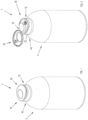
- Figure 1 shows the closing device 10 according to the embodiment of the present invention applied to a container 4 to form an assembly 1.
- the closing device 10 is in its closed configuration, that is, closed.
- Figure 2 shows the same closing device 10 applied to the container 4 in its open configuration.
- the container 4 shown in the figures is a substantially cylindrical container for containing, for example, a body wash.
- the container 4 is preferably made of a plastic material.
- Plastics usable for this purpose preferably consist of polypropylene (PP), polyethylene (PELLD, PELD, PEMD, PEHD), and other materials known as ABL, PBL, PCR, soft touch resin.
- the container may have another shape and/or be made of materials different from those indicated and/or described with reference to the preferred embodiments.
- the container may also be used for dispensing other types of products, for example preferably products in a fluid form, such as body care products like shampoos, toothpastes, or cosmetic products, such as cosmetic creams and the like.
- the container 4 has a head surface 4a, or neck portion at the upper end, where there is an opening, not visible in the figures, for filling and dispensing the product.
- the neck portion 4a preferably has a cylindrical shape.
- said neck portion 4a may have any other shape.
- the closing device 10 is advantageously applied to the container 4 through suitable connection means 20, for example by screwing, as is better described below.
- the cap may be associated with the container differently, for example through a snap connection or equivalent connection means.
- the neck portion 4a of the upper end of the container 4 is provided with respective connection means suited to enable the coupling of the cap 10 and not shown in the figures.
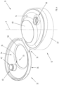
- the cap 10 clearly visible in Figures from 3 to 6, comprises a main body 12 and a lid 32 hinged to the main body 12.
- the main body 12 can be connected to the container 4, preferably to the neck portion 4a of the container 4 as indicated above.
- the main body 12 has an inner face 14, better visible in Figure 6 , and an outer face 16 opposite the inner face 14.
- the inner face 14 is suited to be arranged towards the container 4 when the cap 10 is connected to the container 4.
- the main body 12 preferably comprises also a through opening 18 between the outer face 16 and the inner face 14 for the passage of the product coming from the container 4.
- the main body 12 is also preferably provided with connection means 20 for connection to the container, more preferably with connection means for connection to the neck portion 4a of the container 4.
- connection means 20 are preferably defined by a neck portion 22 of the main body 12 extending towards the container 4 from its inner face 14.
- the neck portion 22 has a cylindrical shape.
- said neck portion 22 may have different shapes.
- connection means 20 preferably allow the cap 10 to be connected to the container 4 by screwing.
- the connection means 20 preferably comprise a nut thread portion 21 made internally at the level of the neck portion 22.
- the neck portion 4a of the container 4 is advantageously provided with a corresponding threaded portion made on the neck portion 4a of the container 4.
- connection means may be of a different type, for example by providing for the creation of suitable undercut engagement areas in the neck portion of the cap and the container.
- the lid 32 it is hinged to the main body 12 at the level of a hinge area 33.
- the main body 12 and the lid 32 are made so that they are integral with each other.
- the main body 12 and the lid 32 are made so that they are integral with each other through a plastic material injection moulding process.
- Plastics usable for this purpose are preferably constituted by polypropylene (PP) and/or polyethylene (PELLD, PELD, PEMD, and PEHD).
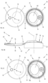
- the lid 32 can be moved, rotated in this case, in order to be arranged in a closed position, as for example shown in Figure 1 , 3 or 6 , and in at least one open position with respect to said main body 12, for example as shown in Figures 2 , 4 or 7 .
- the lid 32 preferably comprises an inner face 34 facing towards the main body 12 and an outer face 36 opposite the inner face 34.
- the inner face 34 faces towards the main body 12 when the lid 32 is in its closed position.
- the lid 32 preferably comprises closing means 40 suited to close the through opening 18 of the main body 12 when the main body 12 is in the closed position.
- the closing means 40 preferably comprise a reference element 42 suited to intercept the through opening 18 when the main body 12 is in the closed position and preferably to be inserted into the through opening 18.
- the lid 32 comprises a through opening 50 made between its outer face 36 and its inner face 34.
- the through opening 50 is shaped in such a way that in the closed position of the lid 32 with respect to the main body 12 at least one portion 60 of the outer face 16 of the main body 12 is visible.
- said creation of said through opening 50 makes it possible to reduce the use of raw material for the production of the lid 32, and therefore of the cap 10, with the consequent reduction of its weight and/or production costs.
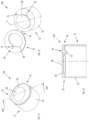
- said at least one portion 60 of the outer face 16 of the main body 12 is defined by an area that protrudes from the same outer face 16 of the main body 12, as visible in Figures 4 , 5B and 6 .
- Said protruding area 60 is preferably suited to be inserted into the through opening 50 of the lid 32 when the lid 32 is in the closed position with respect to the main body 12, as shown in Figure 3 and in the sectional view of Figure 6 .
- the protruding area 60 of the main body 12 and the through opening 50 of the lid 32 have a matching shape, in such a way that the shape of the protruding area 60 coincides, or substantially coincides, with the shape of the through opening 50 of the lid 12.
- the shape of the protruding area 60 is substantially elliptical.
- said shape may be different.
- the desired stability of the lid 32 in its closed position over the main body 12 is obtained and/or maintained.
- said at least one portion 60 of the outer face 16 of the main body 12 and the outer face 36 of the lid 32 are shaped in such a way as to form a continuous or substantially continuous surface. This can be appreciated in particular in Figure 6 , where it can be seen that passing from the outer face 36 of the lid 32 to the outer face 16 of the main body 12 defined by the protruding area 60 the surface is level or, in other words, there is no unevenness.
- the creation of said continuous, or substantially continuous, surface firstly provides a unique characteristic of continuity and overall aesthetic uniformity to the cap.
- the lack of different levels on the surface minimizes possible areas where dust/dirt could accumulate on the cap.
- the thickness SP of the main body 12 defined between its inner face 14 and outer face 16 remains constant, or substantially constant, throughout its length, in particular also at the level of the protruding area 60, as shown in Figure 6 .
- the protruding area 60 does not constitute an area of added material of the main body 12 but rather a "displacement" of material that allows the thickness of said main body 12 to be kept constant.
- the total thickness ST of the cap 10 intended as the thickness between the inner face 14 of the main body 12 and the outer face 36 of the lid 32 preferably has a first thickness ST1 while the total thickness ST2 of the cap 10 at the level of the through opening 50 is the same thickness SP as that of the protruding area 60.
- the total thickness ST2 of the cap 10 at the level of the through opening 50 is therefore smaller than the total thickness ST1 of the cap 10 outside the through opening 50.
- the thickness and therefore the material and/or weight of the cap according to the new solution is reduced compared to the total thickness of the caps of the known type, which is substantially constant throughout the length of the main body and the lid (given that the thickness is constituted everywhere by the sum of the thicknesses of the main body and the lid since it has no through opening).
- the lid 32 and the main body 12 are integral with each other, in such a way that the hinge area 33 and the through opening 18 of the main body 12 are positioned on opposite sides with respect to a central axis X passing through the cap 10. Accordingly, preferably, the hinge area 33 and the reference element 42 are also positioned on opposite sides with respect to the central axis X passing through the cap 10.
- the point of application of the opening force at the level of the gripping area 64 is close to the resistant area constituted by the reference element 42 inserted in the through opening 18 by interference.
- At least the main body 12 is made of a transparent material. In this way, it is possible to see the inside of the container 4 through the through opening 50 of the lid 32 and the transparent portion 60, or protruding area 60, of the main body 12.
- the through opening 50 of the lid 32 and the transparent portion 60 define a sort of porthole that allows the contents of the container 4 to be inspected to evaluate, for example, the residual amount of product.
- not all of the main body 12 is transparent but only its portion 60, or protruding area 60, in any case preferably and advantageously obtaining said porthole effect.
- the main body 12 and the lid 32 are made in different colours.
- the through opening 50 of the lid 32 is shaped to substantially define an eyelet in which at least one coupling area 70 is identified which is suited to enable the coupling of the cap 10, in its open position, with a coupling element G, or hook G (see Figure 7 ).
- the assembly 1 consisting of the container 4 and the cap 10 can be conveniently hung on the hook G simply by opening the lid 32.
- This operation can, for example, be particularly useful during the use of the assembly 1 when repeated dispensing of the product contained in it is expected or to facilitate the temporary positioning of the assembly 1 before it is definitively closed, for example during a shower in which the product of the assembly 1 consists of a body wash or a shampoo and the assembly can be hung on a special hook G present in the shower. The handling of the assembly 1 during its use is therefore facilitated.
- the coupling area 70 consists of at least one intermediate surface 35 joining the outer face 36 and the inner face 34 of the through opening 50 of the lid 32, as shown in Figure 4 .
- the main body 12 comprises at least one through opening 15a, 15b, in addition to the through opening 18 intended for the passage of the product coming from the container 4, made between the outer face 16 and the inner face 14 of the main body 12, as shown in the variant embodiment of Figure 5C .
- the amount of material used for producing the main body 12, and therefore the material used for producing the cap 910 is reduced compared to the caps known in the art.
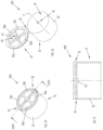
- Figures from 8 to 10 show a first variant embodiment of the cap 110 of the invention.
- the first variant embodiment differs from the embodiment described with reference to Figures from 1 to 7 mainly due to the different shape and size of the through opening 50 of the lid 32 and of the corresponding protruding area 60 of the main body 12, which are substantially circular instead of elliptical.
- Figures from 14 to 16 show a third variant embodiment of the cap 310 of the invention.
- Said variant embodiment differs from the embodiment described with reference to Figures from 1 to 7 due to the different shape and size of the through opening 50 of the lid 32 and of the corresponding protruding area 60 of the main body 12 as well as due to the different shape of the neck portion 22 of the main body 12, which has an elliptical rather than a cylindrical shape.
- Figures from 17 to 19 show a fourth variant embodiment of the cap 410 of the invention.
- Said variant embodiment differs from the embodiment described with reference to Figures from 1 to 7 due to the different shape and size of the through opening 50 of the lid 32 and of the corresponding protruding area 60 of the main body 12, which are substantially rectangular/square, as well as due to the different shape of the neck portion 22, which also has a square/rectangular shape.
- Figures from 20 to 22 show a fifth variant embodiment of the cap 510 of the invention.
- Said variant embodiment differs from the embodiment described with reference to Figures from 1 to 7 due to the different shape and size of the through opening 50 of the lid 32 and of the corresponding protruding area 60 of the main body 12, due to the different shape of the neck portion 22, which has an elliptical shape, as well as due to the fact that the lid 32 has a reduced size with respect to the underlying main body 12 in such a way that, in the closed position, lateral portions 16a, 16b of the outer surface 16 of the main body 12 remain visible.
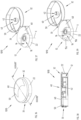
- Figures from 23 to 25 show a sixth variant embodiment of the cap 610 of the invention.
- Said variant embodiment shows a further characteristic of the present invention, which is that the lid 32 is equipped with coupling means 650 to provide a further area suitable for coupling the cap 610, and the assembly comprising the container, with a possible hook G.
- the coupling means 650 preferably comprise a curved surface portion 652 that extends peripherally from the lid 32.
- the embodiment of the cap 610 illustrated in Figures from 23 to 25 substantially corresponds to the cap 310 shown in Figures from 14 to 16, provided with said coupling means 650. It should be noted that any of the embodiments according to the present invention may be equipped with said further coupling means 650. Furthermore, in variant embodiments, the coupling means, which in this embodiment are constituted by the curved surface 652, may have any other shape suitable for the purpose.
- Figures from 26 to 28 show a seventh variant embodiment of the cap 710 of the invention.
- Said variant embodiment differs from the embodiment described with reference to Figures from 1 to 7 due to the different shape and size of the through opening 50 of the lid 32 as well as due to the fact that the upper face 16 of the main body 12 is flat, that is, without any protruding area.
- Figures from 29 to 31 show an eighth variant embodiment of the cap 810 of the invention.
- Said variant embodiment differs from the embodiment described with reference to Figures from 1 to 7 due to the fact that the upper face 16 of the main body 12 is flat, that is, without any protruding area, as well as due to the fact that the lid 32 has 4 openings 50a-50d, each substantially in the shape of a sector, and due to the fact that the through opening 18 of the main body 12 and the reference element 42 of the lid 32 are positioned centrally and preferably along the central axis X of the cap 810.
- Figures from 32 to 35 show a ninth variant embodiment of the cap 910 of the invention.
- Said variant embodiment differs from the embodiment described with reference to Figures from 1 to 7 mainly due to the fact that the size of the main body 12 is smaller than the size of the lid 32.
- the amount of material used for producing the main body 12, and therefore the material used for producing the cap 910 is reduced compared to the caps known in the art.
- the lid 32 In the closed position, the lid 32 is superimposed to the main body 12, completely covering it, and the lid 32 extends beyond the extension of the underlying main body 12.
- Figures from 36 to 38 show a tenth variant embodiment of the cap 1010 of the invention.
- Said variant embodiment differs from the embodiment described with reference to Figures from 32 to 35 first of all due to the different shape and size of the through opening 50 of the lid 32 and of the corresponding protruding area 60 of the main body 12 (an annulus sector instead of an elliptical shape).
- the size of the main body 12 is still smaller than the size of the lid 32.
- the difference in size between the lid 32 and the main body 12 is smaller.
- Figure 39 shows a variant embodiment of the cap 1010 of the invention described with reference to Figures from 36 to 38, in which the main body 12 comprises at least one through opening 15a, 15b, in addition to the through opening 18 intended for the passage of the product coming from the container 4, made between the outer face 16 and the inner face 14 of the main body 12.
- the closing device that is the subject of the invention makes it possible to achieve the established objects, and in particular makes it possible to reduce the amount of material needed for its production as well as its weight and/or production costs compared to the devices known in the art.
Landscapes
- Engineering & Computer Science (AREA)
- Mechanical Engineering (AREA)
- Closures For Containers (AREA)
- Cartons (AREA)
Claims (16)
- Dispositif de fermeture (10 ; 110 ; 210 ; 310 ; 410 ; 510 ; 610 ; 710 ; 810 ; 910 ; 1010) pour un récipient (4), comprenant ;- un corps principal (12) apte à être relié audit récipient (4), ledit corps principal (12) comportant une face intérieure (14) adaptée pour être disposée vers ledit récipient (4) lorsque ledit dispositif (10 ; 110 ; 210 ; 310 ; 410 ; 510 ; 610 ; 710 ; 810 ; 910 ; 1010) est relié audit récipient (4) et une face extérieure (16) opposée à ladite face intérieure (14), ledit corps principal (12) comprenant une ouverture traversante (18) créée entre ladite face extérieure (16) et ladite face intérieure (14) pour le passage d'un produit provenant dudit récipient (4) ;- un couvercle (32) articulé sur ledit corps principal (12) au niveau d'une zone de charnière (33), ledit couvercle (32) étant apte à être disposé dans une position fermée et dans au moins une position ouverte par rapport audit corps principal (12), ledit couvercle (32) présentant une face intérieure (34) orientée vers ledit corps principal (12), dans ladite position fermée, et une face extérieure (36) opposée à ladite face intérieure (34), ledit couvercle (32) comprenant des moyens de fermeture (40) aptes à fermer ladite ouverture traversante (18) dudit corps principal (12) dans ladite position fermée, ledit corps principal (12) et ledit couvercle (32) étant réalisés de manière à être solidaires l'un de l'autre ;caractérisé en ce qu'il comprend une ouverture traversante (50) créée entre ladite face extérieure (36) et ladite face intérieure (34) dudit couvercle (32) de telle sorte que dans ladite position fermée dudit couvercle (32) par rapport audit corps principal (12), au moins une partie (60) de ladite face extérieure (16) dudit corps principal (12) est visible.
- Dispositif (10 ; 110 ; 210 ; 310 ; 410 ; 510 ; 610 ; 910 ; 1010) selon la revendication 1, caractérisé en ce que ladite au moins une partie (60) de ladite face extérieure (16) dudit corps principal (12) et ladite face extérieure (36) dudit couvercle (32) sont façonnées de manière à former une surface continue ou sensiblement continue.
- Dispositif (10 ; 110 ; 210 ; 310 ; 410 ; 510 ; 610 ; 910 ; 1010) selon la revendication 1 ou 2, caractérisé en ce que ladite au moins une partie (60) de ladite face extérieure (16) dudit corps principal (12) est définie par une zone saillante (60) qui fait saillie de ladite face extérieure (16) dudit corps principal (12), ladite zone saillante (60) étant apte à être insérée dans ladite ouverture traversante (50) dudit couvercle (32) lorsque ledit couvercle (32) est dans ladite position fermée par rapport audit corps principal (12).
- Dispositif (10 ; 110 ; 210 ; 310 ; 410 ; 510 ; 610 ; 910 ; 1010) selon la revendication 3, caractérisé en ce que ladite zone saillante (60) qui dépasse de ladite face extérieure (16) dudit corps principal (12) et ladite face extérieure (36) dudit capuchon (32) sont façonnées de manière à former une surface continue ou sensiblement continue.
- Dispositif (10 ; 110 ; 210 ; 310 ; 410 ; 510 ; 610 ; 710 ; 810 ; 910 ; 1010) selon l'une quelconque des revendications précédentes, caractérisé en ce que l'épaisseur (SP) dudit corps principal (12) définie entre ladite face intérieure (14) et ladite face extérieure (16) est constante ou sensiblement constante.
- Dispositif (10 ; 110 ; 210 ; 310 ; 410 ; 510 ; 610 ; 910 ; 1010) selon la revendication 4 ou 5, caractérisé en ce que ladite zone saillante (60) dudit corps principal (12) et ladite ouverture traversante (50) dudit capuchon (32) ont une forme correspondante, de sorte que la forme de ladite zone saillante (60) coïncide avec la forme de ladite ouverture traversante (50) dudit capuchon (32).
- Dispositif (10 ; 110 ; 210 ; 310 ; 410 ; 510 ; 610 ; 710 ; 810 ; 910 ; 1010) selon l'une quelconque des revendications précédentes, caractérisé en ce que ladite zone de charnière (33) et ladite ouverture traversante (18) dudit corps principal (12) sont positionnées sur des côtés opposés par rapport à un axe central (X) traversant ledit dispositif (10 ; 110 ; 210 ; 310 ; 410 ; 510 ; 610 ; 710 ; 810 ; 910 ; 1010).
- Dispositif (10 ; 110 ; 210 ; 310 ; 410 ; 510 ; 610 ; 710 ; 810 ; 910 ; 1010) selon l'une quelconque des revendications précédentes, caractérisé en ce que ledit corps principal (12) est constitué d'un matériau transparent.
- Dispositif (10 ; 110 ; 210 ; 310 ; 410 ; 510 ; 610 ; 710 ; 810 ; 910 ; 1010) selon l'une quelconque des revendications précédentes, caractérisé en ce que ladite au moins une partie (60) de ladite face extérieure dudit corps principal (12) est constituée d'un matériau transparent.
- Dispositif (10 ; 110 ; 210 ; 310 ; 410 ; 510 ; 610 ; 710 ; 810 ; 910 ; 1010) selon l'une quelconque des revendications précédentes, caractérisé en ce que ledit corps principal (12) et ledit capuchon (32) sont réalisés dans des couleurs respectivement différentes.
- Dispositif (10 ; 110 ; 210 ; 310 ; 410 ; 510 ; 610 ; 710 ; 810 ; 910 ; 1010) selon l'une quelconque des revendications précédentes, caractérisé en ce que lesdits moyens de fermeture (40) comprennent un élément de référence (42) apte à intercepter ladite ouverture traversante (18) dudit corps principal (12).
- Dispositif (10 ; 110 ; 210 ; 310 ; 410 ; 510 ; 610 ; 710 ; 810 ; 910 ; 1010) selon l'une quelconque des revendications précédentes, caractérisé en ce que ladite ouverture traversante (50) dudit capuchon (32) est façonnée de telle sorte que ledit capuchon (32), en position ouverte, définit un œillet apte à permettre l'accouplement dudit dispositif (10 ; 110 ; 210 ; 310 ; 410 ; 510 ; 610 ; 710 ; 810 ; 910 ; 1010) avec un élément d'accouplement (G).
- Dispositif (610) selon l'une quelconque des revendications précédentes, caractérisé en ce que ledit capuchon (32) comprend un moyen d'accouplement (650) apte à permettre l'accouplement dudit dispositif (610) avec un élément d'accouplement (G).
- Dispositif (10 ; 110 ; 210 ; 310 ; 410 ; 510 ; 610 ; 710 ; 810 ; 910 ; 1010) selon l'une quelconque des revendications précédentes, caractérisé en ce qu'il comprend un moyen de raccordement (20) pour le raccordement audit récipient (4).
- Ensemble (1 ; 1001) comprenant un récipient (4) et un dispositif de dosage (10 ; 110 ; 210 ; 310 ; 410 ; 510 ; 610 ; 710 ; 810 ; 910 ; 1010) associé audit récipient (4), caractérisé en ce que ledit dispositif de fermeture (10 ; 110 ; 210 ; 310 ; 410 ; 510 ; 610 ; 710 ; 810 ; 910 ; 1010) est un dispositif de fermeture (10 ; 110 ; 210 ; 310 ; 410 ; 510 ; 610 ; 710 ; 810 ; 910 ; 1010) selon l'une quelconque des revendications précédentes.
- Ensemble (1001) selon la revendication 15, caractérisé en ce qu'au moins une partie d'une surface (4b) dudit récipient (4) fait directement face à une partie correspondante (34a) de ladite face intérieure (34) dudit bouchon (32) sans l'interposition dudit corps principal (12) lorsque ledit dispositif de fermeture (910 ; 1010) est dans sa position fermée.
Applications Claiming Priority (2)
| Application Number | Priority Date | Filing Date | Title |
|---|---|---|---|
| IT102021000012413A IT202100012413A1 (it) | 2021-05-13 | 2021-05-13 | Dispositivo di chiusura per contenitori ed assieme comprendente un contenitore provvisto di tale dispositivo di chiusura |
| PCT/IB2022/054021 WO2022238809A1 (fr) | 2021-05-13 | 2022-05-02 | Dispositif de fermeture pour récipients et ensemble comprenant un récipient muni dudit dispositif de fermeture |
Publications (2)
| Publication Number | Publication Date |
|---|---|
| EP4337560A1 EP4337560A1 (fr) | 2024-03-20 |
| EP4337560B1 true EP4337560B1 (fr) | 2025-05-28 |
Family
ID=77317252
Family Applications (1)
| Application Number | Title | Priority Date | Filing Date |
|---|---|---|---|
| EP22721899.7A Active EP4337560B1 (fr) | 2021-05-13 | 2022-05-02 | Dispositif de fermeture pour récipients et ensemble comprenant un récipient muni dudit dispositif de fermeture |
Country Status (9)
| Country | Link |
|---|---|
| US (1) | US12589922B2 (fr) |
| EP (1) | EP4337560B1 (fr) |
| CN (1) | CN117295666A (fr) |
| BR (1) | BR112023022710A2 (fr) |
| ES (1) | ES3040789T3 (fr) |
| IT (1) | IT202100012413A1 (fr) |
| MX (1) | MX2023013356A (fr) |
| PL (1) | PL4337560T3 (fr) |
| WO (1) | WO2022238809A1 (fr) |
Family Cites Families (9)
| Publication number | Priority date | Publication date | Assignee | Title |
|---|---|---|---|---|
| US4127221A (en) * | 1978-03-20 | 1978-11-28 | Sterling Drug Inc. | Childproof device for containing and dispensing fluids |
| US5356017A (en) * | 1992-10-28 | 1994-10-18 | Aptargroup, Inc. | Child resistant closure with recessed latch |
| US5547109A (en) * | 1992-11-19 | 1996-08-20 | Robbins, Iii; Edward S. | Container and measuring/dispensing cap assembly |
| DE29713186U1 (de) * | 1997-07-24 | 1998-12-03 | ALPLA-Design Lehner GmbH, 96515 Sonneberg | Kunststoffkappe mit Aufhängeteil für ein Flaschenbehältnis |
| AU2003273709B2 (en) * | 2002-11-11 | 2009-10-08 | Sig Technology Ltd. | Tamper-proof hinged closure for film-sealed bottles and containers filled with pourable contents |
| US8006853B2 (en) * | 2005-05-09 | 2011-08-30 | L'oreal | Closure cap and a receptacle fitted therewith |
| US20090236339A1 (en) * | 2008-03-20 | 2009-09-24 | Seaquist Closures L.L.C. | Dispensing closure with orifice external seal |
| ITVI20110294A1 (it) * | 2011-11-04 | 2013-05-05 | Giflor S R L | Elemento di chiusura per contenitori. |
| CA2955029C (fr) * | 2014-07-30 | 2022-11-08 | Nestec S.A. | Appareils et procedes pour enfermer un fourrage dans un produit alimentaire |
-
2021
- 2021-05-13 IT IT102021000012413A patent/IT202100012413A1/it unknown
-
2022
- 2022-05-02 BR BR112023022710A patent/BR112023022710A2/pt unknown
- 2022-05-02 MX MX2023013356A patent/MX2023013356A/es unknown
- 2022-05-02 US US18/289,134 patent/US12589922B2/en active Active
- 2022-05-02 PL PL22721899.7T patent/PL4337560T3/pl unknown
- 2022-05-02 ES ES22721899T patent/ES3040789T3/es active Active
- 2022-05-02 EP EP22721899.7A patent/EP4337560B1/fr active Active
- 2022-05-02 WO PCT/IB2022/054021 patent/WO2022238809A1/fr not_active Ceased
- 2022-05-02 CN CN202280034266.0A patent/CN117295666A/zh active Pending
Also Published As
| Publication number | Publication date |
|---|---|
| US12589922B2 (en) | 2026-03-31 |
| IT202100012413A1 (it) | 2022-11-13 |
| CN117295666A (zh) | 2023-12-26 |
| US20240228131A1 (en) | 2024-07-11 |
| BR112023022710A2 (pt) | 2024-01-16 |
| ES3040789T3 (en) | 2025-11-05 |
| EP4337560A1 (fr) | 2024-03-20 |
| PL4337560T3 (pl) | 2025-09-15 |
| WO2022238809A1 (fr) | 2022-11-17 |
| MX2023013356A (es) | 2023-11-27 |
Similar Documents
| Publication | Publication Date | Title |
|---|---|---|
| CN101646609B (zh) | 具有低轮廓帽的容器 | |
| US7857155B2 (en) | Closure for high torque installation on a container | |
| US5642824A (en) | Closure with multiple axis bistable hinge structure | |
| CA2456525C (fr) | Fermeture inviolable | |
| US4911324A (en) | Plastic snap hinge closure | |
| EP1496785B1 (fr) | Bouchon frotteur | |
| USRE38816E1 (en) | Dispensing cap with gripping means | |
| EP3630637B1 (fr) | Récipient | |
| AU2005290254B2 (en) | Multiple lid closure with open lid retention feature | |
| AU2007261725B2 (en) | Dispensing system with a dispensing valve having a projecting, reduced size discharge end | |
| US7299952B2 (en) | Container closure and method of assembly | |
| CN101238043A (zh) | 关闭件 | |
| US20040069677A1 (en) | Container with removable protective element | |
| AU2002320516A1 (en) | Tamper-evident closure | |
| US6260722B1 (en) | Cap and container assembly | |
| EP2250102A1 (fr) | Fermeture pourvue d une articulation externe | |
| AU2006333344A1 (en) | Closure with hinged lid and stress relief recesses | |
| EP4188821B1 (fr) | Bouchon de contenant se fixant par encliquetage et s'enlevant par torsion | |
| US6257432B1 (en) | Cap and container assembly | |
| EP4337560B1 (fr) | Dispositif de fermeture pour récipients et ensemble comprenant un récipient muni dudit dispositif de fermeture | |
| US6578744B2 (en) | Watertight tube closure | |
| US6143229A (en) | Method for making a dispensing closure with a finger well formed after molding of the dispensing closure | |
| US20240375837A1 (en) | Container closure | |
| JP2004083136A (ja) | 特に最初に使用する前に取り外し可能である保護要素を有する容器 | |
| EP2773570B1 (fr) | Ensemble comprennant un conteneus et un élément de fermeture |
Legal Events
| Date | Code | Title | Description |
|---|---|---|---|
| STAA | Information on the status of an ep patent application or granted ep patent |
Free format text: STATUS: UNKNOWN |
|
| STAA | Information on the status of an ep patent application or granted ep patent |
Free format text: STATUS: THE INTERNATIONAL PUBLICATION HAS BEEN MADE |
|
| PUAI | Public reference made under article 153(3) epc to a published international application that has entered the european phase |
Free format text: ORIGINAL CODE: 0009012 |
|
| STAA | Information on the status of an ep patent application or granted ep patent |
Free format text: STATUS: REQUEST FOR EXAMINATION WAS MADE |
|
| 17P | Request for examination filed |
Effective date: 20231107 |
|
| AK | Designated contracting states |
Kind code of ref document: A1 Designated state(s): AL AT BE BG CH CY CZ DE DK EE ES FI FR GB GR HR HU IE IS IT LI LT LU LV MC MK MT NL NO PL PT RO RS SE SI SK SM TR |
|
| P01 | Opt-out of the competence of the unified patent court (upc) registered |
Effective date: 20240424 |
|
| DAX | Request for extension of the european patent (deleted) | ||
| RAV | Requested validation state of the european patent: fee paid |
Extension state: TN Effective date: 20231107 Extension state: MA Effective date: 20231107 |
|
| GRAP | Despatch of communication of intention to grant a patent |
Free format text: ORIGINAL CODE: EPIDOSNIGR1 |
|
| STAA | Information on the status of an ep patent application or granted ep patent |
Free format text: STATUS: GRANT OF PATENT IS INTENDED |
|
| INTG | Intention to grant announced |
Effective date: 20241217 |
|
| GRAS | Grant fee paid |
Free format text: ORIGINAL CODE: EPIDOSNIGR3 |
|
| GRAA | (expected) grant |
Free format text: ORIGINAL CODE: 0009210 |
|
| STAA | Information on the status of an ep patent application or granted ep patent |
Free format text: STATUS: THE PATENT HAS BEEN GRANTED |
|
| AK | Designated contracting states |
Kind code of ref document: B1 Designated state(s): AL AT BE BG CH CY CZ DE DK EE ES FI FR GB GR HR HU IE IS IT LI LT LU LV MC MK MT NL NO PL PT RO RS SE SI SK SM TR |
|
| REG | Reference to a national code |
Ref country code: GB Ref legal event code: FG4D |
|
| REG | Reference to a national code |
Ref country code: CH Ref legal event code: EP |
|
| REG | Reference to a national code |
Ref country code: IE Ref legal event code: FG4D Ref country code: DE Ref legal event code: R096 Ref document number: 602022015212 Country of ref document: DE |
|
| REG | Reference to a national code |
Ref country code: NL Ref legal event code: MP Effective date: 20250528 |
|
| PG25 | Lapsed in a contracting state [announced via postgrant information from national office to epo] |
Ref country code: FI Free format text: LAPSE BECAUSE OF FAILURE TO SUBMIT A TRANSLATION OF THE DESCRIPTION OR TO PAY THE FEE WITHIN THE PRESCRIBED TIME-LIMIT Effective date: 20250528 |
|
| REG | Reference to a national code |
Ref country code: LT Ref legal event code: MG9D |
|
| PG25 | Lapsed in a contracting state [announced via postgrant information from national office to epo] |
Ref country code: GR Free format text: LAPSE BECAUSE OF FAILURE TO SUBMIT A TRANSLATION OF THE DESCRIPTION OR TO PAY THE FEE WITHIN THE PRESCRIBED TIME-LIMIT Effective date: 20250829 Ref country code: NO Free format text: LAPSE BECAUSE OF FAILURE TO SUBMIT A TRANSLATION OF THE DESCRIPTION OR TO PAY THE FEE WITHIN THE PRESCRIBED TIME-LIMIT Effective date: 20250828 |
|
| PG25 | Lapsed in a contracting state [announced via postgrant information from national office to epo] |
Ref country code: NL Free format text: LAPSE BECAUSE OF FAILURE TO SUBMIT A TRANSLATION OF THE DESCRIPTION OR TO PAY THE FEE WITHIN THE PRESCRIBED TIME-LIMIT Effective date: 20250528 |
|
| PG25 | Lapsed in a contracting state [announced via postgrant information from national office to epo] |
Ref country code: BG Free format text: LAPSE BECAUSE OF FAILURE TO SUBMIT A TRANSLATION OF THE DESCRIPTION OR TO PAY THE FEE WITHIN THE PRESCRIBED TIME-LIMIT Effective date: 20250528 |
|
| PG25 | Lapsed in a contracting state [announced via postgrant information from national office to epo] |
Ref country code: HR Free format text: LAPSE BECAUSE OF FAILURE TO SUBMIT A TRANSLATION OF THE DESCRIPTION OR TO PAY THE FEE WITHIN THE PRESCRIBED TIME-LIMIT Effective date: 20250528 |
|
| PG25 | Lapsed in a contracting state [announced via postgrant information from national office to epo] |
Ref country code: RS Free format text: LAPSE BECAUSE OF FAILURE TO SUBMIT A TRANSLATION OF THE DESCRIPTION OR TO PAY THE FEE WITHIN THE PRESCRIBED TIME-LIMIT Effective date: 20250828 |
|
| PG25 | Lapsed in a contracting state [announced via postgrant information from national office to epo] |
Ref country code: IS Free format text: LAPSE BECAUSE OF FAILURE TO SUBMIT A TRANSLATION OF THE DESCRIPTION OR TO PAY THE FEE WITHIN THE PRESCRIBED TIME-LIMIT Effective date: 20250928 |
|
| PG25 | Lapsed in a contracting state [announced via postgrant information from national office to epo] |
Ref country code: LV Free format text: LAPSE BECAUSE OF FAILURE TO SUBMIT A TRANSLATION OF THE DESCRIPTION OR TO PAY THE FEE WITHIN THE PRESCRIBED TIME-LIMIT Effective date: 20250528 |
|
| REG | Reference to a national code |
Ref country code: ES Ref legal event code: FG2A Ref document number: 3040789 Country of ref document: ES Kind code of ref document: T3 Effective date: 20251105 |
|
| PG25 | Lapsed in a contracting state [announced via postgrant information from national office to epo] |
Ref country code: SM Free format text: LAPSE BECAUSE OF FAILURE TO SUBMIT A TRANSLATION OF THE DESCRIPTION OR TO PAY THE FEE WITHIN THE PRESCRIBED TIME-LIMIT Effective date: 20250528 Ref country code: DK Free format text: LAPSE BECAUSE OF FAILURE TO SUBMIT A TRANSLATION OF THE DESCRIPTION OR TO PAY THE FEE WITHIN THE PRESCRIBED TIME-LIMIT Effective date: 20250528 |
|
| PG25 | Lapsed in a contracting state [announced via postgrant information from national office to epo] |
Ref country code: CZ Free format text: LAPSE BECAUSE OF FAILURE TO SUBMIT A TRANSLATION OF THE DESCRIPTION OR TO PAY THE FEE WITHIN THE PRESCRIBED TIME-LIMIT Effective date: 20250528 |
|
| PG25 | Lapsed in a contracting state [announced via postgrant information from national office to epo] |
Ref country code: EE Free format text: LAPSE BECAUSE OF FAILURE TO SUBMIT A TRANSLATION OF THE DESCRIPTION OR TO PAY THE FEE WITHIN THE PRESCRIBED TIME-LIMIT Effective date: 20250528 |
|
| PG25 | Lapsed in a contracting state [announced via postgrant information from national office to epo] |
Ref country code: SK Free format text: LAPSE BECAUSE OF FAILURE TO SUBMIT A TRANSLATION OF THE DESCRIPTION OR TO PAY THE FEE WITHIN THE PRESCRIBED TIME-LIMIT Effective date: 20250528 |
|
| REG | Reference to a national code |
Ref country code: DE Ref legal event code: R097 Ref document number: 602022015212 Country of ref document: DE |
|
| PLBE | No opposition filed within time limit |
Free format text: ORIGINAL CODE: 0009261 |
|
| STAA | Information on the status of an ep patent application or granted ep patent |
Free format text: STATUS: NO OPPOSITION FILED WITHIN TIME LIMIT |
|
| REG | Reference to a national code |
Ref country code: CH Ref legal event code: L10 Free format text: ST27 STATUS EVENT CODE: U-0-0-L10-L00 (AS PROVIDED BY THE NATIONAL OFFICE) Effective date: 20260409 |
|
| VS25 | Lapsed in a validation state [announced via postgrant information from nat. office to epo] |
Ref country code: MA Free format text: LAPSE BECAUSE OF FAILURE TO SUBMIT A TRANSLATION OF THE DESCRIPTION OR TO PAY THE FEE WITHIN THE PRESCRIBED TIME-LIMIT Effective date: 20250528 |