EP4337592B1 - Système de transport mobile - Google Patents
Système de transport mobile Download PDFInfo
- Publication number
- EP4337592B1 EP4337592B1 EP22725996.7A EP22725996A EP4337592B1 EP 4337592 B1 EP4337592 B1 EP 4337592B1 EP 22725996 A EP22725996 A EP 22725996A EP 4337592 B1 EP4337592 B1 EP 4337592B1
- Authority
- EP
- European Patent Office
- Prior art keywords
- lifting
- transport system
- mobile transport
- lifting devices
- case
- Prior art date
- Legal status (The legal status is an assumption and is not a legal conclusion. Google has not performed a legal analysis and makes no representation as to the accuracy of the status listed.)
- Active
Links
Images




Classifications
-
- B—PERFORMING OPERATIONS; TRANSPORTING
- B65—CONVEYING; PACKING; STORING; HANDLING THIN OR FILAMENTARY MATERIAL
- B65G—TRANSPORT OR STORAGE DEVICES, e.g. CONVEYORS FOR LOADING OR TIPPING, SHOP CONVEYOR SYSTEMS OR PNEUMATIC TUBE CONVEYORS
- B65G1/00—Storing articles, individually or in orderly arrangement, in warehouses or magazines
- B65G1/02—Storage devices
- B65G1/04—Storage devices mechanical
- B65G1/0492—Storage devices mechanical with cars adapted to travel in storage aisles
-
- B—PERFORMING OPERATIONS; TRANSPORTING
- B66—HOISTING; LIFTING; HAULING
- B66F—HOISTING, LIFTING, HAULING OR PUSHING, NOT OTHERWISE PROVIDED FOR, e.g. DEVICES WHICH APPLY A LIFTING OR PUSHING FORCE DIRECTLY TO THE SURFACE OF A LOAD
- B66F9/00—Devices for lifting or lowering bulky or heavy goods for loading or unloading purposes
- B66F9/06—Devices for lifting or lowering bulky or heavy goods for loading or unloading purposes movable, with their loads, on wheels or the like, e.g. fork-lift trucks
- B66F9/063—Automatically guided
-
- B—PERFORMING OPERATIONS; TRANSPORTING
- B62—LAND VEHICLES FOR TRAVELLING OTHERWISE THAN ON RAILS
- B62D—MOTOR VEHICLES; TRAILERS
- B62D65/00—Designing, manufacturing, e.g. assembling, facilitating disassembly, or structurally modifying motor vehicles or trailers, not otherwise provided for
- B62D65/02—Joining sub-units or components to, or positioning sub-units or components with respect to, body shell or other sub-units or components
- B62D65/18—Transportation, conveyor or haulage systems specially adapted for motor vehicle or trailer assembly lines
-
- B—PERFORMING OPERATIONS; TRANSPORTING
- B65—CONVEYING; PACKING; STORING; HANDLING THIN OR FILAMENTARY MATERIAL
- B65G—TRANSPORT OR STORAGE DEVICES, e.g. CONVEYORS FOR LOADING OR TIPPING, SHOP CONVEYOR SYSTEMS OR PNEUMATIC TUBE CONVEYORS
- B65G35/00—Mechanical conveyors not otherwise provided for
-
- B—PERFORMING OPERATIONS; TRANSPORTING
- B65—CONVEYING; PACKING; STORING; HANDLING THIN OR FILAMENTARY MATERIAL
- B65G—TRANSPORT OR STORAGE DEVICES, e.g. CONVEYORS FOR LOADING OR TIPPING, SHOP CONVEYOR SYSTEMS OR PNEUMATIC TUBE CONVEYORS
- B65G43/00—Control devices, e.g. for safety, warning or fault-correcting
-
- B—PERFORMING OPERATIONS; TRANSPORTING
- B66—HOISTING; LIFTING; HAULING
- B66F—HOISTING, LIFTING, HAULING OR PUSHING, NOT OTHERWISE PROVIDED FOR, e.g. DEVICES WHICH APPLY A LIFTING OR PUSHING FORCE DIRECTLY TO THE SURFACE OF A LOAD
- B66F7/00—Lifting frames, e.g. for lifting vehicles; Platform lifts
- B66F7/10—Lifting frames, e.g. for lifting vehicles; Platform lifts with platforms supported directly by jacks
- B66F7/12—Lifting frames, e.g. for lifting vehicles; Platform lifts with platforms supported directly by jacks by mechanical jacks
- B66F7/14—Lifting frames, e.g. for lifting vehicles; Platform lifts with platforms supported directly by jacks by mechanical jacks screw operated
-
- B—PERFORMING OPERATIONS; TRANSPORTING
- B66—HOISTING; LIFTING; HAULING
- B66F—HOISTING, LIFTING, HAULING OR PUSHING, NOT OTHERWISE PROVIDED FOR, e.g. DEVICES WHICH APPLY A LIFTING OR PUSHING FORCE DIRECTLY TO THE SURFACE OF A LOAD
- B66F9/00—Devices for lifting or lowering bulky or heavy goods for loading or unloading purposes
- B66F9/06—Devices for lifting or lowering bulky or heavy goods for loading or unloading purposes movable, with their loads, on wheels or the like, e.g. fork-lift trucks
- B66F9/075—Constructional features or details
- B66F9/07513—Details concerning the chassis
-
- B—PERFORMING OPERATIONS; TRANSPORTING
- B66—HOISTING; LIFTING; HAULING
- B66F—HOISTING, LIFTING, HAULING OR PUSHING, NOT OTHERWISE PROVIDED FOR, e.g. DEVICES WHICH APPLY A LIFTING OR PUSHING FORCE DIRECTLY TO THE SURFACE OF A LOAD
- B66F9/00—Devices for lifting or lowering bulky or heavy goods for loading or unloading purposes
- B66F9/06—Devices for lifting or lowering bulky or heavy goods for loading or unloading purposes movable, with their loads, on wheels or the like, e.g. fork-lift trucks
- B66F9/075—Constructional features or details
- B66F9/0755—Position control; Position detectors
-
- B—PERFORMING OPERATIONS; TRANSPORTING
- B66—HOISTING; LIFTING; HAULING
- B66F—HOISTING, LIFTING, HAULING OR PUSHING, NOT OTHERWISE PROVIDED FOR, e.g. DEVICES WHICH APPLY A LIFTING OR PUSHING FORCE DIRECTLY TO THE SURFACE OF A LOAD
- B66F9/00—Devices for lifting or lowering bulky or heavy goods for loading or unloading purposes
- B66F9/06—Devices for lifting or lowering bulky or heavy goods for loading or unloading purposes movable, with their loads, on wheels or the like, e.g. fork-lift trucks
- B66F9/075—Constructional features or details
- B66F9/07572—Propulsion arrangements
Definitions
- a transport robot which has a frame and a platform which is height-adjustable relative to the frame.
- the lifting unit comprises a lifting motor, a central gearbox, two lateral gearboxes, and a plurality of connecting shafts.
- the central gearbox transmits the rotation of an output shaft of the lifting motor via two connecting shafts to the two lateral gearboxes.
- the two lateral gearboxes each transmit said rotation via two connecting shafts to the lifting devices, in particular to the spindle nuts of the lifting devices.
- the lifting unit comprises two output shafts, each coupled to one of the lateral gears.
- the output shafts each extend through a designated opening in the center frame.
- the output shafts are thus accessible from outside the center frame.
- the output shafts can be driven, for example, using hand cranks or cordless screwdrivers, and the lifting unit can be operated manually.
- the lifting devices each comprise a housing in which the spindle nut is arranged.
- the housings of the lifting devices are each firmly connected to the center frame.
- the lifting motor, the central gear, and the lateral gears are each firmly connected to the center frame. This advantageously increases the strength of the lifting unit.
- the output shaft of the lifting motor rotates about an axis that runs at least approximately in the longitudinal direction and which drives the central gear.
- the lateral gears are each coupled to the central gear via a connecting shaft.
- Said connecting shafts each run in the transverse direction from the central gear to the lateral gears and are attached to opposite sides of the central gear.
- the lateral gears are each coupled to two of the lifting devices via two connecting shafts.
- Said connecting shafts each run in the longitudinal direction from the lateral gears to the lifting devices and are attached to opposite sides of the lateral gears.
- the mobile transport system has a receiving unit to which energy can be inductively transferred from a charging unit.
- the charging unit is designed, for example, as a linear conductor or a coil and is stationary in the floor.
- the energy inductively transferred from the charging unit to the receiving unit serves, for example, to charge an electrical energy storage device of the mobile transport system.
- Figure 1 shows a perspective view of a mobile transport system 10.
- the mobile transport system 10 is used in this case for transporting objects in a technical facility.
- the technical facility is an industrial application, for example, a production plant.
- the transport system 10 is also used, for example, for delivering goods to a private recipient's home in a city or residential area.
- the mobile transport system 10 is an autonomously driving vehicle.
- the mobile transport system 10 is located on a level floor.
- a longitudinal direction X corresponds at least approximately to the usual direction of travel of the mobile transport system 10.
- a transverse direction Y runs perpendicular to the longitudinal direction X.
- the longitudinal direction X and the transverse direction Y represent horizontal directions and run parallel to the floor on which the mobile transport system 10 is located.
- a vertical direction Z is perpendicular to the floor and thus runs perpendicular to the longitudinal direction X and perpendicular to the transverse direction Y. Every direction perpendicular to the vertical direction Z represents a horizontal direction.
- the mobile transport system 10 has a receiving unit 20, to which energy can be inductively transmitted from a charging unit.
- the charging unit is designed, for example, as a linear conductor or a coil.
- the energy inductively transmitted from the charging unit to the receiving unit 20 serves, for example, to charge an electrical energy storage device of the mobile transport system 10.
- the receiving unit 20 is located in a central area on a front side of the mobile transport system 10.
- the mobile transport system 10 further comprises a plurality of laser scanners 25.
- the laser scanners 25 are arranged in particular in a corner area of the front side and a long side, as well as in a corner area of a rear side and a long side.
- the laser scanners 25 serve to detect obstacles and to navigate the mobile transport system 10 within the technical system.
- FIG. 2 shows a perspective view of structural parts of the mobile transport system 10.
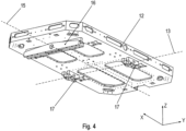
- the mobile transport system 10 comprises a lower frame 14, a middle frame 12 and an upper frame 18.
- the said frames 12, 14, 18 are relatively flat and extend predominantly in the longitudinal direction X and the transverse direction Y.
- the said frames 12, 14, 18 therefore each have only a relatively small extent in the vertical direction Z.
- the frames 12, 14, 18 are arranged one above the other in the vertical direction Z.
- the lower frame 14 is arranged facing the floor.
- the upper frame 18 is arranged facing away from the floor.
- the middle frame 12 is arranged in the vertical direction Z between the lower frame 14 and the upper frame 18.
- the said frames 12, 14, 18 are mechanically connected to one another, as explained in more detail below.
- the upper frame 18 is movably mounted relative to the middle frame 12.
- the lower frame 14 is also movably mounted relative to the middle frame 12.
- the lower frame 14, the middle frame 12, and the upper frame 18 are each made of metal.
- the frames 12, 14, and 18 each have a plurality of openings and apertures. These openings and apertures serve, in part, to secure components. The openings and apertures also improve air circulation within the mobile transport system 10 and thus improve heat dissipation.
- the individual frames 12, 14, and 18 are first prefabricated. The required components are then mounted on the individual frames 12, 14, and 18. The prefabricated frames 12, 14, and 18 are then connected to one another.
- FIG 3 shows a perspective view of a lifting unit 90 of the mobile transport system 10.
- the lifting unit 90 comprises several components which are connected to the central frame 12.
- the lifting unit 90 is arranged on a side of the central frame 12 facing the upper frame 18.
- the upper frame 18 (not shown here) is connected to the central frame 12 via the said lifting unit 90.
- the lifting unit 90 By means of the lifting unit 90, the upper frame 18 is movable relative to the central frame 12 in the vertical direction Z.
- the lifting unit 90 has several, in this case four, lifting devices 91.
- Each of the lifting devices 91 comprises a spindle and a spindle nut, which is rotatable relative to the spindle about a central axis.
- the spindles and spindle nuts of the lifting devices 91 are hidden in this illustration.
- the central axes of the spindles of the lifting devices 91 run parallel to one another in the vertical direction Z.
- the lifting devices 91 each comprise a housing in which the spindle nut is arranged.
- the said housings of the lifting devices 91 are each fixedly connected to the central frame 12.
- the central gear 93 is rigidly connected to the center frame 12.
- the lateral gears 94 are also rigidly connected to the center frame 12.
- the lateral gears 94 are each coupled to the central gear 93 via a connecting shaft 95.
- the said connecting shafts 95 are mounted on opposite sides of the central gear 93.
- the said connecting shafts 95 each extend in the transverse direction Y from the central gear 93 to the lateral gears 94.
- the central gear 93 transmits the rotation of the output shaft of the lifting motor 92 via the two connecting shafts 95, which run in the transverse direction Y, to the two lateral gears 94.
- the two lateral gears 94 each transmit said rotation via two connecting shafts 95, which run in the longitudinal direction X, to the lifting devices 91, in particular to the spindle nuts of the lifting devices 91.
- the lifting unit 90 further comprises two output shafts 96.
- the output shafts 96 are each coupled to one of the lateral gears 94.
- Said output shafts 96 are each mounted on the sides of the lateral gears 94, which are opposite the central gear 93.
- the output shafts 96 each extend in the transverse direction Y and each pass through an opening provided for this purpose in the center frame 12.
- the output shafts 96 are thus accessible outside the center frame 12 and can be driven, for example, by means of hand cranks or cordless screwdrivers.
- the spindle nuts of the lifting devices 91 are driven in rotation via the lateral gears 94 and the connecting shafts 95.
- the spindles thereby undergo a translational movement in the vertical direction Z. This also moves the mounting flanges and the upper frame 18 in the vertical direction Z.
Landscapes
- Engineering & Computer Science (AREA)
- Transportation (AREA)
- Structural Engineering (AREA)
- Mechanical Engineering (AREA)
- Life Sciences & Earth Sciences (AREA)
- Geology (AREA)
- Civil Engineering (AREA)
- Chemical & Material Sciences (AREA)
- Combustion & Propulsion (AREA)
- Manufacturing & Machinery (AREA)
- Handcart (AREA)
- Warehouses Or Storage Devices (AREA)
Claims (8)
- Système mobile de transport (10) conçu pour transporter des objets dans une installation technique, comprenantun châssis intermédiaire (12), un châssis supérieur (18) etune unité de levage (90) au moyen de laquelle ledit châssis supérieur (18) peut être mû dans la direction verticale (Z) par rapport audit châssis intermédiaire (12),sachant queladite unité de levage (90) est munie d'une pluralité de dispositifs élévateurs (91),chacun desdits dispositifs élévateurs (91) étant respectivement doté d'une broche et d'un écrou de broche apte à tourner par rapport à ladite broche, autour d'un axe médian, sachant que les broches sont animées d'un mouvement de translation, dans la direction verticale (Z), sous l'effet d'une rotation des écrous de broches autour des axes médians, sachant quel'unité de levage (90) inclut un moteur de levage (92), une transmission centrale (93), deux transmissions latérales (94) et une pluralité d'arbres de liaison (95), sachant queladite transmission centrale (93) retransmet une rotation d'un arbre mené dudit moteur de levage (92) aux deux transmissions latérales (94), par l'intermédiaire de deux arbres de liaison (95), et sachant que,par l'intermédiaire de deux arbres de liaison (95) respectifs, les deux transmissions latérales (94) retransmettent la rotation précitée aux dispositifs élévateurs (91), en particulier sur les écrous de broches desdits dispositifs élévateurs (91),caractérisé par le fait quel'unité de levage (90) comprend deux arbres de sortie (96)couplés, respectivement, à l'une des transmissions latérales (94), étant préciséque lesdits arbres de sortie (96) franchissent, à chaque fois, une ouverture prévue à cette fin dans le châssis intermédiaire (12).
- Système mobile de transport (10) selon la revendication 1,
caractérisé par le fait que
les axes médians des broches des dispositifs élévateurs (91) s'étendent parallèlement les uns aux autres dans la direction verticale (Z). - Système mobile de transport (10) selon l'une des revendications précédentes, caractérisé par le fait queles dispositifs élévateurs (91) sont pourvus d'un boîtier respectif, dans lequel les écrous de broches sont logés ; et par le fait queles boîtiers desdits dispositifs élévateurs (91) sont, à chaque fois, reliés rigidement au châssis intermédiaire (12).
- Système mobile de transport (10) selon l'une des revendications précédentes, caractérisé par le fait
qu'une bride respective de fixation est implantée aux extrémités des broches des dispositifs élévateurs (91) qui sont tournées à l'opposé du châssis intermédiaire (12) ; et par le fait que les brides de fixation desdits dispositifs élévateurs (91) sont fixées au châssis supérieur (18). - Système mobile de transport (10) selon l'une des revendications précédentes,
caractérisé par le fait que
le moteur de levage (92), la transmission centrale (93) et les transmissions latérales (94) sont, à chaque fois, reliés rigidement au châssis intermédiaire (12). - Système mobile de transport (10) selon l'une des revendications précédentes, caractérisé par le fait quel'arbre mené du moteur de levage (92) tourne autour d'un axe qui s'étend, au moins approximativement, dans la direction longitudinale (X) et entraîne la transmission centrale (93) ; par le fait queles transmissions latérales (94) sont respectivement couplées à ladite transmission centrale (93) par l'intermédiaire d'un arbre de liaison (95) ; par le fait queles arbres de liaison (95) précités s'étendent à chaque fois, dans la direction transversale (Y), jusqu'auxdites transmissions latérales (94) à partir de la transmission centrale (93), et sont implantés sur des côtés opposés de ladite transmission centrale (93) ; par le fait quelesdites transmissions latérales (94) sont couplées à chaque fois, par l'intermédiaire de deux arbres de liaison (95), à deux dispositifs respectifs au sein desdits dispositifs élévateurs (91) ; et par le fait queles arbres de liaison (95) précités s'étendent à chaque fois, dans la direction longitudinale (X), jusqu'auxdits dispositifs élévateurs (91) à partir des transmissions latérales (94), et sont implantés sur des côtés opposés desdites transmissions latérales (94).
- Système mobile de transport (10) selon l'une des revendications précédentes, caractérisé par le fait que
ledit système mobile de transport (10) inclut une capteur de courses, conçu pour détecter une course de l'unité de levage (90) et/ou des dispositifs élévateurs (91). - Système mobile de transport (10) selon l'une des revendications précédentes, caractérisé par le fait que
ledit système mobile de transport (10) est équipé d'une unité réceptrice (20) à laquelle de l'énergie peut être inductivement transférée par une unité de mise charge.
Applications Claiming Priority (3)
| Application Number | Priority Date | Filing Date | Title |
|---|---|---|---|
| CN202110529778.1A CN115339795A (zh) | 2021-05-14 | 2021-05-14 | 移动式运输系统 |
| DE102021003471.6A DE102021003471B3 (de) | 2021-05-14 | 2021-07-06 | Mobiles Transportsystem |
| PCT/EP2022/025200 WO2022238004A1 (fr) | 2021-05-14 | 2022-05-03 | Système de transport mobile |
Publications (3)
| Publication Number | Publication Date |
|---|---|
| EP4337592A1 EP4337592A1 (fr) | 2024-03-20 |
| EP4337592B1 true EP4337592B1 (fr) | 2025-07-09 |
| EP4337592C0 EP4337592C0 (fr) | 2025-07-09 |
Family
ID=81586324
Family Applications (1)
| Application Number | Title | Priority Date | Filing Date |
|---|---|---|---|
| EP22725996.7A Active EP4337592B1 (fr) | 2021-05-14 | 2022-05-03 | Système de transport mobile |
Country Status (3)
| Country | Link |
|---|---|
| EP (1) | EP4337592B1 (fr) |
| CN (1) | CN115339795A (fr) |
| DE (2) | DE102021003471B3 (fr) |
Family Cites Families (5)
| Publication number | Priority date | Publication date | Assignee | Title |
|---|---|---|---|---|
| US4273494A (en) | 1978-09-27 | 1981-06-16 | Interlake, Inc. | Storage rack entry vehicle |
| US5967728A (en) | 1997-11-26 | 1999-10-19 | Emtrol, Inc. | Precision placement storage and retrieval system |
| CN103895995B (zh) | 2012-12-28 | 2016-04-20 | 昆山光腾智能机械有限公司 | 自动换轨式穿梭车 |
| DE202014103371U1 (de) | 2014-07-22 | 2014-08-27 | Reinhard Diem | Selbstfahrendes Flurförderfahrzeug für eine Transportpalette |
| WO2020164804A1 (fr) | 2019-02-12 | 2020-08-20 | Sew-Eurodrive Gmbh & Co. Kg | Élément mobile |
-
2021
- 2021-05-14 CN CN202110529778.1A patent/CN115339795A/zh active Pending
- 2021-07-06 DE DE102021003471.6A patent/DE102021003471B3/de active Active
-
2022
- 2022-05-03 EP EP22725996.7A patent/EP4337592B1/fr active Active
- 2022-05-03 DE DE102022001552.8A patent/DE102022001552A1/de active Pending
Also Published As
| Publication number | Publication date |
|---|---|
| DE102021003471B3 (de) | 2022-06-02 |
| CN115339795A (zh) | 2022-11-15 |
| EP4337592C0 (fr) | 2025-07-09 |
| EP4337592A1 (fr) | 2024-03-20 |
| DE102022001552A1 (de) | 2022-11-17 |
Similar Documents
| Publication | Publication Date | Title |
|---|---|---|
| EP3663488B1 (fr) | Robot de stationnement pour un véhicule automobile | |
| EP4337478B1 (fr) | Système de transport mobile | |
| EP2772407B2 (fr) | Dispositif de transport pour supports de charge et leur procédé de commande | |
| EP3924202B1 (fr) | Élément mobile | |
| DE60101122T2 (de) | Portalfördereinrichtung | |
| EP3845482A1 (fr) | Véhicule de transport sans conducteur avec une plateforme de chargement qui peut être soulevée et descendue au moyen d'un entraînement à broche filetée | |
| DE102020104790A1 (de) | Fahrerloses Transportfahrzeug | |
| EP2934931B1 (fr) | Véhicule et transmission | |
| EP4337592B1 (fr) | Système de transport mobile | |
| EP4308437B1 (fr) | Châssis pour un système de transport mobile et système de transport mobile | |
| DE102013009705B4 (de) | Linearantrieb, Hubtisch und Mobilteil | |
| EP3848324B1 (fr) | Chariot à guidage automatique | |
| EP4337483B1 (fr) | Système de transport mobile | |
| EP2560859B1 (fr) | Système mobile | |
| EP2896516A1 (fr) | Dispositif de transport d'agrégats de traitement de récipients | |
| WO2023011823A1 (fr) | Système de transport mobile | |
| WO2022238004A1 (fr) | Système de transport mobile | |
| EP4337593A1 (fr) | Système de transport mobile | |
| DE102019202558A1 (de) | Unbemanntes bodengebundenes transportfahrzeug und verfahren zum transportieren von kabinenmonumenten | |
| EP3848325B1 (fr) | Véhicule de transport sans conducteur avec dispositif de support auxiliaire | |
| DE102020104799A1 (de) | Fahrerloses Transportfahrzeug mit einer anhebbaren und absenkbaren Lastaufnahmeplattform | |
| EP4140936B1 (fr) | Chariot élévateur | |
| EP4650071A1 (fr) | Chariot de changement d'échafaudage avec moteur hydraulique | |
| EP4486683A1 (fr) | Module de levage, unité de levage et véhicule de transport | |
| DE202024106404U1 (de) | Bewegungskomponente, Entnahme- und Platzierungsvorrichtung und Transportroboter |
Legal Events
| Date | Code | Title | Description |
|---|---|---|---|
| STAA | Information on the status of an ep patent application or granted ep patent |
Free format text: STATUS: UNKNOWN |
|
| STAA | Information on the status of an ep patent application or granted ep patent |
Free format text: STATUS: THE INTERNATIONAL PUBLICATION HAS BEEN MADE |
|
| PUAI | Public reference made under article 153(3) epc to a published international application that has entered the european phase |
Free format text: ORIGINAL CODE: 0009012 |
|
| STAA | Information on the status of an ep patent application or granted ep patent |
Free format text: STATUS: REQUEST FOR EXAMINATION WAS MADE |
|
| 17P | Request for examination filed |
Effective date: 20231214 |
|
| AK | Designated contracting states |
Kind code of ref document: A1 Designated state(s): AL AT BE BG CH CY CZ DE DK EE ES FI FR GB GR HR HU IE IS IT LI LT LU LV MC MK MT NL NO PL PT RO RS SE SI SK SM TR |
|
| DAV | Request for validation of the european patent (deleted) | ||
| DAX | Request for extension of the european patent (deleted) | ||
| GRAP | Despatch of communication of intention to grant a patent |
Free format text: ORIGINAL CODE: EPIDOSNIGR1 |
|
| STAA | Information on the status of an ep patent application or granted ep patent |
Free format text: STATUS: GRANT OF PATENT IS INTENDED |
|
| INTG | Intention to grant announced |
Effective date: 20250109 |
|
| GRAS | Grant fee paid |
Free format text: ORIGINAL CODE: EPIDOSNIGR3 |
|
| GRAA | (expected) grant |
Free format text: ORIGINAL CODE: 0009210 |
|
| STAA | Information on the status of an ep patent application or granted ep patent |
Free format text: STATUS: THE PATENT HAS BEEN GRANTED |
|
| AK | Designated contracting states |
Kind code of ref document: B1 Designated state(s): AL AT BE BG CH CY CZ DE DK EE ES FI FR GB GR HR HU IE IS IT LI LT LU LV MC MK MT NL NO PL PT RO RS SE SI SK SM TR |
|
| REG | Reference to a national code |
Ref country code: GB Ref legal event code: FG4D Free format text: NOT ENGLISH |
|
| REG | Reference to a national code |
Ref country code: CH Ref legal event code: EP |
|
| REG | Reference to a national code |
Ref country code: IE Ref legal event code: FG4D Free format text: LANGUAGE OF EP DOCUMENT: GERMAN |
|
| REG | Reference to a national code |
Ref country code: DE Ref legal event code: R096 Ref document number: 502022004599 Country of ref document: DE |
|
| U01 | Request for unitary effect filed |
Effective date: 20250714 |
|
| U07 | Unitary effect registered |
Designated state(s): AT BE BG DE DK EE FI FR IT LT LU LV MT NL PT RO SE SI Effective date: 20250718 |
|
| PG25 | Lapsed in a contracting state [announced via postgrant information from national office to epo] |
Ref country code: IS Free format text: LAPSE BECAUSE OF FAILURE TO SUBMIT A TRANSLATION OF THE DESCRIPTION OR TO PAY THE FEE WITHIN THE PRESCRIBED TIME-LIMIT Effective date: 20251109 |
|
| PG25 | Lapsed in a contracting state [announced via postgrant information from national office to epo] |
Ref country code: NO Free format text: LAPSE BECAUSE OF FAILURE TO SUBMIT A TRANSLATION OF THE DESCRIPTION OR TO PAY THE FEE WITHIN THE PRESCRIBED TIME-LIMIT Effective date: 20251009 |
|
| PG25 | Lapsed in a contracting state [announced via postgrant information from national office to epo] |
Ref country code: HR Free format text: LAPSE BECAUSE OF FAILURE TO SUBMIT A TRANSLATION OF THE DESCRIPTION OR TO PAY THE FEE WITHIN THE PRESCRIBED TIME-LIMIT Effective date: 20250709 |
|
| PG25 | Lapsed in a contracting state [announced via postgrant information from national office to epo] |
Ref country code: GR Free format text: LAPSE BECAUSE OF FAILURE TO SUBMIT A TRANSLATION OF THE DESCRIPTION OR TO PAY THE FEE WITHIN THE PRESCRIBED TIME-LIMIT Effective date: 20251010 |
|
| PG25 | Lapsed in a contracting state [announced via postgrant information from national office to epo] |
Ref country code: PL Free format text: LAPSE BECAUSE OF FAILURE TO SUBMIT A TRANSLATION OF THE DESCRIPTION OR TO PAY THE FEE WITHIN THE PRESCRIBED TIME-LIMIT Effective date: 20250709 |
|
| PG25 | Lapsed in a contracting state [announced via postgrant information from national office to epo] |
Ref country code: RS Free format text: LAPSE BECAUSE OF FAILURE TO SUBMIT A TRANSLATION OF THE DESCRIPTION OR TO PAY THE FEE WITHIN THE PRESCRIBED TIME-LIMIT Effective date: 20251009 |
|
| PG25 | Lapsed in a contracting state [announced via postgrant information from national office to epo] |
Ref country code: ES Free format text: LAPSE BECAUSE OF FAILURE TO SUBMIT A TRANSLATION OF THE DESCRIPTION OR TO PAY THE FEE WITHIN THE PRESCRIBED TIME-LIMIT Effective date: 20250709 |
|
| PG25 | Lapsed in a contracting state [announced via postgrant information from national office to epo] |
Ref country code: SM Free format text: LAPSE BECAUSE OF FAILURE TO SUBMIT A TRANSLATION OF THE DESCRIPTION OR TO PAY THE FEE WITHIN THE PRESCRIBED TIME-LIMIT Effective date: 20250709 |
|
| PG25 | Lapsed in a contracting state [announced via postgrant information from national office to epo] |
Ref country code: CZ Free format text: LAPSE BECAUSE OF FAILURE TO SUBMIT A TRANSLATION OF THE DESCRIPTION OR TO PAY THE FEE WITHIN THE PRESCRIBED TIME-LIMIT Effective date: 20250709 |
|
| PG25 | Lapsed in a contracting state [announced via postgrant information from national office to epo] |
Ref country code: SK Free format text: LAPSE BECAUSE OF FAILURE TO SUBMIT A TRANSLATION OF THE DESCRIPTION OR TO PAY THE FEE WITHIN THE PRESCRIBED TIME-LIMIT Effective date: 20250709 |