EP4337603B1 - Réseau de vapeur optimisé pour le procédé ao - Google Patents
Réseau de vapeur optimisé pour le procédé ao Download PDFInfo
- Publication number
- EP4337603B1 EP4337603B1 EP22726122.9A EP22726122A EP4337603B1 EP 4337603 B1 EP4337603 B1 EP 4337603B1 EP 22726122 A EP22726122 A EP 22726122A EP 4337603 B1 EP4337603 B1 EP 4337603B1
- Authority
- EP
- European Patent Office
- Prior art keywords
- steam
- hydrogen peroxide
- barg
- evaporator
- working solution
- Prior art date
- Legal status (The legal status is an assumption and is not a legal conclusion. Google has not performed a legal analysis and makes no representation as to the accuracy of the status listed.)
- Active
Links
Images
Classifications
-
- C—CHEMISTRY; METALLURGY
- C01—INORGANIC CHEMISTRY
- C01B—NON-METALLIC ELEMENTS; COMPOUNDS THEREOF; METALLOIDS OR COMPOUNDS THEREOF NOT COVERED BY SUBCLASS C01C
- C01B15/00—Peroxides; Peroxyhydrates; Peroxyacids or salts thereof; Superoxides; Ozonides
- C01B15/01—Hydrogen peroxide
- C01B15/022—Preparation from organic compounds
- C01B15/023—Preparation from organic compounds by the alkyl-anthraquinone process
-
- B—PERFORMING OPERATIONS; TRANSPORTING
- B01—PHYSICAL OR CHEMICAL PROCESSES OR APPARATUS IN GENERAL
- B01D—SEPARATION
- B01D1/00—Evaporating
- B01D1/06—Evaporators with vertical tubes
- B01D1/065—Evaporators with vertical tubes by film evaporating
-
- C—CHEMISTRY; METALLURGY
- C01—INORGANIC CHEMISTRY
- C01B—NON-METALLIC ELEMENTS; COMPOUNDS THEREOF; METALLOIDS OR COMPOUNDS THEREOF NOT COVERED BY SUBCLASS C01C
- C01B2203/00—Integrated processes for the production of hydrogen or synthesis gas
- C01B2203/02—Processes for making hydrogen or synthesis gas
- C01B2203/0205—Processes for making hydrogen or synthesis gas containing a reforming step
- C01B2203/0227—Processes for making hydrogen or synthesis gas containing a reforming step containing a catalytic reforming step
- C01B2203/0233—Processes for making hydrogen or synthesis gas containing a reforming step containing a catalytic reforming step the reforming step being a steam reforming step
-
- C—CHEMISTRY; METALLURGY
- C01—INORGANIC CHEMISTRY
- C01B—NON-METALLIC ELEMENTS; COMPOUNDS THEREOF; METALLOIDS OR COMPOUNDS THEREOF NOT COVERED BY SUBCLASS C01C
- C01B2203/00—Integrated processes for the production of hydrogen or synthesis gas
- C01B2203/02—Processes for making hydrogen or synthesis gas
- C01B2203/0283—Processes for making hydrogen or synthesis gas containing a CO-shift step, i.e. a water gas shift step
Definitions
- the present invention relates to a process and a facility for making hydrogen peroxide using the anthraquinone process, wherein at least one steam turbine drives at least one rotating equipment and provides a steam flow with a pressure range of -0.8 barg to 3 barg and a temperature range of 60 to 185 °C to an evaporator used in a distillation unit for concentrating an aqueous hydrogen peroxide extract.
- the most used process for producing hydrogen peroxide on an industrial scale is the anthraquinone process (AO process), which generates hydrogen peroxide by hydrogenating a working solution of an alkylanthraquinone or an alkyltetrahydroanthraquinone in a water immiscible solvent and oxidizing the hydrogenated solution with molecular oxygen (O 2 ), usually with air.
- O 2 molecular oxygen
- the hydrogen peroxide is then extracted with water from the working solution and the working solution is reused for generating hydrogen peroxide.
- An overview of the anthraquinone process is given in Ullmann's Encyclopedia of Industrial Chemistry, online edition, Vol. A18, pages 397-409, DOI 0.1002/14356007.a13_443.pub2 , and in particular in Fig. 5 on page 401.
- the concentration of the obtained aqueous hydrogen peroxide extract is usually achieved by a distillation unit.
- the distillation unit requires a huge amount of energy such as heat to vaporize the aqueous hydrogen peroxide extract.
- the heat is usually provided by steam produced by a steam generator.
- feed pumps and compressors used in the anthraquinone process for the production of hydrogen peroxide additionally require a huge amount energy, particularly electrical energy that is environmentally unfriendly.
- the object of the present invention is to provide a novel process and facility for producing hydrogen peroxide in an anthraquinone process that reduces CO 2 emission and consumes less energy.
- the present invention provides a new and inventive process as well as facility for producing hydrogen peroxide in an anthraquinone process.
- At least one steam turbine is used to provide the required steam pressure for the evaporator in the distillation unit of an anthraquinone process.
- the at least one steam turbine drives at least one rotating equipment that is used in the anthraquinone process such as a compressor or feed pump. Accordingly, the novel process and facility reduces the total electrical input for the anthraquinone process and leads to less CO 2 emission.
- at least one steam turbine at a broader operating range the low pressure with low temperature obtained by the at least one steam turbine leads to less decomposition of hydrogen peroxide.
- the aforementioned objective can be achieved by a process for making hydrogen peroxide, preferably a circulating working fluid, particularly carried out in a facility as defined in the description, comprising the steps (a) hydrogenating a working solution, said working solution comprising an alkylanthraquinone, an alkyltetrahydroanthraquinone or both, contact said working solution with compressed hydrogen in a hydrogenator (110) to provide a hydrogenated working solution comprising an alkylanthrahydroquinone, an alkyltetrahydroanthrahydroquinone or both, (b) oxidizing said hydrogenated working solution obtained in step a) with a compressed oxygen containing gas, such as compressed air or compressed enriched oxygen containing air, in an oxidation reactor (111) to provide an oxidized working solution comprising hydrogen peroxide and an alkylanthraquinone, an alkyltetrahydroanthraquinone or both, (c) extracting hydrogen peroxide from a working
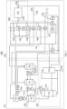
- FIG. 1 shows a process and facility for making hydrogen peroxide.
- the process for making hydrogen peroxide using an anthraquinone process comprises the step (a) hydrogenating a working solution, said working solution comprising an alkylanthraquinone, an alkyltetrahydroanthraquinone or both, contact said working solution with compressed hydrogen in a hydrogenator to provide a hydrogenated working solution comprising an alkylanthrahydroquinone, an alkyltetrahydroanthrahydroquinone or both.
- the working solution preferably comprises both 2-alkylanthraquinones and the corresponding 2-alkyltetrahydroanthraquinones and the ratio of 2-alkyltetrahydroanthraquinones plus 2-alkyltetrahydroanthrahydroquinones to 2-alkylanthraquinones plus 2-alkylanthrahydroquinones is preferably maintained in the range of from 1 to 20 by adjusting the conditions of the hydrogenating step and of regenerating steps used in the anthraquinone process.
- the working solution can also comprise at least one solvent for dissolving the quinone(s) and the hydroquinone(s).
- the working solution preferably comprises a mixture of alkylbenzenes having 9 or 10 carbon atoms as solvent for anthraquinones and at least one polar solvent selected from diisobutylcarbinol (DiBC), methylcyclohexylacetate (MCA), trioctylphosphate (TOP), tetrabutylurea (TBU) and N-octylcaprolactam as solvent for anthrahydroquinones.
- DiBC, MCA, TOP and TBU are preferred and TOP is most preferred.
- the working solution is circulating through the facility or process. In other words, the working solution should be resupplied, preferably through a buffer tank and pumped by a working solution pump, to the hydrogenator after the extraction from the hydrogen peroxide.
- step a all or a part of the quinones are converted to the corresponding hydroquinones.
- the hydrogenation is typically carried out in the presence of a heterogeneous hydrogenation catalyst.
- All hydrogenation catalysts known from the prior art for the anthraquinone cyclic process can be used as catalysts in the hydrogenation step.
- Noble metal catalysts containing palladium as the principal component are preferred.
- the catalysts can be used as a fixed bed catalyst or as a suspended catalyst and suspended catalysts can be either unsupported catalysts, such as palladium black, or supported catalysts, with suspended supported catalysts being preferred.
- SiO 2 , TiO 2 , Al 2 O 3 and mixed oxides thereof, as well as zeolites, BaSO 4 or polysiloxanes, can be used as support materials for fixed-bed catalysts or supported suspended catalysts, with Al 2 O 3 and sodium aluminum silicate being preferred.
- Catalysts in the form of monolithic or honeycombed moldings, the surface of which is coated with the noble metal, can also be used.
- Hydrogenation can be carried out in bubble column reactors, stirred-tank reactors, tube reactors, fixed-bed reactors, loop reactors or gas-lift reactors which can be equipped with devices for distributing hydrogen gas in the working solution, such as static mixers or injection nozzles.
- a bubble column with a recycle and injection of hydrogen gas at the column bottom is used, such as described in WO 2010/139728 and in Ullmann's Encyclopedia of Industrial Chemistry, online edition, entry "Hydrogen Peroxide", DOI: 10.1002/14356007.a13_443.pub3, pages 13-14 and Fig. 8.
- Hydrogenation is preferably carried out at a temperature of from 20 to 100°C, more preferably 45 to 75°C, and a pressure of from 0.1 MPa to 1 MPa, more preferably 0.2 MPa to 0.5 MPa.
- the hydrogenation is preferably performed in such a way that most of the hydrogen introduced into the hydrogenation reactor, preferably more than 90 wt.-%, such as more than 95 wt.-%, 80 to 90 wt.-%, 80 to 95 wt.-%, based on the total weight of hydrogen, is consumed in a single pass through the reactor.
- the ratio between hydrogen and working solution fed to the hydrogenation reactor is preferably chosen to convert between 30 and 80 % of the quinones to the corresponding hydroquinones.
- the hydrogenator of the facility of the present invention is configured for hydrogenating a working solution which contains an alkylanthraquinone, an alkyltetrahydroanthraquinone or both, with hydrogen, such as compressed hydrogen.
- the hydrogenator of the facility of the invention may be of any type known from the prior art for hydrogenating a working solution comprising an alkylanthraquinone, an alkyltetrahydroanthraquinone or both.
- the hydrogenator may comprise a bubble column reactor, a stirred-tank reactor, a tube reactor, a fixed-bed reactor, a loop reactor or a gas-lift reactor for carrying out the hydrogenation reaction, depending on whether a suspended hydrogenation catalyst or a fixed bed hydrogenation catalyst shall be used.
- the hydrogenator preferably comprises a bubble column with a recycle and injection of hydrogen gas at the column bottom for use with a suspended catalyst as known from WO 2010/139728 and Ullmann's Encyclopedia of Industrial Chemistry, online edition, entry "Hydrogen Peroxide", DOI: 10.1002/14356007.a13_443.pub3, pages 13-14 and Fig. 8.
- the hydrogenator preferably comprises a heat exchanger for removing the heat of reaction from the working solution, preferably a heat exchanger arranged inside the hydrogenation reactor.
- the hydrogenator typically also comprises a separator for separating catalyst from the working solution and returning it to the hydrogenation reactor, such as a filter, which may operate by cross-flow filtration or dead-end filtration.
- the hydrogenator may also comprise a hydrogen compressor for carrying out hydrogenation at a pressure higher than the pressure provided by the source of the hydrogen feed.
- the hydrogenator may further comprise a separator for separating non-reacted hydrogen gas from the hydrogenated working solution and recycling it to the hydrogenation reactor. If such a separator is present, the hydrogenator preferably also comprises a recycle compressor for recycling the non-reacted hydrogen gas.
- step b) of the process of the invention hydrogenated working solution obtained in step a) is oxidized with an oxygen containing gas in an oxidation reactor to provide an oxidized working solution comprising hydrogen peroxide and an alkylanthraquinone, an alkyltetrahydroanthraquinone or both.
- the oxygen containing gas is preferably air or air enriched with oxygen. All oxidation reactors known from the prior art for the anthraquinone process can be used for the oxidation, bubble columns operated in counter-current being preferred.
- the bubble column can be free from internal devices, but preferably contains distribution devices in the form of packings or sieve plates, most preferably sieve plates in combination with internal coolers.
- Oxidation is preferably carried out at a temperature of from 30 to 70°C, more preferably from 40 to 60°C. Oxidation is preferably performed with an excess of oxygen to convert more than 90 %, preferably more than 95 %, of the hydroquinones to the quinone form.
- the oxidation reactor of the facility of the present invention is configured for oxidizing hydrogenated working solution with an oxygen containing gas.
- the oxidation reactor comprises an oxidation reactor which may be of any type known from the prior art for oxidizing a hydrogenated working solution comprising an alkylanthrahydroquinone, an alkyltetrahydroanthrahydroquinone or both.
- a bubble column which is preferably operated in counter-current, is used as oxidation reactor.
- the bubble column can be free from internal devices, but preferably contains distribution devices in the form of packings or sieve plates, most preferably sieve plates in combination with internal heat exchangers.
- the oxidation reactor preferably comprises a demister for separating droplets entrained in the off-gas leaving the oxidation reactor.
- Extraction is preferably carried out in a counter-current continuous extraction column, sieve-plate columns being most preferred.
- the aqueous hydrogen peroxide solution obtained by extraction may also be purified for removing working solution components, preferably by washing with a solvent, which is preferably a solvent comprised in the working solution.
- the extracted oxidized working solution (i.e. working solution) is typically recycled to step a) for operating a cyclic anthraquinone process.
- the extraction in step (c) further comprises the provision of the working solution extracted in step (c) and the transfer of the working solution, comprising an alkylanthraquinone, an alkyltetrahydroanthraquinone or both, preferably via a buffer tank and a working solution pump, to the hydrogenator in which the working solution is hydrogenated in order to provide the hydrogenated working solution according to step (a).
- the extracted working solution of step c) is preferably dried in a dryer before it is recycled, preferably via a buffer tank and a working solution pump, to hydrogenating step a).
- Drying of the extracted working solution is preferably carried out by evaporating water from the working solution at a temperature of from 30 to 110 °C, preferably 40 to 75 °C and a pressure of from 10 to 300 mbar, preferably 20 to 100 mbar.
- Such drying of extracted working solution at reduced pressure is preferably carried out as described in WO 03/070632 on page 8, line 24 to page 8, line 3.
- the unit for producing hydrogen peroxide preferably further comprises a dryer for reducing the water content of the extracted working solution before recycling it to the hydrogenator. Any type of dryer known from the prior art to be suitable for removing water from the working solution of an anthraquinone process may be used.
- the dryer comprises a heater and the heater is subjected with medium pressure steam as described below.
- the extraction column of the facility of the present invention is configured for extracting hydrogen peroxide from oxidized working solution. Any type of extraction column known from the prior art for extracting hydrogen peroxide with an aqueous extractant from oxidized working solution containing dissolved hydrogen peroxide may be used.
- the extraction column is preferably a counter-current continuous extraction column, sieve-plate columns being most preferred.
- the facility (or plant) of the present invention may additionally comprise a hydrogen peroxide purification unit for purifying the extracted aqueous hydrogen peroxide solution by removing working solution components, preferably a unit for washing the aqueous hydrogen peroxide solution with a solvent.
- the aqueous solution of hydrogen peroxide can be concentrated to a concentration of from 45 to 90 wt.-%, such as 50 to 80 wt.-%, 50 to 75 wt.-%, 65 to 70 wt.-%, or 60 to 75 wt.-%, of hydrogen peroxide, based on the total weight of the concentrated aqueous hydrogen peroxide solution.
- the hydrogen peroxide can be concentrated at reduced pressure, preferably at a pressure of from 6000 to 13000 Pa (complies to 60 to 130 mbar), to prevent formation of explosive hydrogen peroxide vapors in the distillation.
- the distillation unit comprises an evaporator and a distillation column receiving vapor from the evaporator.
- Any type of evaporator and distillation column known from the prior art for concentrating an aqueous hydrogen peroxide solution may be used.
- the evaporator may be a distillation bottoms evaporator, which may be arranged separately from the distillation column or may be integrated into the distillation column, for example as disclosed in EP 0 419 406 A1 , Fig. 4 or in EP 0 835 680 A1 , Fig. 1 and 2.
- a separate thermosiphon evaporator passing a two-phase mixture of vapor and liquid to the distillation column may be used as distillation bottoms evaporator.
- the distillation unit may also comprise both a hydrogen peroxide feed evaporator and a distillation bottoms evaporator, with compressed vapor being passed to the hydrogen peroxide feed evaporator, for example as disclosed in Fig. 1 and 2 of WO 2012/025333 , or to the distillation bottoms evaporator or to both the hydrogen peroxide feed evaporator and the distillation bottoms evaporator.
- a preheater can also be subjected with the low-pressure steam, i.e. a steam flow with a pressure range of -0.8 barg to 3 barg and a temperature range of 60 to 185 °C, according to the invention.
- the distillation column may comprise trays or packings or a combination of both and preferably comprises structured packings to minimize pressure drop in the column.
- the distillation unit may also comprise a vapor compressor receiving overhead vapor from the distillation column and passing compressed vapor as heating medium to the evaporator.
- the vapor compressor may be a mechanical compressor, preferably a one stage mechanical compressor and is most preferably a water ring pump.
- the vapor compressor may alternatively be a gas jet pump and is preferably a steam driven ejector.
- the vapor compressor can be driven by the at least one steam turbine.
- the evaporator can be a falling film evaporator, single-stage evaporator, preferably a single-stage circulation evaporator, rising film evaporator, rising/falling film evaporator, or reboiler.
- a falling film evaporator is particularly preferred since the heat transfer efficiency allows the use of steam at below atmospheric pressure, such as -0.6 barg or -0.8 to 0 barg. Accordingly, it is particularly preferred to use a falling film evaporator that is subjected with steam derived from at least one steam turbine, wherein the steam has a pressure range of -0.8 barg to 0 barg and a temperature range of 60 to 185 °C
- the unit for producing hydrogen peroxide typically also comprises at least one buffer tank for storing aqueous hydrogen peroxide solution produced by the unit and at least one buffer tank for storing the circulating working solution.
- the process as well as the facility further comprises at least one steam turbine, wherein the at least one steam turbine drives at least one rotating equipment.
- the shaft-power of the turbines is used to drive the rotating equipment.
- the steam turbine is directly connected to rotating equipment via a drive shaft of the steam turbine and the rotating equipment. It is intended that most or all of the rotating equipment is operated by at least one steam turbine without an electrical drive.
- the rotating equipment can be any rotating equipment in the AO process, particularly as described in the description.
- the rotating equipment can be a compressor, a feed pump, such as oxidizer feed pump, or hydrogen feed pump, a working solution pump, a dryer, or a generator, such as an electric generator.
- the at least one steam turbine can be a backpressure steam turbine.
- Said steam flow with a pressure range of -0.8 barg to 3 barg and a temperature range of 60 to 185 °C can be regarded as low-pressure steam.
- the notation barg or bar(g) represents gauge pressure, i.e. pressure in bars above ambient or atmospheric pressure. Gauge pressure is zero-referenced against ambient air pressure. A negative sign represents a negative pressure and thus, below the ambient air pressure. Accordingly, -0.8 barg represents a vacuum that is below the ambient air pressure. Usually, the ambient air pressure is 1.013 bar (1 atm). A pressure of zero barg means that the pressure of the measured system equals the ambient air pressure.
- the at least one steam turbine can be one or more one steam turbine that provides the aforementioned steam flow. It is preferred that more than one, such as 2, 3, 4, 5, or 6, steam turbines are present in the facility and used in the process. It is also possible that the at least one steam turbine supplies two different steam flows, such as a low and medium pressurized steam.
- a steam flow having a medium pressurized steam refers to steam with a pressure range of 1 to 5 barg and a temperature range of 100 to 250 °C.
- the medium pressure steam can be subjected to other steam consumers that require said medium pressure steam in the AO process such as a heater or dryer.
- the present invention can comprise at least one steam turbine that provides at least two steam flows, a first steam flow providing steam with a pressure range of -0.8 barg to 3 barg, preferably -0.8 to 2 barg, -0.7 to 1 barg, -0.6 to 1 barg, -0.5 to 0.5 barg, - 0.8 to lower than 0 barg, -0.8 to 0 barg, or -0.6 to 0 barg, and a temperature range of 60 to 185 °C, preferably 60 to 185 °C, 60 to 185 °C, 80 to 170 °C, or 100 to 150 °C, to the evaporator (low or vacuum pressure steam) and a second steam flow providing steam with a pressure range of 1 to 5 barg, such as 1 to 4 barg, or 1 to 2 barg, and a temperature range of 100 to 250 °C, such as 100 to 220 °C, 110 to 200 °C, to other AO medium pressure steam consumers such as a heater or dryer (medium pressure steam consumers
- At least one steam turbine comprises a first steam turbine that provides a first steam flow comprising steam with a pressure range of -0.8 to 3 barg and a temperature range of 60 to 185 °C, wherein an outlet for the first steam flow is connected to the evaporator, and a second steam turbine that provides a second steam flow comprising steam with a pressure range of 1 to 5 barg and a temperature range of 100 to 250 °C to other AO steam consumers like a heater or dryer, wherein an outlet for the second steam flow is connected to a AO steam consumer such as a heater or dryer. It is desired that the pressure of the steam of the second steam flow is higher than the pressure of the steam of the first steam.
- the dryer can be supplied with medium pressure steam to remove remaining water from the working solution before being resupplied to the hydrogenator.
- the condensate derived from the steam flow and subjected to the dryer can be flashed in a chamber to produce a steam flow with a pressure range of -0.8 barg to 3 barg and a temperature range of 60 to 185 °C (low-pressure steam) that is supplied to the evaporator or to the conduit that is connected to the evaporator.
- a flash chamber that is subjected with condensate derived from medium pressure steam can produce low-pressure steam and thus, the energy consumption of the AO process is further reduced.
- a steam flow with a pressure range of 10 to 120 barg and a temperature range of 185 to 500 °C can drive at least one steam turbine, preferably all steam turbines.
- a superheated or saturated steam source provides a steam flow with a pressure range of 10 to 120 barg and a temperature range of 185 to 500 °C that drives at least one steam turbine, preferably all steam turbines.
- the superheated or saturated steam source can be a gas turbine heat recovery steam generator.
- the steam flow that is provided by the gas turbine heat recovery steam generator can drive an electrical generator.
- a steam inlet of at least one steam turbine can be connected with a conduit from a steam outlet of a gas turbine heat recovery steam generator.
- the present invention can comprise a steam reforming unit for producing hydrogen from natural gas, such as methane, which comprises a steam reformer and a steam generator as a superheated or saturated steam source which is heated by product gas exiting the steam reformer.
- the steam reforming unit typically also comprises a reactor for converting carbon monoxide to carbon dioxide by a water gas shift reaction, and a hydrogen separation unit which separates hydrogen from carbon dioxide.
- a hydrogen outlet of the steam reforming unit is connected by a conduit with an inlet of the hydrogenator for producing hydrogen peroxide, and a steam outlet of the steam generator is connected by a conduit with an inlet of at least one steam turbine. This allows to use energy generated in the steam reformer for heating the steam generator and thereby reduces the energy consumption of the facility and process.
- the at least one steam turbine provides a steam flow with a pressure range of -0.8 barg to 3 barg and a temperature range of 60 to 185 °C (low-pressure steam) to the evaporator via a low-pressure steam conduit system.
- More than one turbine can be connected to the low-pressure steam conduit system that distributes the low-pressure steam to the desired components such as the evaporator as described above.
- Turbines that provide medium pressure steam i.e. steam with a pressure range of 1 to 5 barg and a temperature range of 100 to 250 °C, can be connected to a medium pressure steam conduit system that distributes the medium pressure steam to the desired components such as a dryer or heater.
- Steam exiting the at least steam turbine such as a backpressure steam turbine, is used to supply heat to one or several distillation units, wherein the steam is provided at least to an evaporator that is present in the distillation unit.
- the steam exiting the steam turbine is used to supply heat to a distillation unit comprising the evaporator separating the solvent comprising water as an overhead product. Accordingly, the steam exiting the at least one steam turbine is used for supplying heat to a distillation unit for concentrating the extracted hydrogen peroxide.
- the air compressor may be any type known to be suitable for compressing air from ambient pressure to a pressure of from 0.11 to 1.6 MPa.
- the air compressor may be a reciprocating compressor, a rotary screw compressor, a centrifugal compressor or an axial compressor and is preferably a centrifugal compressor.
- a multistage compressor is used with coolers in between stages.
- the air compressor can be driven by the at least one steam turbine which is preferably directly connected to a drive shaft of the air compressor. An additional electric drive may also be connected to this drive shaft.
- the facility may contain one or more additional air compressors with outlets connected to the oxidation reactor for supplying compressed air and these additional air compressors may be driven electrically or by additional steam turbines or by a combination of both.
- the air is preferably compressed to a pressure of from 0.11 to 1.6 MPa, more preferably from 0.30 to 0.60 MPa.
- the compressed air is preferably cooled to a temperature in the range from 20 °C to 60 °C before introducing it into the oxidation reactor.
- the off-gas of the oxidation reactor can be used for at least one expansion turbine that also drives a rotating equipment.
- the oxidation reactor provides an oxidizer off-gas with a pressure range of 1 to 6 barg and a temperature range of 30 to 250 °C and the off-gas can drive at least one expansion turbine.
- an off-gas outlet of the oxidation reactor is connected with a conduit to an off-gas inlet of an expansion turbine.
- the facility preferably comprises a pressure control valve for adjusting the pressure of the low and/or medium pressure steam obtained by the at least one steam turbine, preferably a control valve upstream of the heat exchanger receiving steam form the steam outlet of the backpressure steam turbine, the control valve being arranged in a steam conduit bypassing the steam turbine.
- the facility preferably also comprises a flow control valve upstream of the heat exchanger receiving steam form the steam outlet of the at least one steam turbine.
- FIG. 1 refers to a process and facility for making hydrogen peroxide (100).
- the system according to claim 1 comprises a unit for producing hydrogen peroxide (101), and a unit for producing dry steam (102).
- a cyclic anthraquinone process is used for the production of hydrogen peroxide in the unit for producing hydrogen peroxide (101).
- the AO process comprises a hydrogenator (110), an oxidation reactor (111), an extractor (112), and a distillation unit (103).
- the distillation unit (103) comprises an evaporator (113) and a distillation column (114).
- the hydrogenator (110) comprises an inlet for supplying compressed hydrogen as well as an inlet for supplying working solution comprising alkylanthraquinone, an alkyltetrahydroanthraquinone or both.
- the working solution comprising alkylanthraquinone, an alkyltetrahydroanthraquinone or both is then hydrogenated in order to obtain a hydrogenated working solution comprising an alkylanthrahydroquinone, an alkyltetrahydroanthrahydroquinone or both.
- the oxidation reactor (111) comprises an inlet for the hydrogenated working solution comprising an alkylanthrahydroquinone, an alkyltetrahydroanthrahydroquinone or both, as well as an inlet for compressed oxygen containing gas, such as compressed air, compressed enriched oxygen containing gas, or compressed enriched oxygen containing air.
- compressed oxygen containing gas such as compressed air, compressed enriched oxygen containing gas, or compressed enriched oxygen containing air.
- the hydrogenated working solution comprising an alkylanthrahydroquinone, an alkyltetrahydroanthrahydroquinone or both, is then oxidized in the oxidation reactor (111) using compressed oxygen containing gas to obtain an oxidized working solution comprising hydrogen peroxide and an alkylanthraquinone, an alkyltetrahydroanthraquinone or both.
- the oxidation reactor (111) further comprises an outlet for the oxidized working solution that is then supplied, preferably via a working solution pump (117d) and a buffer tank (118b) to an extractor (112) and an outlet for oxidizer off-gas.
- the oxidizer off-gas is the compressed oxygen containing gas after the oxidation of the hydrogenated working solution.
- the oxidizer off-gas is preferably compressed.
- the extractor (112) comprises an inlet for receiving the oxidized working solution comprising hydrogen peroxide and an alkylanthraquinone, an alkyltetrahydroanthraquinone or both, as well as an inlet for receiving water (130). Accordingly, hydrogen peroxide from oxidized working solution is extracted (or separated) from the oxidized working solution to provide an aqueous hydrogen peroxide extract. Accordingly, a working solution comprising alkylanthraquinone, an alkyltetrahydroanthraquinone or both, is obtained that can be resupplied directly to the hydrogenator (110).
- the working solution comprising alkylanthraquinone, an alkyltetrahydroanthraquinone or both is supplied, preferably via a working solution pump (117c) using a buffer tank (118c), to a dryer (115) before supplying the working solution, preferably via a working solution pump (117d) using a buffer tank (118d), to the hydrogenator (110).
- the extractor (112) comprises an outlet for supplying the aqueous hydrogen peroxide extract to a distillation unit (103), particularly a distillation column (114).
- the aqueous hydrogen peroxide extract usually comprises 20 to 60 wt.-%, such as 25 to 55 wt.-%, 20 to 40 wt.-%, or 30 to 50 wt.-%, of hydrogen peroxide, based on the total weight percentage of the aqueous hydrogen peroxide extract.
- the dryer (115) can be supplied with a second steam flow with a pressure range of 1 to 5 barg, such as 1 to 4 barg, or 1 to 2 barg, and a temperature range of 100 to 250 °C, such as 100 to 220 °C, 110 to 200 °C (medium pressure steam).
- the working solution pumps (117a, 117b, 117c and 117d), can be driven by at least one steam turbine (120, 121, 122, 123, 124). At least one working solution pump can be used to circulate the working solution via buffer tanks (118a, 118b, 118c, 118d) from the hydrogenator (110) to the oxidation reactor (111), from the oxidation reactor (111) to the extractor (112) and from the extractor (112) directly back to the hydrogenator (110) or preferably from the extractor (112) to the dryer (115) and from the dryer (115) back to the hydrogenator (110).
- the distillation unit (103) in FIG. 1 comprises a distillation column (114) and an evaporator (113) arranged as a bottom evaporator.
- the aqueous hydrogen peroxide extract (feed) is transferred to the distillation column (114).
- the aqueous hydrogen peroxide extract is preheated before entering the distillation column (114).
- the preheating can be done by any means known in the art such as a heat exchanger, an evaporator, or a falling film evaporator as discussed above.
- the preheater can be heated by the steam flow with a pressure range of -0.8 barg to 3 barg and a temperature range of 60 to 185 °C produced by at least one steam turbine according to the invention.
- the vapor is condensed in a condenser (119) (top product).
- Non-condensable products can be discharged.
- Part of the top product is resupplied to the distillation column as a reflux and the remaining part of the top product or distillate can be collected (131) and resupplied to the extractor (112).
- the bottoms product is transferred to an evaporator (113) and a part of the bottom product is collected as concentrated aqueous hydrogen peroxide solution (132).
- the concentrated aqueous hydrogen peroxide solution (132) usually comprises 45 to 90 wt.-%, such as 50 to 80 wt.-%, 50 to 75 wt.-%, 65 to 70 wt.-%, or 60 to 75 wt.-%, of hydrogen peroxide, based on the total weight of the concentrated aqueous hydrogen peroxide solution.
- the evaporator (113) comprises an inlet for receiving the concentrated aqueous hydrogen peroxide solution and an inlet for receiving a steam flow with a pressure range of -0.8 barg to 3 barg, preferably -0.8 to 2 barg, -0.7 to 1 barg, -0.6 to 1 barg, -0.5 to 0.5 barg, or -0.6 to 0 barg, and a temperature range of 60 to 185 °C preferably 60 to 185 °C, 60 to 185 °C, 80 to 170 °C, or 100 to 150 °C.
- the steam flow supplied to the evaporator refers also to the first steam flow and/or low-pressure flow.
- the unit for producing dry steam (102) comprises a steam generating unit (108).
- the steam generating unit (108) comprises a superheated or saturated steam source (116) such as steam generator preferably a gas turbine heat recovery steam generator, dry steam boiler or waste heat boiler, which is heated by product gas exiting the superheated or saturated steam source.
- the superheated or saturated steam source (116) is connected with a high-pressure conduit system (140).
- Water (133) and/or condensate is transferred to a superheated or saturated steam source (116) for generating high-pressure steam.
- the generated high-pressure steam flow has a pressure in the range of 10 to 120 barg, preferably 20 to 50 barg, and a temperature in the range of 185 to 500 °C, preferably 200 to 400 °C.
- the high-pressure conduit system (140) provides high-pressure steam to at least one steam turbine (120, 121, 122, 123), such as a backpressure steam turbine (120, 121, 122, 123).
- the at least one steam turbine (120, 121, 122, 123) is able to reduce the pressure and/or temperature of the high-pressure steam flow provided by the superheated or saturated steam source (116) to obtain the desired steam flow comprising steam.
- at least one steam turbine (120, 121, 122, 123) provides a steam flow with a pressure range of -0.8 barg to 3 barg and a temperature range of 60 to 185 °C (low pressure) that is transferred via a conduit to the evaporator (113).
- the energy consumption and CO 2 emission of the process and facility according to the invention can be reduced.
- a falling film evaporator with a pressure of -0,8 barg to 0 barg and a temperature of 60 to 185 °C the decomposition of hydrogen peroxide can be reduced even more.
- the unit for producing medium pressure steam (104) comprises a steam turbine (120) that drives a first rotating equipment (125).
- the steam turbine (120) comprises an inlet for the high-pressure steam provided by the superheated or saturated steam source (116) and an outlet for the medium pressure steam.
- the medium pressure steam is distributed to a medium pressure steam conduit system (143) that supplies other AO process steam consumers, preferably the dryer (115), with medium pressure steam.
- the dryer (115) further comprises an outlet for the condensate derived from the supplied medium pressure steam.
- the condensate can be directly resupplied to the steam generating unit (108) or flashed in a chamber (150) to obtain low-pressure steam that can be supplied into the low-pressure steam conduit system (141). The remaining condensate can be resupplied to the steam generating unit (108).
- medium pressure steam can also be supplied to further components such as a heater.
- the pressure in the medium pressure steam conduit system (143) can be balanced by a lower pressure source or throttled from high pressure.
- said conduit system (143) can comprise a throttling valve connected to the high-pressure steam conduit system (140).
- the unit for producing low-pressure steam (106) comprises a steam turbine (122) that drives a compressor (127).
- the steam turbine (122) can also drive another rotating equipment.
- the steam turbine (122) comprises an inlet for the high-pressure steam provided by the superheated or saturated steam source (116) and an outlet for the low-pressure steam.
- the low-pressure steam is distributed to a low-pressure steam conduit system (141) that supplies the evaporator (113) with low-pressure steam.
- low-pressure steam has a pressure in the range of -0.8 to 3 barg and a temperature range of 60 to 185 °C. If the required pressure for the evaporator is low, such as -0.8 to 0 barg (vacuum pressure), the steam turbine (122) will provide more energy to the compressor (127).
- a falling film evaporator, or a raising/falling film evaporator in an AO process is particularly preferred since the evaporator can be supplied with low-pressure steam, wherein the pressure is -0.8 to 0 barg.
- the compressor (127) is used to compress oxygen containing gas (144), such as air (144) or enriched oxygen containing air (144) and transfer the compressed gas to the oxidation reactor (111).
- the pressure in the low-pressure steam conduit system (141) can be balanced by a lower pressure source, or throttled from high pressure.
- said conduit system (143) can comprise a throttling valve connected to the high-pressure steam conduit system (140).
- the unit for producing medium and low-pressure steam (105) comprises a steam turbine (121) that drives a hydrogen feed pump or compressor (126) or working solution pumps (117a, 117b, 117c, 117d).
- the steam turbine (121) can also drive another rotating equipment.
- the steam turbine (121) comprises an inlet for the high-pressure steam provided by the superheated or saturated steam source (116), an outlet for the low-pressure steam and an outlet for the medium pressure steam that are connected to the medium pressure steam conduit system (143) and the low-pressure steam conduit system (141), respectively.
- the hydrogen feed pump or compressor (126) is present within the hydrogen feed conduit (142) and transfers the hydrogen (134) to the hydrogenator (110).
- the working solution pumps (117a, 117b, 117c, 117d) are present in the unit for producing hydrogen peroxide (101) circulating the working solution from the hydrogenator (110) to the oxidation reactor (111), from the oxidation reactor (111) to the extractor (112), from the extractor (112) to the dryer (115) and from the dryer (115) back to the hydrogenator (110), preferably via buffer tanks (118a, 118b, 118c, 118d).
- the unit for producing low pressure using oxidizer off-gas (107) comprises a steam turbine (123), an expansion turbine (124) and a rotating equipment (128), such as a compressor, a generator, a hydrogenator feed pump, an oxidizer feed pump, or further working solution pumps.
- the steam turbine (123) comprises an inlet for the high-pressure steam provided by the superheated or saturated steam source (116), and an outlet for the low-pressure steam connected to the low-pressure steam conduit system (141).
- the expansion turbine (124) comprises an off-gas inlet for oxidizer off-gas.
- a conduit connects the off-gas inlet of the expansion turbine (124) and the off-gas outlet of the oxidation reactor (111).
- the oxidation reactor can provide an oxidizer off-gas that can be transferred to the expansion turbine (124).
- the oxidizer off-gas with a pressure range of 1 to 6 barg and a temperature range of 30 to 250 °C can drive at least one expansion turbine (124).
- At least one expansion turbine (124) and at least one steam turbine (123) can drive at least one rotating equipment (128).
- the combination of an expansion turbine (124) using the off-gas of the oxidizer as well as a steam turbine further allows to operate additional pumps in the AO process so that energy input, e.g. electric input and CO 2 emission, can be further reduced.
- the total consumption of energy for producing steam from natural gas and for the shaft power by electrical motor is 77,95 MW.
- the consumption of electrical energy only for the shaft power for electrical motors is 19,35 MW.
- the overall CO 2 emission is 207,669 TCO 2 /yr.
- a steam turbine is used to provide steam with pressure of 3 barg and a temperature of 144 °C to a boiler as an evaporator in the distillation unit.
- the total consumption of energy for producing steam from natural gas and for the shaft power by electrical motor is 77,31 MW.
- the consumption of electrical energy only for the shaft power for electrical motors is 12,61 MW.
- the overall CO 2 emission is 177,874 TCO 2 /yr.
- a steam turbine is used to provide steam with a pressure of -0,.6 barg and a temperature of 80°C to a falling film evaporator instead of a boiler in the distillation unit.
- the total consumption of energy for producing steam from natural gas and for the shaft power by electrical motor is 77,01 MW.
- the consumption of electrical energy only for the shaft power for electrical motors is 8,91 MW.
- the overall CO 2 emission is 161,508 TCO 2 /yr.
- the off-gas from the oxidation reactor is used by an expansion turbine which is connected to a steam turbine, providing steam with a pressure of -0,6 barg and a temperature of 80°C to a falling film evaporator. Both turbines are connected with a drive shafts to drive an air compressor.
- the total consumption of energy for producing steam from natural gas and for the shaft power by electrical motor is 73,51 MW.
- the consumption of electrical energy only for the shaft power for electrical motors is 5,41 MW.
- the overall CO 2 emission is 140,928 TCO 2 /yr.
Landscapes
- Chemical & Material Sciences (AREA)
- Organic Chemistry (AREA)
- Chemical Kinetics & Catalysis (AREA)
- Inorganic Chemistry (AREA)
- Organic Low-Molecular-Weight Compounds And Preparation Thereof (AREA)
- Treating Waste Gases (AREA)
- Gas Separation By Absorption (AREA)
Claims (15)
- Procédé de fabrication de peroxyde d'hydrogène, comprenant les étapes :(a) hydrogénation d'une solution de travail, ladite solution de travail comprenant une alkylanthraquinone, une alkyltétrahydroanthraquinone ou les deux, la mise en contact de ladite solution de travail avec de l'hydrogène comprimé dans un hydrogénateur (110) pour fournir une solution de travail hydrogénée comprenant une alkylanthrahydroquinone, une alkyltétrahydroanthrahydroquinone ou les deux,(b) oxydation de ladite solution de travail hydrogénée obtenue à l'étape a) avec un gaz contenant de l'oxygène comprimé, tel que de l'air comprimé ou de l'oxygène enrichi comprimé contenant de l'air, dans un réacteur d'oxydation (111) pour fournir une solution de travail oxydée comprenant du peroxyde d'hydrogène et une alkylanthraquinone, une alkyltétrahydroanthraquinone ou les deux,(c) extraction de peroxyde d'hydrogène d'une solution de travail oxydée obtenue à l'étape b) pour fournir un extrait aqueux de peroxyde d'hydrogène, et(d) concentration de l'extrait aqueux de peroxyde d'hydrogène obtenu à l'étape c) dans au moins une unité de distillation (103) comprenant un évaporateur (113) et une colonne de distillation (114), ladite colonne de distillation (114) recevant de la vapeur dudit évaporateur (113), pour fournir une solution aqueuse concentrée de peroxyde d'hydrogène,caractérisé en ce qu'au moins une turbine à vapeur (120, 121, 122, 123) entraîne au moins un équipement rotatif (125, 126, 127, 128, 117a-d), au moins une turbine à vapeur (120, 121, 122, 123) fournissant un écoulement de vapeur avec une plage de pression de -0,8 barg à 3 barg et une plage de température de 60 à 185 °C à l'évaporateur (113).
- Procédé selon la revendication 1, dans lequel l'écoulement de vapeur avec une plage de pression de - 0,8 barg à 0 barg et une plage de température de 60 à 185 °C est utilisé pour alimenter en chaleur un évaporateur à film tombant ou un évaporateur à film montant et/ou un évaporateur à film tombant/montant.
- Procédé selon la revendication 1, dans lequel un écoulement de vapeur avec une plage de pression de 10 à 120 barg et une plage de température de 185 à 500 °C entraîne au moins une turbine à vapeur (120, 121, 122, 123), préférablement toutes les turbines à vapeur (120, 121, 122, 123), préférablement une source de vapeur surchauffée ou saturée (116), préférablement un générateur de vapeur fournit un écoulement de vapeur avec une plage de pression de 10 à 120 barg et une plage de température de 185 à 500 °C, ledit écoulement de vapeur entraîne l'au moins une turbine à vapeur (120, 121, 122, 123), préférablement toutes les turbines à vapeur (120, 121, 122, 123).
- Procédé selon l'une quelconque des revendications précédentes, dans lequel au moins une turbine à vapeur (120, 121, 122, 123) fournissant au moins deux écoulements de vapeur, un premier écoulement de vapeur fournit de la vapeur avec une plage de pression de -0,8 à 3 barg et une plage de température de 60 à 185 °C à l'évaporateur et un deuxième écoulement de vapeur fournit de la vapeur avec une plage de pression de 1 à 5 barg et une plage de température de 100 à 250 °C à un dispositif de chauffage ou de séchage (115).
- Procédé selon la revendication 4, dans lequel le deuxième écoulement de vapeur fournit de la vapeur pour chauffer des granulés solides, en particulier du charbon actif ou de l'oxyde d'aluminium.
- Procédé selon l'une quelconque des revendications précédentes, dans lequel le réacteur d'oxydation (111) fournit un gaz de dégagement d'oxydant, le gaz de dégagement d'oxydant avec une plage de pression de 1 à 6 barg et une plage de température de 30 à 250 °C entraînant au moins une turbine de détente (124), et/ou au moins une turbine de détente (124) et au moins une turbine à vapeur (120, 121, 122, 123) entraînant au moins un équipement rotatif (125, 126, 127, 128, 117a-d).
- Installation pour produire du peroxyde d'hydrogène par un procédé d'anthraquinone comprenant :(a) un fluide de travail, préférablement un fluide de travail en circulation, comprenant une alkylanthraquinone, une alkyltétrahydroanthraquinone ou les deux,(b) un hydrogénateur (110) pour hydrogéner la solution de travail, afin de fournir une solution de travail hydrogénée,(c) un oxydant pour oxyder la solution de travail hydrogénée avec un gaz contenant de l'oxygène, ledit oxydant comprenant un réacteur d'oxydation (111) et un compresseur de gaz (127) pour introduire ledit gaz contenant de l'oxygène comprimé dans le réacteur d'oxydation (111), afin de fournir une solution de travail oxydée,(d) un extracteur (112) pour extraire le peroxyde d'hydrogène de la solution de travail oxydée afin de fournir un extrait aqueux de peroxyde d'hydrogène, et(e) une unité de distillation (103) pour concentrer l'extrait aqueux de peroxyde d'hydrogène afin de fournir une solution concentrée de peroxyde d'hydrogène, ladite unité de distillation (103) comprenant une colonne de distillation (114) et un évaporateur (113),caractérisée en ce que l'installation comprend au moins une turbine à vapeur (120, 121, 122, 123), la turbine à vapeur (120, 121, 122, 123) pouvant être soumise à de la vapeur, au moins un équipement rotatif (125, 126, 127, 128, 117a-d) pouvant être entraîné par au moins une turbine à vapeur (120, 121, 122, 123), une sortie de vapeur de la turbine à vapeur (120, 121, 122, 123) étant raccordée avec un conduit (141) à une entrée de vapeur de l'évaporateur (113).
- Installation selon la revendication 7, dans laquelle une entrée de vapeur d'au moins une turbine à vapeur (120, 121, 122, 123) est raccordée avec un conduit (140) à partir d'une sortie de vapeur d'une source de vapeur surchauffée ou saturée (116).
- Installation selon l'une quelconque des revendications 7 ou 8, dans laquelle un générateur électrique peut être entraîné par la source de vapeur surchauffée ou saturée (116).
- Installation selon l'une quelconque des revendications 7 à 9, dans laquelle au moins une turbine à vapeur (121) a une entrée de vapeur et deux sorties de vapeur.
- Installation selon la revendication 10, dans laquelle au moins une sortie de vapeur d'au moins une turbine à vapeur (120, 121, 122, 123) est raccordée avec un conduit (141, 143) à une entrée de vapeur d'un dispositif de chauffage ou de séchage (115).
- Installation selon la revendication 10 ou la revendication 11, dans laquelle au moins une sortie de vapeur d'au moins une turbine à vapeur (120, 121, 122, 123) est raccordée avec un conduit à une entrée de vapeur d'un récipient contenant des granulats solides, en particulier du charbon actif ou de l'oxyde d'aluminium.
- Installation selon l'une quelconque des revendications 7 à 12, dans laquelle une sortie de gaz de dégagement du réacteur d'oxydation (111) est raccordée avec un conduit à une entrée de gaz de dégagement d'une turbine de détente (124), au moins un équipement rotatif (125, 126, 127, 128, 117a-d) peut être entraîné par au moins une turbine de détente (124) et au moins une turbine à vapeur (123).
- Installation selon l'une quelconque des revendications 9 à 13, dans laquelle l'évaporateur (113) est un évaporateur à film tombant (113), ou un évaporateur à film montant (113), et/ou un évaporateur montant/tombant de film (113), préférablement un évaporateur à film tombant (113).
- Utilisation d'au moins une turbine à vapeur (120, 121, 122, 123) qui entraîne au moins un équipement rotatif (125, 126, 127, 128, 117a-d) dans un procédé pour produire du peroxyde d'hydrogène par un procédé d'anthraquinone, l'au moins une turbine à vapeur fournissant un écoulement de vapeur avec une plage de pression de -0,8 barg à 3 barg et une plage de température de 60 à 185 °C à un évaporateur (113) pour concentrer un extrait aqueux de peroxyde d'hydrogène dans au moins une unité de distillation (103) comprenant l'évaporateur (113) afin d'obtenir une solution aqueuse concentrée de peroxyde d'hydrogène.
Applications Claiming Priority (2)
| Application Number | Priority Date | Filing Date | Title |
|---|---|---|---|
| EP21172999 | 2021-05-10 | ||
| PCT/EP2022/061473 WO2022238147A1 (fr) | 2021-05-10 | 2022-04-29 | Réseau de vapeur optimisé pour le procédé ao |
Publications (2)
| Publication Number | Publication Date |
|---|---|
| EP4337603A1 EP4337603A1 (fr) | 2024-03-20 |
| EP4337603B1 true EP4337603B1 (fr) | 2025-04-09 |
Family
ID=76283524
Family Applications (1)
| Application Number | Title | Priority Date | Filing Date |
|---|---|---|---|
| EP22726122.9A Active EP4337603B1 (fr) | 2021-05-10 | 2022-04-29 | Réseau de vapeur optimisé pour le procédé ao |
Country Status (11)
| Country | Link |
|---|---|
| US (1) | US20240239658A1 (fr) |
| EP (1) | EP4337603B1 (fr) |
| KR (1) | KR20240005739A (fr) |
| CN (1) | CN117295684A (fr) |
| AU (1) | AU2022274987A1 (fr) |
| CA (1) | CA3218129A1 (fr) |
| CL (1) | CL2023003325A1 (fr) |
| DK (1) | DK4337603T3 (fr) |
| FI (1) | FI4337603T3 (fr) |
| HU (1) | HUE071737T2 (fr) |
| WO (1) | WO2022238147A1 (fr) |
Family Cites Families (10)
| Publication number | Priority date | Publication date | Assignee | Title |
|---|---|---|---|---|
| BE756015A (fr) * | 1969-09-10 | 1971-02-15 | Degussa | Procede pour la preparation de peroxyde d'hydrogene (e) |
| BE791535A (fr) * | 1971-11-18 | 1973-05-17 | Oxysynthese | Procede perfectionne de fabrication de peroxyde d'hydrogene |
| US5171407A (en) | 1989-09-22 | 1992-12-15 | Sulzer Brothers Limited | Distillation plant for producing hydrogen peroxide |
| BE1005199A3 (fr) * | 1991-08-27 | 1993-05-25 | Interox Internat Sa | Procede pour l'obtention de solutions aqueuses de peroxyde d'hydrogene. |
| DE59610305D1 (de) | 1996-10-09 | 2003-05-08 | Sulzer Chemtech Ag Winterthur | Destillationsanlage |
| DE10207407A1 (de) | 2002-02-21 | 2003-09-04 | Degussa | Verfahren zur Herstellung von Wasserstoffperoxid |
| SE531872C2 (sv) * | 2006-01-24 | 2009-09-01 | Bengt H Nilsson Med Ultirec Fa | Förfarande för stegvis energiomvandling |
| EP2437877B1 (fr) | 2009-06-05 | 2017-12-20 | Solvay Sa | Processus de séparation de liquide à partir d'un mélange à phases multiples |
| DE102009030960A1 (de) * | 2009-06-29 | 2010-12-30 | Gea Wiegand Gmbh | Anlage zur Herstellung von Alkohol aus Zuckerrohr |
| DE102010039748A1 (de) * | 2010-08-25 | 2012-03-01 | Evonik Degussa Gmbh | Verfahren zum Konzentrieren von wässriger Wasserstoffperoxidlösung |
-
2022
- 2022-04-29 AU AU2022274987A patent/AU2022274987A1/en active Pending
- 2022-04-29 KR KR1020237038290A patent/KR20240005739A/ko active Pending
- 2022-04-29 FI FIEP22726122.9T patent/FI4337603T3/fi active
- 2022-04-29 DK DK22726122.9T patent/DK4337603T3/da active
- 2022-04-29 CA CA3218129A patent/CA3218129A1/fr active Pending
- 2022-04-29 EP EP22726122.9A patent/EP4337603B1/fr active Active
- 2022-04-29 US US18/559,786 patent/US20240239658A1/en active Pending
- 2022-04-29 WO PCT/EP2022/061473 patent/WO2022238147A1/fr not_active Ceased
- 2022-04-29 CN CN202280034288.7A patent/CN117295684A/zh active Pending
- 2022-04-29 HU HUE22726122A patent/HUE071737T2/hu unknown
-
2023
- 2023-11-08 CL CL2023003325A patent/CL2023003325A1/es unknown
Also Published As
| Publication number | Publication date |
|---|---|
| CN117295684A (zh) | 2023-12-26 |
| EP4337603A1 (fr) | 2024-03-20 |
| CL2023003325A1 (es) | 2024-06-14 |
| KR20240005739A (ko) | 2024-01-12 |
| HUE071737T2 (hu) | 2025-09-28 |
| AU2022274987A1 (en) | 2023-12-21 |
| CA3218129A1 (fr) | 2022-11-17 |
| DK4337603T3 (da) | 2025-06-30 |
| FI4337603T3 (fi) | 2025-07-04 |
| WO2022238147A1 (fr) | 2022-11-17 |
| US20240239658A1 (en) | 2024-07-18 |
Similar Documents
| Publication | Publication Date | Title |
|---|---|---|
| KR101811561B1 (ko) | 복합화학공정 내의 증발스팀재압축기를 이용한 에너지 재활용 시스템 | |
| EP3915933B1 (fr) | Dispositif et procédé de production de peroxyde d'hydrogène par un processus d'anthraquinone | |
| JPS589042B2 (ja) | 水の分解方法 | |
| CN1048226C (zh) | 生产过氧化氢的方法及装置 | |
| EP4197993A1 (fr) | Installation et procédé intégrés pour la production de méthanol à partir de dioxyde de carbone et d'hydrogène | |
| US20220298128A1 (en) | Integrated process and plant for making styrene and propene oxide | |
| EP4337603B1 (fr) | Réseau de vapeur optimisé pour le procédé ao | |
| EP4219407B1 (fr) | Système et procédé d'amélioration de la qualité de l'eau d'une tour de déshydratation d'un appareil de production d'acide téréphtalique purifié | |
| CN113443962A (zh) | 用于生产纯甲醇的方法和设备 | |
| JP3291749B2 (ja) | 芳香族カルボン酸の製造方法 | |
| JPS61254177A (ja) | エタノ−ル含有液からのエタノ−ル抽出法 | |
| CN119118796A (zh) | 一种使用dmac分离异丙醇-异辛烷的方法及工艺 | |
| EP4337645B1 (fr) | Installation intégrée et procédé intégré de fabrication d'oxyde de propène | |
| RU2852724C2 (ru) | Комплексная установка и комплексный способ производства оксида пропилена | |
| EP4261327A1 (fr) | Installation et procédé d'acide nitrique avec système de récupération de chaleur | |
| CN113816830A (zh) | 膜分离降低醋酸甲酯加氢反应器中甲醇含量的方法和系统 | |
| EP4472926B1 (fr) | Refroidissement d'absorption d'ammoniac vert | |
| CN120903606A (zh) | 一种压缩循环供热重水精馏工艺 |
Legal Events
| Date | Code | Title | Description |
|---|---|---|---|
| STAA | Information on the status of an ep patent application or granted ep patent |
Free format text: STATUS: UNKNOWN |
|
| STAA | Information on the status of an ep patent application or granted ep patent |
Free format text: STATUS: THE INTERNATIONAL PUBLICATION HAS BEEN MADE |
|
| PUAI | Public reference made under article 153(3) epc to a published international application that has entered the european phase |
Free format text: ORIGINAL CODE: 0009012 |
|
| STAA | Information on the status of an ep patent application or granted ep patent |
Free format text: STATUS: REQUEST FOR EXAMINATION WAS MADE |
|
| 17P | Request for examination filed |
Effective date: 20231128 |
|
| AK | Designated contracting states |
Kind code of ref document: A1 Designated state(s): AL AT BE BG CH CY CZ DE DK EE ES FI FR GB GR HR HU IE IS IT LI LT LU LV MC MK MT NL NO PL PT RO RS SE SI SK SM TR |
|
| DAV | Request for validation of the european patent (deleted) | ||
| DAX | Request for extension of the european patent (deleted) | ||
| GRAP | Despatch of communication of intention to grant a patent |
Free format text: ORIGINAL CODE: EPIDOSNIGR1 |
|
| STAA | Information on the status of an ep patent application or granted ep patent |
Free format text: STATUS: GRANT OF PATENT IS INTENDED |
|
| INTG | Intention to grant announced |
Effective date: 20241104 |
|
| GRAS | Grant fee paid |
Free format text: ORIGINAL CODE: EPIDOSNIGR3 |
|
| GRAA | (expected) grant |
Free format text: ORIGINAL CODE: 0009210 |
|
| STAA | Information on the status of an ep patent application or granted ep patent |
Free format text: STATUS: THE PATENT HAS BEEN GRANTED |
|
| AK | Designated contracting states |
Kind code of ref document: B1 Designated state(s): AL AT BE BG CH CY CZ DE DK EE ES FI FR GB GR HR HU IE IS IT LI LT LU LV MC MK MT NL NO PL PT RO RS SE SI SK SM TR |
|
| P01 | Opt-out of the competence of the unified patent court (upc) registered |
Free format text: CASE NUMBER: APP_10640/2025 Effective date: 20250304 |
|
| REG | Reference to a national code |
Ref country code: GB Ref legal event code: FG4D |
|
| REG | Reference to a national code |
Ref country code: CH Ref legal event code: EP |
|
| REG | Reference to a national code |
Ref country code: DE Ref legal event code: R096 Ref document number: 602022012961 Country of ref document: DE |
|
| REG | Reference to a national code |
Ref country code: IE Ref legal event code: FG4D |
|
| PGFP | Annual fee paid to national office [announced via postgrant information from national office to epo] |
Ref country code: NL Payment date: 20250418 Year of fee payment: 4 |
|
| REG | Reference to a national code |
Ref country code: NL Ref legal event code: FP |
|
| REG | Reference to a national code |
Ref country code: DK Ref legal event code: T3 Effective date: 20250627 |
|
| REG | Reference to a national code |
Ref country code: FI Ref legal event code: FGE |
|
| PGFP | Annual fee paid to national office [announced via postgrant information from national office to epo] |
Ref country code: FI Payment date: 20250627 Year of fee payment: 4 |
|
| PGFP | Annual fee paid to national office [announced via postgrant information from national office to epo] |
Ref country code: DE Payment date: 20250422 Year of fee payment: 4 |
|
| PGFP | Annual fee paid to national office [announced via postgrant information from national office to epo] |
Ref country code: NO Payment date: 20250424 Year of fee payment: 4 |
|
| PGFP | Annual fee paid to national office [announced via postgrant information from national office to epo] |
Ref country code: BE Payment date: 20250418 Year of fee payment: 4 |
|
| REG | Reference to a national code |
Ref country code: SE Ref legal event code: TRGR |
|
| PGFP | Annual fee paid to national office [announced via postgrant information from national office to epo] |
Ref country code: AT Payment date: 20250721 Year of fee payment: 4 |
|
| PGFP | Annual fee paid to national office [announced via postgrant information from national office to epo] |
Ref country code: SE Payment date: 20250618 Year of fee payment: 4 |
|
| PGFP | Annual fee paid to national office [announced via postgrant information from national office to epo] |
Ref country code: HU Payment date: 20250603 Year of fee payment: 4 |
|
| REG | Reference to a national code |
Ref country code: AT Ref legal event code: MK05 Ref document number: 1783426 Country of ref document: AT Kind code of ref document: T Effective date: 20250409 |
|
| REG | Reference to a national code |
Ref country code: HU Ref legal event code: AG4A Ref document number: E071737 Country of ref document: HU |
|
| PG25 | Lapsed in a contracting state [announced via postgrant information from national office to epo] |
Ref country code: PT Free format text: LAPSE BECAUSE OF FAILURE TO SUBMIT A TRANSLATION OF THE DESCRIPTION OR TO PAY THE FEE WITHIN THE PRESCRIBED TIME-LIMIT Effective date: 20250811 Ref country code: ES Free format text: LAPSE BECAUSE OF FAILURE TO SUBMIT A TRANSLATION OF THE DESCRIPTION OR TO PAY THE FEE WITHIN THE PRESCRIBED TIME-LIMIT Effective date: 20250409 |
|
| PGFP | Annual fee paid to national office [announced via postgrant information from national office to epo] |
Ref country code: DK Payment date: 20250704 Year of fee payment: 4 |
|
| REG | Reference to a national code |
Ref country code: LT Ref legal event code: MG9D |
|
| PG25 | Lapsed in a contracting state [announced via postgrant information from national office to epo] |
Ref country code: GR Free format text: LAPSE BECAUSE OF FAILURE TO SUBMIT A TRANSLATION OF THE DESCRIPTION OR TO PAY THE FEE WITHIN THE PRESCRIBED TIME-LIMIT Effective date: 20250710 |
|
| PG25 | Lapsed in a contracting state [announced via postgrant information from national office to epo] |
Ref country code: PL Free format text: LAPSE BECAUSE OF FAILURE TO SUBMIT A TRANSLATION OF THE DESCRIPTION OR TO PAY THE FEE WITHIN THE PRESCRIBED TIME-LIMIT Effective date: 20250409 |
|
| PG25 | Lapsed in a contracting state [announced via postgrant information from national office to epo] |
Ref country code: BG Free format text: LAPSE BECAUSE OF FAILURE TO SUBMIT A TRANSLATION OF THE DESCRIPTION OR TO PAY THE FEE WITHIN THE PRESCRIBED TIME-LIMIT Effective date: 20250409 |
|
| PG25 | Lapsed in a contracting state [announced via postgrant information from national office to epo] |
Ref country code: AT Free format text: LAPSE BECAUSE OF FAILURE TO SUBMIT A TRANSLATION OF THE DESCRIPTION OR TO PAY THE FEE WITHIN THE PRESCRIBED TIME-LIMIT Effective date: 20250409 Ref country code: HR Free format text: LAPSE BECAUSE OF FAILURE TO SUBMIT A TRANSLATION OF THE DESCRIPTION OR TO PAY THE FEE WITHIN THE PRESCRIBED TIME-LIMIT Effective date: 20250409 |
|
| PG25 | Lapsed in a contracting state [announced via postgrant information from national office to epo] |
Ref country code: RS Free format text: LAPSE BECAUSE OF FAILURE TO SUBMIT A TRANSLATION OF THE DESCRIPTION OR TO PAY THE FEE WITHIN THE PRESCRIBED TIME-LIMIT Effective date: 20250709 |
|
| PG25 | Lapsed in a contracting state [announced via postgrant information from national office to epo] |
Ref country code: IS Free format text: LAPSE BECAUSE OF FAILURE TO SUBMIT A TRANSLATION OF THE DESCRIPTION OR TO PAY THE FEE WITHIN THE PRESCRIBED TIME-LIMIT Effective date: 20250809 |
|
| PG25 | Lapsed in a contracting state [announced via postgrant information from national office to epo] |
Ref country code: LV Free format text: LAPSE BECAUSE OF FAILURE TO SUBMIT A TRANSLATION OF THE DESCRIPTION OR TO PAY THE FEE WITHIN THE PRESCRIBED TIME-LIMIT Effective date: 20250409 |
|
| REG | Reference to a national code |
Ref country code: CH Ref legal event code: H13 Free format text: ST27 STATUS EVENT CODE: U-0-0-H10-H13 (AS PROVIDED BY THE NATIONAL OFFICE) Effective date: 20251125 |
|
| PG25 | Lapsed in a contracting state [announced via postgrant information from national office to epo] |
Ref country code: LU Free format text: LAPSE BECAUSE OF NON-PAYMENT OF DUE FEES Effective date: 20250429 |
|
| REG | Reference to a national code |
Ref country code: DE Ref legal event code: R097 Ref document number: 602022012961 Country of ref document: DE |
|
| PG25 | Lapsed in a contracting state [announced via postgrant information from national office to epo] |
Ref country code: SM Free format text: LAPSE BECAUSE OF FAILURE TO SUBMIT A TRANSLATION OF THE DESCRIPTION OR TO PAY THE FEE WITHIN THE PRESCRIBED TIME-LIMIT Effective date: 20250409 |
|
| PG25 | Lapsed in a contracting state [announced via postgrant information from national office to epo] |
Ref country code: CH Free format text: LAPSE BECAUSE OF NON-PAYMENT OF DUE FEES Effective date: 20250430 |
|
| PG25 | Lapsed in a contracting state [announced via postgrant information from national office to epo] |
Ref country code: CZ Free format text: LAPSE BECAUSE OF FAILURE TO SUBMIT A TRANSLATION OF THE DESCRIPTION OR TO PAY THE FEE WITHIN THE PRESCRIBED TIME-LIMIT Effective date: 20250409 |
|
| PG25 | Lapsed in a contracting state [announced via postgrant information from national office to epo] |
Ref country code: EE Free format text: LAPSE BECAUSE OF FAILURE TO SUBMIT A TRANSLATION OF THE DESCRIPTION OR TO PAY THE FEE WITHIN THE PRESCRIBED TIME-LIMIT Effective date: 20250409 |
|
| PG25 | Lapsed in a contracting state [announced via postgrant information from national office to epo] |
Ref country code: SK Free format text: LAPSE BECAUSE OF FAILURE TO SUBMIT A TRANSLATION OF THE DESCRIPTION OR TO PAY THE FEE WITHIN THE PRESCRIBED TIME-LIMIT Effective date: 20250409 |
|
| PG25 | Lapsed in a contracting state [announced via postgrant information from national office to epo] |
Ref country code: IT Free format text: LAPSE BECAUSE OF FAILURE TO SUBMIT A TRANSLATION OF THE DESCRIPTION OR TO PAY THE FEE WITHIN THE PRESCRIBED TIME-LIMIT Effective date: 20250409 |
|
| PG25 | Lapsed in a contracting state [announced via postgrant information from national office to epo] |
Ref country code: MC Free format text: LAPSE BECAUSE OF FAILURE TO SUBMIT A TRANSLATION OF THE DESCRIPTION OR TO PAY THE FEE WITHIN THE PRESCRIBED TIME-LIMIT Effective date: 20250409 |
|
| PLBE | No opposition filed within time limit |
Free format text: ORIGINAL CODE: 0009261 |
|
| STAA | Information on the status of an ep patent application or granted ep patent |
Free format text: STATUS: NO OPPOSITION FILED WITHIN TIME LIMIT |
|
| REG | Reference to a national code |
Ref country code: CH Ref legal event code: L10 Free format text: ST27 STATUS EVENT CODE: U-0-0-L10-L00 (AS PROVIDED BY THE NATIONAL OFFICE) Effective date: 20260218 |
|
| PG25 | Lapsed in a contracting state [announced via postgrant information from national office to epo] |
Ref country code: RO Free format text: LAPSE BECAUSE OF FAILURE TO SUBMIT A TRANSLATION OF THE DESCRIPTION OR TO PAY THE FEE WITHIN THE PRESCRIBED TIME-LIMIT Effective date: 20250409 |
|
| 26N | No opposition filed |
Effective date: 20260112 |
|
| PG25 | Lapsed in a contracting state [announced via postgrant information from national office to epo] |
Ref country code: IE Free format text: LAPSE BECAUSE OF NON-PAYMENT OF DUE FEES Effective date: 20250429 |
|
| PG25 | Lapsed in a contracting state [announced via postgrant information from national office to epo] |
Ref country code: FR Free format text: LAPSE BECAUSE OF NON-PAYMENT OF DUE FEES Effective date: 20250609 |