EP4337829B1 - Stopfmaschine zum verdichten der schotterbettung eines gleises - Google Patents
Stopfmaschine zum verdichten der schotterbettung eines gleises Download PDFInfo
- Publication number
- EP4337829B1 EP4337829B1 EP22722397.1A EP22722397A EP4337829B1 EP 4337829 B1 EP4337829 B1 EP 4337829B1 EP 22722397 A EP22722397 A EP 22722397A EP 4337829 B1 EP4337829 B1 EP 4337829B1
- Authority
- EP
- European Patent Office
- Prior art keywords
- lifting
- roller
- cylinder
- tamping machine
- tamping
- Prior art date
- Legal status (The legal status is an assumption and is not a legal conclusion. Google has not performed a legal analysis and makes no representation as to the accuracy of the status listed.)
- Active
Links
Images



Classifications
-
- E—FIXED CONSTRUCTIONS
- E01—CONSTRUCTION OF ROADS, RAILWAYS, OR BRIDGES
- E01B—PERMANENT WAY; PERMANENT-WAY TOOLS; MACHINES FOR MAKING RAILWAYS OF ALL KINDS
- E01B27/00—Placing, renewing, working, cleaning, or taking-up the ballast, with or without concurrent work on the track; Devices therefor; Packing sleepers
- E01B27/12—Packing sleepers, with or without concurrent work on the track; Compacting track-carrying ballast
- E01B27/13—Packing sleepers, with or without concurrent work on the track
- E01B27/16—Sleeper-tamping machines
- E01B27/17—Sleeper-tamping machines combined with means for lifting, levelling or slewing the track
-
- E—FIXED CONSTRUCTIONS
- E01—CONSTRUCTION OF ROADS, RAILWAYS, OR BRIDGES
- E01B—PERMANENT WAY; PERMANENT-WAY TOOLS; MACHINES FOR MAKING RAILWAYS OF ALL KINDS
- E01B35/00—Applications of measuring apparatus or devices for track-building purposes
-
- E—FIXED CONSTRUCTIONS
- E01—CONSTRUCTION OF ROADS, RAILWAYS, OR BRIDGES
- E01B—PERMANENT WAY; PERMANENT-WAY TOOLS; MACHINES FOR MAKING RAILWAYS OF ALL KINDS
- E01B2203/00—Devices for working the railway-superstructure
- E01B2203/10—Track-lifting or-lining devices or methods
-
- E—FIXED CONSTRUCTIONS
- E01—CONSTRUCTION OF ROADS, RAILWAYS, OR BRIDGES
- E01B—PERMANENT WAY; PERMANENT-WAY TOOLS; MACHINES FOR MAKING RAILWAYS OF ALL KINDS
- E01B2203/00—Devices for working the railway-superstructure
- E01B2203/12—Tamping devices
-
- E—FIXED CONSTRUCTIONS
- E01—CONSTRUCTION OF ROADS, RAILWAYS, OR BRIDGES
- E01B—PERMANENT WAY; PERMANENT-WAY TOOLS; MACHINES FOR MAKING RAILWAYS OF ALL KINDS
- E01B2203/00—Devices for working the railway-superstructure
- E01B2203/12—Tamping devices
- E01B2203/122—Tamping devices for straight track
-
- E—FIXED CONSTRUCTIONS
- E01—CONSTRUCTION OF ROADS, RAILWAYS, OR BRIDGES
- E01B—PERMANENT WAY; PERMANENT-WAY TOOLS; MACHINES FOR MAKING RAILWAYS OF ALL KINDS
- E01B2203/00—Devices for working the railway-superstructure
- E01B2203/12—Tamping devices
- E01B2203/125—Tamping devices adapted for switches or crossings
Definitions
- the invention relates to a tamping machine for compacting the ballast bed of a track, with tamping units for tamping a track, with a lifting and straightening device arranged between running gears, preferably in front of the tamping units in the working direction, for lifting and straightening tracks and switches, with at least one height-adjustable lifting roller and with at least one lifting hook that is height-adjustable independently thereof, wherein the lifting roller and the lifting hook are arranged on a common console that is guided so as to be displaceable transversely to the longitudinal axis of the tamping machine by means of an actuator.
- Switch tamping machines are machines for correcting the track position of switches and tracks.
- measuring systems are used which measure the actual track height, the actual track direction and the actual superelevation of the track during work and compare them with specified target values.
- the track grid is raised and aligned laterally until the difference between the specified target position and the actual position is zero.
- the switch is fixed in this spatial position by compacting the ballast under the sleepers with the help of a tamping unit.
- the track grid is raised and aligned using hydraulic lifting and straightening cylinders with proportional or servo control.
- a special feature of switches is a continuous track and a branching track.
- Trains are guided into the branch via so-called tongues or kept on the continuous main track.
- the so-called frog is located at the intersection point of the continuous track and the branching track.
- the railway wheel In the area of the frog, the railway wheel must be guided from the rail of the continuous track to the rail of the branching track.
- Guide rails are provided so that the wheel that is not guided in the interruption area rolls safely into the branch or into the continuous main track.
- the tamping units can be moved sideways and, because of the slanted long sleepers, the tamping units can be rotated.
- the tamping picks can also be designed to be at least partially pivotable.
- the machine operator controls the position of the tamping unit and, depending on the conditions and discretion, he selects the roller tongs or the lifting hook or the position of the lifting hook and the point of attachment of the latter on the rail head or the rail foot.
- the lifting device can also be moved in the longitudinal direction of the track. This is necessary when the lifting hook engages the rail foot - this is only possible in the area of the intermediate compartment - or when, due to an insulated joint, the roller tongs or the lifting hook cannot engage the rail head.
- roller clamp which is closed by rotating
- the roller clamp has to be manually adjusted if it becomes worn or if the rail head heights are different, and that the roller clamp is fixed in its position across the track. If the height of the roller clamp is not adjusted to the conditions, the straightening roller lifts off the rail by the existing play. This leads to undesirable stress on the rail head further up and easily leads to the straightening roller slipping and subsequent derailment.
- a further disadvantage is that, due to the spatial conditions, rotating roller clamps often have to be integrated into the lifting and straightening unit in such a way that accessibility is difficult. This increases the time required for maintenance work or repair work. Adjusting the roller in height requires a correspondingly large amount of time and expense.
- the lifting roller and lifting hook can be guided vertically and horizontally, i.e. transversely to the longitudinal axis of the tamping machine.
- the lifting hook and lifting roller are arranged on a common console and can be moved together with the console along a transverse guide.
- the lifting roller like the lifting hook, is lowered or raised vertically hydraulically using cylinders.
- the console is moved horizontally inwards towards the middle of the track to grip a rail head with the lifting roller or to grip the rail with the lifting hook.
- the lifting roller is then moved upwards until it rests on the underside of the rail head. This avoids dependence on wear of the roller or different rail head heights. It is no longer necessary to readjust the roller.
- lifting rollers and hooks are also arranged on a common console, which is mounted so that it can be moved transversely to the longitudinal axis of the machine.
- the lifting hooks can be adjusted to a higher level for the basic setting of the height and the lifting rollers are guided so that they can move around a swivel axis running in the longitudinal direction of the machine. Lifting rollers and hooks can be lifted together with the lifting device.
- the disadvantage of this design is that the lifting roller and lifting hook can only be moved vertically and horizontally. When tamping main tracks, speed is important. If the roller guided in this way remains in contact with the rail when moving forward quickly, it may hit raised rail fasteners, insulating joints or rail welding beads. Because the roller is guided purely horizontally, it cannot be forced open so quickly, which can cause damage to the roller, the lifting and straightening unit or the rail fasteners. Therefore, the roller is extended sideways far enough to avoid damage to raised small iron parts before the machine moves forward, and is then retracted again after the machine has stopped. This takes time.
- the roller clamp is only extended to the width of the rail head before the machine moves forward and then closed again when the machine comes to a standstill. This also takes time, which has a negative effect on the machine's performance, especially when tamping main tracks.
- a further disadvantage is that in order to reduce the travel, the lifting ring of the lifting roller may be made with reduced strength. This makes the lifting ring prone to breakage.
- the invention is therefore based on the object of finding an embodiment of the lifting and straightening device in which the lifting roller can move away quickly enough to avoid damage to the roller, the lifting and straightening device or the rail fastenings.
- the invention solves the problem in that the console is arranged on a guide carriage with which it can be moved transversely to the longitudinal axis of the tamping machine along a transverse guide and in that the console is mounted on the guide carriage with a swivel drive so that it can be swiveled about a swivel axis parallel to the longitudinal axis of the tamping machine.
- the lifting hook and lifting roller are mounted on the common console and can each be adjusted in height using a lifting drive.
- this console is designed to be rotatable in relation to the guide carriage, i.e. it can be swiveled around a swivel axis parallel to the longitudinal axis of the tamping machine. This retains the advantages of the vertical and horizontal positioning of the lifting roller and lifting hook. This means that it can be used perfectly in switches.
- the drive for the rotary movement of the lifting tool console is operated in a floating manner or with a low pressure force. If there is a rail joint or if welding beads occur, the lifting roller is simply forced on. The inclination of the roller also means that there is no conflict with the rail fastenings.
- Another advantage is that the lifting ring of the lifting roller can be made stronger due to the swiveling ability and is therefore no longer prone to breakage.
- the guide carriage can be moved along the cross guide transversely to the longitudinal axis of the tamping machine.
- the piston rods or cylinders of two hydraulic cylinders are supported on the console, which is pivotably mounted on the guide carriage around the longitudinal axis of the tamping machine.
- One hydraulic cylinder with a smaller stroke is used for vertical adjustment of the lifting roller.
- the other hydraulic cylinder with a longer stroke is intended for the lifting hook. The longer stroke is necessary so that the lifting hook can be attached to both the
- the hydraulic cylinders are connected to the lifting hook or lifting roller, which in turn can be moved up and down along vertical guides (in the console).
- the guide carriage with the console with the lifting roller or lifting hook are brought into the respective position (lifting roller or lifting hook engagement) by a hydraulic cylinder which is located transversely to the longitudinal axis of the tamping machine and is supported on the lifting and straightening device.
- the console can be swiveled using the swivel drive. This allows the lifting roller to be swiveled in when moving forward and/or to remain closed with reduced pressure as an overload protection to limit the swivel force. If an obstacle occurs, the lifting roller can be slightly pressed open by the obstacle when the set closing pressure is exceeded.
- the purely vertical position which does not swivel from a vertical zero position, or a correspondingly more favorable swiveled console position can be selected. This allows the hook or roller to be fed vertically from above to save space.
- the lifting tool is then moved inwards with the sliding console until the lifting tool comes into contact with the rail. In the subsequent process, it is raised until the form fit between the lifting tool and the rail is established
- the straightening roller cannot lift off the track because there is a positive connection between the lifting tool and the rail.
- an advantageous embodiment of the invention results when the actuator is a transverse displacement cylinder with a displacement sensor, when the lifting roller is height-adjustable with a vertical lifting cylinder with a stroke sensor and when the lifting hook is height-adjustable with a vertical lifting cylinder with a stroke sensor.
- a rotation angle sensor can be assigned to the swivel drive and/or a stroke sensor can be assigned to a swivel cylinder of the swivel drive.
- the entire closing and working process of the lifting tools can be automated.
- the necessary lateral Displacements, the vertical stroke values and the twist setting are specified as target values and compared with the measured actual values. This further reduces the workload on the operator. If the displacement sensor of the displacement cylinder, the stroke sensor of the vertical stroke cylinder for the lifting roller and the stroke sensor of the vertical stroke cylinder for the lifting hook and the stroke sensor for the swivel cylinder are each integrated into the associated cylinder, this results in a particularly robust, less susceptible to failure and tidy construction.
- the lifting roller attached to the rail provides a clear reference to the rail. Since the lifting roller is connected to the lifting and straightening device, this also provides a clear reference to the movements of the lifting tools in relation to the rail.
- a further advantage of the inventive design with displacement sensors is that the clear closing of the lifting tools and the associated positive locking can be measured and monitored.
- the lifting hook or the lifting roller cannot be placed under the rail head, for example, because an insulation or weld joint mechanically prevents closing, this can be measured by the corresponding insufficient closing path.
- the lifting hook can be automatically lowered further in order to grip the rail foot.
- Another possibility is to move the lifting and straightening device lengthwise parallel to the track until the lifting roller or the lifting hook can clearly grip again.
- the use of a common console and a common use of the cross guide and the swivel drive for the lifting roller and the lifting hook results in a simplification of the system, which is accompanied by consistent operating steps and which can be automated.
- the lifting roller can be swiveled in so that it can remain closed and rest against the rail during tamping. This reduces the activation time of the lifting roller and increases the working speed of the tamping machine. In addition, possible damage is avoided.
- the design according to the invention makes the lifting devices easily accessible and facilitates maintenance and repair. Swiveling the lifting tools makes inspection of the lifting tools easier.
- the lifting roller in the embodiment according to the invention is brought into a positive connection with the rail head by horizontal, vertical and rotating movements and this occurs independently of the extent of the wear of the lifting roller or the height of the rail head, there is no need for height adjustment of the lifting roller.
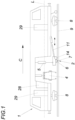
- a stuffing machine 1 ( Fig. 1 ) has a tamping unit 4 and a lifting-straightening device 2 with a lifting cylinder 5, with a roller clamp with lifting roller 6 and with a lifting hook 7.
- the lifting and straightening device can be moved in the longitudinal direction of the track using a hydraulic cylinder 11.
- the switch tamping machine can be moved on the track using running gear 8.
- the tamping machine 1 is controlled from the work cabin 28 arranged in front of the tamping unit 4 in the working direction C.
- the work cabin 28 and the driving cabins can be entered via side doors 29.
- a known (SdT) design of a lifting and straightening device 2 shows the rolling tongs 6, the rolling tongs locking cylinder 12, the lifting cylinder 5 with the lifting force FH, the rail 9 and the guide straightening wheel 14.
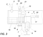
- FIG. 3 A state-of-the-art embodiment of the lifting and straightening device 2 is shown Fig. 3 in particular the common support bracket 10, the vertical guide cylinders of the lifting roller 3 and the lifting hook 13 with lifting movement V with lifting path sensors 20, 21, the common transverse guide 16, the displacement cylinder 17 with displacement path H and displacement path sensor 22, the guide straightening wheel 14, the lifting roller 6, the lifting hook 7 in the closed position at the rail head and in the closed position at the rail foot 19, the rail 9, the lifting cylinder 5 with the lifting force FH.
- FIG. 4 shows the roller clamp with lifting roller 6, whereby the transverse displacement path H of the transverse guide 16 and the swivel range of the swivel drive 12 are extended in such a way that a rail 9 with the lifting roller 6 can be grasped from both the outside and the inside of the track. If the guide carriage 10 with the bracket 31 is displaced sufficiently, the lifting roller 33 can also grip the inside of the rail at the rail head. A straightening wheel 14 guides the lifting-straightening device on the rail 9.
- Fig. 5 shows a very simplified roller clamp once in closed and once in open state 15.
- a horizontally positioned roller clamp 23 would be required.
- Conflicts 25 If this horizontal roller clamp 23 remained during the right of way, it would damage the fastening means 26.
- FIG. 6 shows the lifting and straightening device 2 of a tamping machine according to the invention.
- the lifting and straightening device 2 for lifting and straightening tracks and switches of the tamping machine for compacting the ballast bed of a track is equipped with at least one height-adjustable lifting roller 6 and with at least one independently height-adjustable lifting hook 7, wherein the lifting roller 6 and the lifting hook 7 are arranged on a common bracket 31, which is guided by an actuator 17 so as to be displaceable transversely to the longitudinal axis L of the tamping machine.
- the bracket 31 is arranged on a guide carriage 10, with which it can be displaced transversely to the longitudinal axis L of the tamping machine along a transverse guide 16.
- the bracket 31 is mounted on the guide carriage 10 with a pivot drive (12), here a hydraulic cylinder, so as to be pivotable about a pivot axis 30 parallel to the longitudinal axis of the tamping machine.
- the actuator 17 is a transverse displacement cylinder with a displacement sensor 22, the lifting roller 6 is height-adjustable with a vertical lifting cylinder 3 with a stroke sensor 20 and the lifting hook 7 is height-adjustable with a vertical lifting cylinder 13 with a stroke sensor 21.
- a stroke sensor 32 is assigned to the swivel drive 12, in this case the swivel cylinder.
- the bracket 31 is mounted with the swivel drive 12 on the guide carriage 10 so that it can pivot about the swivel axis 30 parallel to the longitudinal axis of the tamping machine.
- the displacement sensor 22 of the displacement cylinder 17, the stroke sensor 20 of the vertical lifting cylinder 3 for the lifting roller 6 and the stroke sensor 21 of the vertical lifting cylinder 13 for the lifting hook 7 and the stroke sensor 32 for the swivel cylinder 12 are each integrated in the associated cylinder.
Landscapes
- Engineering & Computer Science (AREA)
- Architecture (AREA)
- Civil Engineering (AREA)
- Structural Engineering (AREA)
- Machines For Laying And Maintaining Railways (AREA)
Description
- Die Erfindung bezieht sich auf eine Stopfmaschine zum Verdichten der Schotterbettung eines Gleises, mit Stopfaggregaten zum Unterstopfen eines Gleises, mit einer zwischen Laufwerken, in Arbeitsrichtung vorzugsweise vor den Stopfaggregaten, angeordneten Hebe-Richteinrichtung zum Heben und Richten von Gleisen und Weichen, mit wenigstens einer höhenverstellbaren Heberolle und mit wenigstens einem unabhängig davon höhenverstellbaren Hebehaken, wobei die Heberolle und der Hebehaken an einer gemeinsamen Konsole angeordnet sind, die mit einem Stelltrieb quer zur Stopfmaschinenlängsachse verschiebbar geführt ist.
- Weichenstopfmaschinen sind Maschinen zur Berichtigung der Gleislage von Weichen und Gleisen. Zur Feststellung der Gleislage werden Messsysteme eingesetzt welche die Gleishöhen-Istlage, die Gleisrichtungs-Istlage sowie die Überhöhungs-Istlage des Gleises während der Arbeit messen und mit vorgegebenen Sollwerten abgleichen. Mit Hilfe eines Gleishebe-, Gleisrichtaggregates wird der Gleisrost angehoben und seitlich ausgerichtet bis die Differenz zwischen vorgegebener Soll-Lage und Ist-Lage Null ist. In dieser räumlichen Lage wird die Weiche durch Verdichten des Schotters unter den Schwellen mit Hilfe eines Stopfaggregates festgelegt. Das Heben und Richten des Gleisrostes erfolgt über hydraulische Hebe- und Richtzylinder mit Proportional- oder Servosteuerung. Weichen weisen als Besonderheit ein durchgehendes Gleis und ein abzweigendes Gleis auf. Züge werden über so genannte Zungen in den Abzweig geleitet oder auf dem durchgehenden Hauptgleis gehalten. Im Kreuzungspunkt des durchgehenden Gleisstranges und des abzweigenden Stranges liegt das so genannte Herzstück. Im Bereich des Herzstücks muss das Eisenbahnrad von der Schiene des durchgehenden Stranges auf die Schiene des abzweigenden Stranges geführt werden. Damit das im Unterbrechungsbereich nicht geführte Rad sicher in den Abzweig oder in den durchgehenden Hauptstrang rollt sind Führungsschienen vorgesehen. Um Sicherzustellen, dass die Arbeitswerkzeuge der Weichenstopfmaschine die Weichenschwellen an allen Stellen unterstopfen können sind die Stopfaggregate seitlich verschiebbar und wegen der schrägliegenden Langschwellen sind die Stopfaggregate drehbar. Die Stopfpickel können zusätzlich zumindest zum Teil schwenkbar ausgeführt sein.
- Bei reinen Streckenstopfmaschinen wird die Schiene am Kopf mit Rollzangen erfasst und in die geometrische Soll-Lage gehoben. In Weichen ist eine Anwendung der Rollzange wegen der sich kreuzenden Schienen und im Herzstück oft nicht möglich. Damit auch diese Stellen bearbeitbar (einrichtbar) sind werden zusätzlich seitlich ausfahrbare und in der Tiefe höhenverstellbare verstellbare Hebehaken oder Heberollen vorgesehen (
WO2016191776A1 ). In derDE 3738750 A1 geoffenbarte Hebehaken und Heberollen einer Stopfmaschine sind voneinander unabhängig um jeweilige Schwenkachsen verlagerbar. - Von der Kabine aus steuert der Maschinenführer die Position des Stopfaggregates und er wählt je nach den Verhältnissen und Gutdünken die Rollenzange oder den Hebehaken bzw. die Position des Hebehakens sowie den Angriffspunkt desselben am Schienenkopf oder am Schienenfuß. Die Hebeeinrichtung kann auch in Gleislängsrichtung verschoben werden. Dies ist dann notwendig, wenn der Hebehaken am Schienenfuß angreift - dies ist nur im Bereich des Zwischenfaches möglich - oder wenn durch einen Isolierstoß z.B. die Rollzange oder der Hebehaken nicht am Schienenkopf angreifen können.
- Die übliche gelenkige Anordnung der Rollzange die drehend geschlossen wird hat den Nachteil, dass oftmals durch die Hebekräfte die Zange aufgezwängt wird und ausreißt. Ein weiterer Nachteil dieser Ausführung der um einen Drehpunkt schließenden Rollzange ist, dass die Rolle bei entsprechendem Verschleiß oder bei unterschiedlichen Schienenkopfhöhen manuell nachgestellt werden muss und dass die Rollenzange in ihrer Position quer zum Gleis fixiert ist. Wird die Höhe der Rollenzange nicht an die Verhältnisse angepasst, dann hebt um das vorhandene Spiel die Richtrolle von der Schiene ab. Dies führt zu einer nicht erwünschten Beanspruchung des Schienenkopfes weiter oberhalb und führt leicht zu einem Abrutschen der Richtrolle mit nachfolgendem Entgleisen. Ein weiterer Nachteil ist, dass drehbare Rollenzangen oftmals wegen der räumlichen Verhältnisse so in das Hebe-Richtaggregat integriert werden müssen, dass die Zugänglichkeit erschwert ist. Dies erhöht den Zeitaufwand für Wartungsarbeiten bzw. Reparaturarbeiten. Ein Nachstellen der Rolle in Höhenrichtung erfordert entsprechend großen Zeit- und Kostenaufwand.
- Zusätzlich ergibt sich auf Grund der unterschiedlichen Arbeitsweise der Rollenzange und des Hebehakens eine abweichende Bedienung der Befehlsgeräte durch den Bediener.
- Gemäß der
WO2016191776A1 können Heberolle und Hebehaken vertikal und horizontal, also quer zur Stopfmaschinenlängsachse, geführt werden. Hebehaken und Heberolle sind an einer gemeinsamen Konsole angeordnet und können mit der Konsole entlang einer Querführung gemeinsam verlagert werden. Die Heberolle wird wie der Hebehaken hydraulisch mittels Zylindern vertikal geführt abgesenkt bzw. gehoben. Die Konsole wird zum Greifen eines Schienenkopfes mit der Heberolle bzw. zum Greifen der Schiene mit dem Hebehaken horizontal nach innen zur Gleismitte hin gefahren. Anschließend wird die Heberolle nach oben gefahren bis sie an der Schienenkopfunterseite anliegt. Dadurch wird die Abhängigkeit vom Verschleiß der Rolle oder unterschiedlichen Schienenkopfhöhen vermieden. Ein Nachstellen der Rolle ist nicht mehr notwendig. Die Bedienung erfolgt durch die erfindungsgemäße Ausführung vom Ablauf her wie jene beim Hebehaken. Durch den Formschluss zwischen Heberolle, Schienenkopf und Richtrolle wird ein Aufzwängen und Ausreißen der Heberolle vermieden. Bei einer aus derCH 705271 A2 - Der Nachteil dieser Ausführung ist, dass Heberolle und Hebehaken nur vertikal und horizontal bewegt werden können. Beim Stopfen von Streckengleisen kommt es auf die Geschwindigkeit an. Bleibt die so geführte Rolle beim schnellen Vorwärtsfahren an der Schiene anliegend, dann fährt sie unter Umständen an hochstehenden Schienenbefestigungsmitteln, Isolierstößen oder Schienenschweißwülsten an. Durch die reine Horizontalführung der Rolle kann diese nicht so schnell aufgezwängt werden, wodurch es zu Beschädigungen an der Rolle, dem Hebe-Richt-Aggregat oder an den Schienenbefestigungen kommen kann. Daher wird die Rolle vor der Vorfahrt bei hochstehenden Kleineisen seitlich weit genug ausgefahren um eine Beschädigung zu vermeiden und nach dem Stillstehen der Maschine wieder eingefahren. Das kostet Zeit. Gibt es mit den Kleineisen keinen Konflikt, weil diese niedrig ausgeführt sind, dann wird die Rollzange vor der Vorfahrt nur bis zur Schienenkopfbreite ausgefahren und dann beim Stillstand wieder geschlossen. Auch das kostet Zeit, was vor allem beim Streckengleisstopfen nachteilig auf die Maschinenleistung auswirkt. Ein weiterer Nachteil ist, dass um den Stellweg zu verringern gegebenenfalls der Hebekranz der Heberolle mit verringerter Stärke ausgeführt wird. Dadurch neigt der Hebekranz zum Bruch.
- Der Erfindung liegt somit die Aufgabe zugrunde, eine Ausführung der Hebe-Richteinrichtung zu finden, bei welcher beim schnellen Vorwärtsfahren die Heberolle derart rasch ausweichen kann, dass Beschädigungen an der Rolle, der Hebe-Richteinrichtung oder den Schienenbefestigungen vermieden werden.
- Die Erfindung löst die gestellte Aufgabe dadurch, dass die Konsole auf einem Führungsschlitten angeordnet ist, mit dem sie quer zur Stopfmaschinenlängsachse entlang einer Querführung verschiebbar ist und dass die Konsole mit einem Schwenktrieb um eine stopfmaschinenlängsachsenparallele Schwenkachse schwenkverstellbar am Führungsschlitten gelagert ist. Vorteilhafte Weiterbildungen der Erfindung sind in den Unteransprüchen dargestellt.
- Hebehaken und Heberolle sind an der gemeinsamen Konsole gelagert und je für sich mit einem Hubtrieb höhenverstellbar. Erfindungswesentlich ist, dass diese Konsole bezüglich des Führungsschlittens drehbar ausgeführt wird, also um eine stopfmaschinenlängsachsenparallele Schwenkachse schwenkverstellbar ist. Damit bleiben die Vorteile der vertikalen und horizontalen Positionierbarkeit von Heberolle und Hebehaken erhalten. Damit kann diese perfekt in Weichen eingesetzt werden. Für das schnelle Streckenstopfen wird der Antrieb zur Drehbewegung der Hebewerkzeugkonsole floatend oder mit geringer Kraft anpressend betrieben. Bei einem Schienenstoß bzw. bei auftretenden Schweißwülsten wird die Heberolle einfach aufgezwängt. Durch die Schrägstellung der Rolle, gibt es auch keinen Konflikt mit den Schienenbefestigungen. Ein weiterer Vorteil ist, dass der Hebekranz der Heberolle auf Grund der Verschwenkbarkeit stärker ausgeführt werden kann und daher nicht mehr zum Bruch neigt.
- Die Führungsschlitten ist entlang der Querführung quer zur Stopfmaschinenlängsachse verfahrbar. Auf der Konsole, die insbesondere um die Stopfmaschinenlängsachse schwenkverstellbar am Führungsschlitten gelagert ist, stützen sich die Kolbenstangen bzw. Zylinder von zwei Hydraulikzylindern ab. Ein Hydraulikzylinder mit kleinerem Hub dient zur Vertikaleinstellung der Heberolle. Der andere Hydraulikzylinder mit längerem Hub ist für den Hebehaken vorgesehen. Der längere Hub ist notwendig damit der Hebehaken sowohl am Schienenkopf, als auch am Schienenfuß angreifen kann. Die Hydraulikzylinder sind mit dem Hebehaken bzw. mit der Heberolle verbunden die ihrerseits entlang von Vertikalführungen (in der Konsole) auf und ab bewegt werden können. Der Führungsschlitten mit der Konsole mit der Heberolle bzw. dem Hebehaken werden über einen quer zur Stopfmaschinenlängsachse liegenden und sich an der Hebe-Richteinrichtung abstützenden Hydraulikzylinder in die jeweilige Position (Angriff Heberolle oder Hebehaken) gebracht. Die Konsole kann über den Schwenktrieb verschwenkt werden. Damit kann die Heberolle bei Vorfahrt eingeschwenkt und/oder mit verringertem Druck als Überlastsicherung zur Schwenkkraftbeschränkung geschlossen bleiben. Tritt ein Hindernis auf, dann kann die Heberolle vom Hindernis beim Überschreiten des eingestellten Schließdruckes leicht aufgedrückt werden. Bei Arbeiten in Weichen kann die aus einer vertikalen Nullage nicht verschwenkte, rein vertikale Position oder eine entsprechend günstigere verschwenkte Konsolenstellung gewählt werden. Damit kann der Haken oder die Rolle platzsparend vertikal von oben zugestellt werden. Dann wird das Hebewerkzeug mit der Verschiebekonsole nach innen verschoben bis das Hebewerkzeug Kontakt mit der Schiene hat. Im anschließenden Vorgang wird es angehoben bis sich der Formschluss zwischen Hebewerkzeug und Schiene einstellt.
- Wird die Hebe-Richteinrichtung nun mit der Hebekraft beaufschlagt kann die Richtrolle nicht vom Gleis abheben da ein Formschluss zwischen Hebewerkzeug und Schiene vorliegt.
- Eine vorteilhafte Ausführung der Erfindung ergibt sich, wenn der Stelltrieb ein Querverschiebezylinder mit einem Verschiebewegsensor ist, wenn die Heberolle mit einem Vertikalhubzylinder mit Hubwegsensor höhenverstellbar und wenn der Hebehaken mit einem Vertikalhubzylinder mit Hubwegsensor höhenverstellbar ist. Zudem können dem Schwenktrieb ein Drehwinkelsensor und/oder einem Schwenkzylinder des Schwenktriebs ein Hubwegsensor zugeordnet sein.
- Mit Hilfe dieser Sensoren kann der gesamte Schließ- und Arbeitsvorgang der Hebewerkzeuge automatisiert werden. Dazu werden die seitlich notwendigen Verschiebungen, die vertikalen Hubwerte und die Verdreheinstellung als Sollwerte vorgegeben und mit den gemessenen Istwerten verglichen. Dadurch wird der Bediener weiter entlastet. Sind der Verschiebewegsensor des Verschiebezylinders, der Hubwegsensor des Vertikalhubzylinders für die Heberolle und der Hubwegsensor des Vertikalhubzylinders für den Hebehaken und der Hubwegsensor für den Schwenkzylinder je in den zugeordneten Zylinder integriert, dann ergibt sich eine besonders robuste, wenig störanfällige und aufgeräumte Konstruktion.
- Über die an der Schiene anliegende Heberolle ist ein eindeutiger Bezug zur Schiene gegeben. Da die Heberolle mit der Hebe-Richteinrichtung verbunden ist, ist damit auch ein eindeutiger Bezug zu den Bewegungen der Hebewerkzeuge in Bezug auf die Schiene gegeben.
- Ein weiterer Vorteil der erfindungsgemäßen Ausführung mit Weggebern ist, dass das eindeutige Schließen der Hebewerkzeuge und der damit verbundene Formschluss gemessen und überwacht werden können.
- Können der Hebehaken oder die Heberolle z.B. nicht unter den Schienenkopf gebracht werden, weil ein Isolier- oder Schweißstoß das Schließen mechanisch verhindert, so kann dies über den entsprechenden nicht ausreichenden Schließweg gemessen werden. In diesem Fall kann z.B. automatisch der Hebehaken tiefer abgesenkt werden, um am Schienenfuß zu greifen. Eine andere Möglichkeit ist die Hebe-Richteinrichtung in Längsrichtung parallel zum Gleis zu verfahren bis die Heberolle oder der Hebehaken wieder eindeutig greifen können. Erfindungsgemäß ergibt sich durch die Verwendung einer gemeinsamen Konsole und einer gemeinsamen Verwendung der Querführung und des Schwenktriebes für die Heberolle und den Hebehaken eine Vereinfachung des Systems, die mit gleichbleibenden Bedienungsschritten einhergeht und die automatisiert werden kann.
- Durch die Möglichkeiten des Einschwenkens der Heberolle kann diese erfindungsgemäß beim Streckenstopfen geschlossen bleiben und an der Schiene anliegen. Dadurch verringert sich die Aktivierungszeit der Heberolle und die Arbeitsgeschwindigkeit der Stopfmaschine steigt. Außerdem werden mögliche Beschädigungen vermieden.
- Durch die erfindungsgemäße Ausführung sind die Hebevorrichtungen gut zugänglich und erleichtern die Wartung und Reparatur. Das Verschwenken der Hebewerkzeuge erleichtert die Inspektion der Hebewerkzeuge.
- Da die Heberolle bei der erfindungsgemäßen Ausführung durch horizontale, vertikale und drehende Bewegungen in einen Formschluss mit dem Schienenkopf gebracht wird und dies unabhängig von der Größe der Abnutzung der Heberolle oder der Höhe des Schienenkopfes geschieht, entfällt die Notwendigkeit einer höhenmäßigen Nachstellung der Heberolle.
- In der Zeichnung ist der Erfindungsgegenstand beispielsweise dargestellt. Es zeigen
-
Fig. 1 eine gleisfahrbare Gleisstopfmaschine in Seitenansicht, -
Fig. 2 eine Rollenzange gemäß des Standes der Technik in Ansicht, -
Fig. 3 eine Hebe-Richteinrichtung gem. des Standes der Technik in Ansicht, -
Fig. 4 eine beiderseits der Schiene angreifende Heberolle, -
Fig. 5 eine stark vereinfachte verschwenkbare Heberolle zur Darstellung der Eingriffssituation an einem Schienenkopf und -
Fig. 6 eine erfindungsgemäß mit Heberolle mit Hebehaken schwenkverstellbare Konsole in Ansicht. - Eine Stopfmaschine 1 (
Fig. 1 ) weist ein Stopfaggregat 4 und eine Hebe-Richteinrichtung 2 mit einem Hebezylinder 5, mit einer Rollzange mit Heberolle 6 und mit einem Hebehaken 7 auf. Die Hebe-Richteinrichtung kann über einen Hydraulikzylinder 11 in Gleislängsrichtung verschoben werden. Die Weichenstopfmaschine ist über Laufwerke 8 auf dem Gleis verfahrbar. Die Steuerung der Stopfmaschine 1 erfolgt von der in Arbeitsrichtung C vor dem Stopfaggregat 4 angeordneten Arbeitskabine 28 aus. Über seitliche Türen 29 können die Arbeitskabine 28 und die Fahrkabinen betreten werden. - Die Ansicht gemäß
Fig. 2 einer bekannten (SdT) Ausführung einer Hebe-Richteinrichtung 2 zeigt die Rollzange 6, den Rollzangenschließzylinder 12, den Hebezylinder 5 mit der Hebekraft FH, die Schiene 9 und das Führungs-Richtrad 14. - Eine Ausführung gemäß des Standes der Technik des der Hebe-Richteinrichtung 2 zeigt
Fig. 3 insbesondere die gemeinsame Abstützkonsole 10, die Vertikalführungszylinder der Heberolle 3 und des Hebehakens 13 mit Hubbewegung V mit Hubwegsensoren 20, 21, die gemeinsame Querführung 16, den Verschiebezylinder 17 mit Verschiebeweg H und Verschiebewegsensor 22, das Führungs-Richtrad 14, die Heberolle 6, den Hebehaken 7 in am Schienenkopf geschlossener Stellung und in am Schienenfuß geschlossener Stellung 19, die Schiene 9, den Hebezylinder 5 mit der Hebekraft FH. - Die Ansicht gemäß
Fig. 4 zeigt die Rollenzange mit Heberolle 6, wobei der Querverschiebeweg H der Querführung 16 und der Schwenkbereich des Schwenktriebs 12 derart erweitert sind, dass eine Schiene 9 mit der Heberolle 6 sowohl von der Gleisaußenseite, als auch von der Gleisinnenseite her greifbar ist. Bei hinreichend großem Verschub des Führungsschlittens 10 mit der Konsole 31 kann die Heberolle 33 auch innen an der Schiene am Schienenkopf angreifen. Ein Richtrad 14 führt die Hebe-Richt-Einrichtung auf der Schiene 9. -
Fig. 5 zeigt eine stark vereinfachte Rollenzange einmal in geschlossenem und einmal in geöffneten Zustand 15. Bei Ausführungen der Schienenbefestigungen (26) die sehr hoch bauen würde eine horizontal zugestellte Rollenzange 23 zu Konflikten 25 führen. Bliebe diese horizontal beigestellte Rollenzange 23 während der Vorfahrt geschlossen, dann würde sie die Befestigungsmittel 26 beschädigen. - Tritt ein Isolierstoß 24 auf dann würde die geschlossene Rollenzange 23 plötzlich ruckartig aufgedrückt, was zu hohen Kräften und Beschädigungen führen würde.
Fig. 6 zeigt die Hebe-Richteinrichtung 2 einer erfindungsgenmäßen Stopfmaschine. - Die Hebe-Richteinrichtung 2 zum Heben und Richten von Gleisen und Weichen der Stopfmaschine zum Verdichten der Schotterbettung eines Gleises ist mit wenigstens einer höhenverstellbaren Heberolle 6 und mit wenigstens einem unabhängig davon höhenverstellbaren Hebehaken 7 ausgestattet, wobei die Heberolle 6 und der Hebehaken 7 an einer gemeinsamen Konsole 31 angeordnet sind, die mit einem Stelltrieb 17 quer zur Stopfmaschinenlängsachse L verschiebbar geführt ist. Die Konsole 31 ist auf einem Führungsschlitten 10 angeordnet, mit dem sie quer zur Stopfmaschinenlängsachse L entlang einer Querführung 16 verschiebbar ist. Zudem ist die Konsole 31 mit einem Schwenktrieb (12), hier einem Hydraulikzylinder, um eine stopfmaschinenlängsachsenparallele Schwenkachse 30 schwenkverstellbar am Führungsschlitten 10 gelagert ist.
- Der Stelltrieb 17 ist ein Querverschiebezylinder mit einem Verschiebewegsensor 22, die Heberolle 6 ist mit einem Vertikalhubzylinder 3 mit Hubwegsensor 20 höhenverstellbar und der Hebehaken 7 ist mit einem Vertikalhubzylinder 13 mit Hubwegsensor 21 höhenverstellbar. Dem Schwenktrieb 12, hier also dem Schwenkzylinder ist ein Hubwegsensor 32 zugeordnet.
- Die Konsole 31 ist mit dem Schwenktrieb 12 am Führungsschlitten 10 um die stopfmaschinenlängsachsenparallele Schwenkachse 30 schwenkverstellbar gelagert.
- Der Verschiebewegsensor 22 des Verschiebezylinders 17, der Hubwegsensor 20 des Vertikalhubzylinders 3 für die Heberolle 6 und der Hubwegsensor 21 des Vertikalhubzylinders 13 für den Hebehaken 7 und der Hubwegsensor 32 für den Schwenkzylinder 12 sind je in den zugeordneten Zylinder integriert.
Claims (6)
- Stopfmaschine (1) zum Verdichten der Schotterbettung eines Gleises, mit Stopfaggregaten (4) zum Unterstopfen eines Gleises, mit einer zwischen Laufwerken (8), in Arbeitsrichtung (C) vorzugsweise vor den Stopfaggregaten (4), angeordneten Hebe-Richteinrichtung (2) zum Heben und Richten von Gleisen und Weichen, mit wenigstens einer höhenverstellbaren Heberolle (6) und mit wenigstens einem unabhängig davon höhenverstellbaren Hebehaken (7), wobei die Heberolle (6) und der Hebehaken (7) an einer gemeinsamen Konsole (31) angeordnet sind, die mit einem Stelltrieb (17) quer zur Stopfmaschinenlängsachse (L) verschiebbar geführt ist, dadurch gekennzeichnet, dass die Konsole (31) auf einem Führungsschlitten (10) angeordnet ist, mit dem sie quer zur Stopfmaschinenlängsachse (L) entlang einer Querführung (16) verschiebbar ist und dass die Konsole (31) mit einem Schwenktrieb (12) um eine stopfmaschinenlängsachsenparallele Schwenkachse (30) schwenkverstellbar am Führungsschlitten (10) gelagert ist.
- Stopfmaschine nach Anspruch 1, dadurch gekennzeichnet, dass der Stelltrieb (17) ein Querverschiebezylinder mit einem Verschiebewegsensor (22) ist, dass die Heberolle (6) mit einem Vertikalhubzylinder (3) mit Hubwegsensor (20) höhenverstellbar ist und dass der Hebehaken (7) mit einem Vertikalhubzylinder (13) mit Hubwegsensor (21) höhenverstellbar ist.
- Stopfmaschine nach Anspruch 1 oder 2, dadurch gekennzeichnet, dass dem Schwenktrieb (12) ein Drehwinkelsensor und/oder einem Schwenkzylinder des Schwenktriebs (12) ein Hubwegsensor (32) zugeordnet ist.
- Stopfmaschine nach Anspruch 2 oder 3, dadurch gekennzeichnet, dass der Verschiebewegsensor (22) des Verschiebezylinders (17), der Hubwegsensor (20) des Vertikalhubzylinders (3) für die Heberolle (6) und der Hubwegsensor (21) des Vertikalhubzylinders (13) für den Hebehaken (7) und der Hubwegsensor (32) für den Schwenkzylinder (12) je in den zugeordneten Zylinder integriert sind.
- Stopfmaschine nach einem der Ansprüche 1 bis 4, dadurch gekennzeichnet, dass der Querverschiebeweg (H) der Querführung (16) und der Schwenkbereich des Schwenktriebs (12) derart erweitert sind, dass eine Schiene (9) mit der Heberolle (6), und gegebenenfalls mit einem mit T-förmigem Fuß ausgestatteten Hebehaken (7), sowohl von der Gleisaußenseite, als auch von der Gleisinnenseite her greifbar ist.
- Stopfmaschine nach einem der Ansprüche 1 bis 5, dadurch gekennzeichnet, dass dem Schwenktrieb (12) zur Überlastsicherung eine Schwenkkraftbegrenzung zugeordnet ist.
Applications Claiming Priority (2)
| Application Number | Priority Date | Filing Date | Title |
|---|---|---|---|
| ATA50360/2021A AT525020B1 (de) | 2021-05-11 | 2021-05-11 | Stopfmaschine zum Verdichten der Schotterbettung eines Gleises |
| PCT/AT2022/060146 WO2022236349A1 (de) | 2021-05-11 | 2022-04-28 | Stopfmaschine zum verdichten der schotterbettung eines gleises |
Publications (3)
| Publication Number | Publication Date |
|---|---|
| EP4337829A1 EP4337829A1 (de) | 2024-03-20 |
| EP4337829C0 EP4337829C0 (de) | 2024-11-20 |
| EP4337829B1 true EP4337829B1 (de) | 2024-11-20 |
Family
ID=81597966
Family Applications (1)
| Application Number | Title | Priority Date | Filing Date |
|---|---|---|---|
| EP22722397.1A Active EP4337829B1 (de) | 2021-05-11 | 2022-04-28 | Stopfmaschine zum verdichten der schotterbettung eines gleises |
Country Status (6)
| Country | Link |
|---|---|
| US (1) | US20240271370A1 (de) |
| EP (1) | EP4337829B1 (de) |
| JP (1) | JP7820411B2 (de) |
| CN (1) | CN117280094A (de) |
| AT (1) | AT525020B1 (de) |
| WO (1) | WO2022236349A1 (de) |
Families Citing this family (4)
| Publication number | Priority date | Publication date | Assignee | Title |
|---|---|---|---|---|
| AT18508U1 (de) * | 2020-06-08 | 2025-07-15 | Hp3 Real Gmbh | Verfahren zur automatischen autonomen Steuerung einer Stopfmaschine |
| AT524193B1 (de) * | 2020-09-10 | 2024-01-15 | Hp3 Real Gmbh | Gleisstopfmaschine zum Verdichten der Schotterbettung eines Gleises |
| AT17648U1 (de) * | 2021-03-15 | 2022-10-15 | Plasser & Theurer Export Von Bahnbaumaschinen Gmbh | Verfahren zum Reinigen eines Schotterbettes eines Gleises |
| AT18206U1 (de) * | 2022-11-29 | 2024-05-15 | Plasser & Theurer Export Von Bahnbaumaschinen Gmbh | Hebeaggregat für eine Stopfmaschine |
Family Cites Families (20)
| Publication number | Priority date | Publication date | Assignee | Title |
|---|---|---|---|---|
| AT343165B (de) * | 1975-01-31 | 1978-05-10 | Plasser Bahnbaumasch Franz | Fahrbare schotterbett-verdichtmaschine zur korrektur der gleislage |
| AT356165B (de) * | 1978-05-11 | 1980-04-10 | Plasser Bahnbaumasch Franz | Gleisstopfmaschine mit gleishebe- und seiten- richtvorrichtung, insbesondere fuer weichen- bereiche |
| AT369069B (de) * | 1980-09-04 | 1982-12-10 | Plasser Bahnbaumasch Franz | Fahrbare gleisstopf-nivellier-richtmaschine |
| IT1152387B (it) * | 1982-09-10 | 1986-12-31 | Riva Calzoni Spa | Dispositivo di protezione contro sovraccarichi in un cilindro idraulico |
| CH652774A5 (fr) * | 1983-05-19 | 1985-11-29 | Sig Schweiz Industrieges | Machine de chantier ferroviaire dont le chassis roulant est equipe d'un dispositif pour lever et riper une voie ferree. |
| GB2201445B (en) * | 1987-02-27 | 1991-01-02 | Plasser Bahnbaumasch Franz | A travelling track maintenance machine, more especially a tamping, lifting and lining machine for switches and crossings |
| AT388949B (de) * | 1987-02-27 | 1989-09-25 | Plasser Bahnbaumasch Franz | Fahrbare gleisbearbeitungsmaschine fuer den weichen- und kreuzungsbereich |
| AT391903B (de) * | 1989-01-26 | 1990-12-27 | Plasser Bahnbaumasch Franz | Fahrbare gleisbearbeitungsmaschine mit einer einrichtung zur steuerung der arbeits-position ihrer arbeits-aggregate bzw. -werkzeuge |
| SK379392A3 (en) * | 1992-03-25 | 1996-09-04 | Plasser Bahnbaumasch Franz | Track tamping machine |
| ATE139282T1 (de) * | 1992-08-12 | 1996-06-15 | Plasser Bahnbaumasch Franz | Gleisstopfmaschine zum unterstopfen von weichen und kreuzungen eines gleises |
| AT3739U3 (de) * | 2000-04-07 | 2001-03-26 | Plasser Bahnbaumasch Franz | Stopfmaschine |
| AT508755B1 (de) * | 2010-03-01 | 2011-04-15 | Plasser Bahnbaumasch Franz | Stopfmaschine mit einer zusatzhebeeinrichtung |
| CH705271A2 (fr) * | 2011-07-15 | 2013-01-15 | Dreco Sa | Pince de nivellement-dressage combinée pour bourreuses-niveleuses-dresseuses de voies ferrées. |
| CN103132406B (zh) * | 2011-11-24 | 2015-06-03 | 金鹰重型工程机械有限公司 | 米轨起拨道装置 |
| AT516358B1 (de) * | 2014-10-14 | 2017-01-15 | System 7 - Railsupport GmbH | Stopfmaschine zum Verdichten der Schotterbettung eines Gleises |
| AT516827B1 (de) * | 2015-06-02 | 2016-09-15 | System 7 - Railsupport GmbH | Stopfmaschine zum Verdichten der Schotterbettung eines Gleises |
| AT521262B1 (de) * | 2018-07-05 | 2019-12-15 | Hp3 Real Gmbh | Stopfmaschine zum Verdichten der Schotterbettung eines Gleises |
| CN111979856A (zh) * | 2019-05-21 | 2020-11-24 | 中国铁建高新装备股份有限公司 | 一种起拨道装置及起拨道作业方法 |
| CN210797128U (zh) * | 2019-06-21 | 2020-06-19 | 中国铁建高新装备股份有限公司 | 一种适用于道岔作业的捣固车 |
| AT17436U1 (de) * | 2020-12-02 | 2022-04-15 | Hp3 Real Gmbh | Verfahren zur automatischen autonomen Steuerung einer Stopfmaschine |
-
2021
- 2021-05-11 AT ATA50360/2021A patent/AT525020B1/de active
-
2022
- 2022-04-28 US US18/289,879 patent/US20240271370A1/en active Pending
- 2022-04-28 WO PCT/AT2022/060146 patent/WO2022236349A1/de not_active Ceased
- 2022-04-28 CN CN202280033873.5A patent/CN117280094A/zh active Pending
- 2022-04-28 JP JP2023569842A patent/JP7820411B2/ja active Active
- 2022-04-28 EP EP22722397.1A patent/EP4337829B1/de active Active
Also Published As
| Publication number | Publication date |
|---|---|
| AT525020A1 (de) | 2022-11-15 |
| AT525020B1 (de) | 2023-01-15 |
| WO2022236349A1 (de) | 2022-11-17 |
| US20240271370A1 (en) | 2024-08-15 |
| EP4337829C0 (de) | 2024-11-20 |
| JP7820411B2 (ja) | 2026-02-25 |
| CN117280094A (zh) | 2023-12-22 |
| JP2024517933A (ja) | 2024-04-23 |
| EP4337829A1 (de) | 2024-03-20 |
Similar Documents
| Publication | Publication Date | Title |
|---|---|---|
| EP4337829B1 (de) | Stopfmaschine zum verdichten der schotterbettung eines gleises | |
| EP3303703B1 (de) | Stopfmaschine zum verdichten der schotterbettung eines gleises | |
| AT516590B1 (de) | Verfahren und Vorrichtung zum Verdichten der Schotterbettung eines Gleises | |
| AT516311B1 (de) | Gleisstopfmaschine zum Verdichten der Schotterbettung eines Gleises | |
| DE3347860C2 (de) | ||
| DE3904179C2 (de) | Fahrbare Gleisstopf-, Hebe- und Richtmaschine zum Heben und/oder Seitwärtsverschieben eines Gleises im Weichen- und Kreuzungsbereich | |
| EP0584055B1 (de) | Gleisstopfmaschine zum Unterstopfen von Weichen und Kreuzungen eines Gleises | |
| DE2928474A1 (de) | Fahrbare gleisbearbeitungsmaschine fuer weichen, kreuzungen und streckengleise | |
| DE3886418T2 (de) | Schienenschleifvorrichtung. | |
| DE3110832C2 (de) | Fahrbare Gleisbaumaschine mit einer Gleislage-Korrekturvorrichtung | |
| EP2542719B1 (de) | Stopfmaschine mit einer zusatzhebeeinrichtung | |
| EP3009564B1 (de) | Stopfmaschine zum verdichten der schotterbettung eines gleises | |
| AT508152B1 (de) | Maschine mit einer aushubeinrichtung zur aufnahme von schüttgut einer gleisbettung | |
| DE1261819B (de) | Geruestueberbau fuer haengende Aufnahme von Walzgeruesten | |
| DE20208677U1 (de) | Lastaufnahmemittel, insbesondere für Schienengleise |
Legal Events
| Date | Code | Title | Description |
|---|---|---|---|
| STAA | Information on the status of an ep patent application or granted ep patent |
Free format text: STATUS: UNKNOWN |
|
| STAA | Information on the status of an ep patent application or granted ep patent |
Free format text: STATUS: THE INTERNATIONAL PUBLICATION HAS BEEN MADE |
|
| PUAI | Public reference made under article 153(3) epc to a published international application that has entered the european phase |
Free format text: ORIGINAL CODE: 0009012 |
|
| STAA | Information on the status of an ep patent application or granted ep patent |
Free format text: STATUS: REQUEST FOR EXAMINATION WAS MADE |
|
| 17P | Request for examination filed |
Effective date: 20231018 |
|
| AK | Designated contracting states |
Kind code of ref document: A1 Designated state(s): AL AT BE BG CH CY CZ DE DK EE ES FI FR GB GR HR HU IE IS IT LI LT LU LV MC MK MT NL NO PL PT RO RS SE SI SK SM TR |
|
| DAV | Request for validation of the european patent (deleted) | ||
| DAX | Request for extension of the european patent (deleted) | ||
| GRAP | Despatch of communication of intention to grant a patent |
Free format text: ORIGINAL CODE: EPIDOSNIGR1 |
|
| STAA | Information on the status of an ep patent application or granted ep patent |
Free format text: STATUS: GRANT OF PATENT IS INTENDED |
|
| INTG | Intention to grant announced |
Effective date: 20240820 |
|
| GRAS | Grant fee paid |
Free format text: ORIGINAL CODE: EPIDOSNIGR3 |
|
| GRAA | (expected) grant |
Free format text: ORIGINAL CODE: 0009210 |
|
| STAA | Information on the status of an ep patent application or granted ep patent |
Free format text: STATUS: THE PATENT HAS BEEN GRANTED |
|
| AK | Designated contracting states |
Kind code of ref document: B1 Designated state(s): AL AT BE BG CH CY CZ DE DK EE ES FI FR GB GR HR HU IE IS IT LI LT LU LV MC MK MT NL NO PL PT RO RS SE SI SK SM TR |
|
| REG | Reference to a national code |
Ref country code: GB Ref legal event code: FG4D Free format text: NOT ENGLISH |
|
| REG | Reference to a national code |
Ref country code: CH Ref legal event code: EP |
|
| REG | Reference to a national code |
Ref country code: DE Ref legal event code: R096 Ref document number: 502022002185 Country of ref document: DE |
|
| REG | Reference to a national code |
Ref country code: IE Ref legal event code: FG4D Free format text: LANGUAGE OF EP DOCUMENT: GERMAN |
|
| U01 | Request for unitary effect filed |
Effective date: 20241213 |
|
| U07 | Unitary effect registered |
Designated state(s): AT BE BG DE DK EE FI FR IT LT LU LV MT NL PT RO SE SI Effective date: 20241223 |
|
| PG25 | Lapsed in a contracting state [announced via postgrant information from national office to epo] |
Ref country code: IS Free format text: LAPSE BECAUSE OF FAILURE TO SUBMIT A TRANSLATION OF THE DESCRIPTION OR TO PAY THE FEE WITHIN THE PRESCRIBED TIME-LIMIT Effective date: 20250320 Ref country code: HR Free format text: LAPSE BECAUSE OF FAILURE TO SUBMIT A TRANSLATION OF THE DESCRIPTION OR TO PAY THE FEE WITHIN THE PRESCRIBED TIME-LIMIT Effective date: 20241120 |
|
| PG25 | Lapsed in a contracting state [announced via postgrant information from national office to epo] |
Ref country code: ES Free format text: LAPSE BECAUSE OF FAILURE TO SUBMIT A TRANSLATION OF THE DESCRIPTION OR TO PAY THE FEE WITHIN THE PRESCRIBED TIME-LIMIT Effective date: 20241120 |
|
| PG25 | Lapsed in a contracting state [announced via postgrant information from national office to epo] |
Ref country code: NO Free format text: LAPSE BECAUSE OF FAILURE TO SUBMIT A TRANSLATION OF THE DESCRIPTION OR TO PAY THE FEE WITHIN THE PRESCRIBED TIME-LIMIT Effective date: 20250220 |
|
| PG25 | Lapsed in a contracting state [announced via postgrant information from national office to epo] |
Ref country code: GR Free format text: LAPSE BECAUSE OF FAILURE TO SUBMIT A TRANSLATION OF THE DESCRIPTION OR TO PAY THE FEE WITHIN THE PRESCRIBED TIME-LIMIT Effective date: 20250221 |
|
| PG25 | Lapsed in a contracting state [announced via postgrant information from national office to epo] |
Ref country code: PL Free format text: LAPSE BECAUSE OF FAILURE TO SUBMIT A TRANSLATION OF THE DESCRIPTION OR TO PAY THE FEE WITHIN THE PRESCRIBED TIME-LIMIT Effective date: 20241120 |
|
| PG25 | Lapsed in a contracting state [announced via postgrant information from national office to epo] |
Ref country code: RS Free format text: LAPSE BECAUSE OF FAILURE TO SUBMIT A TRANSLATION OF THE DESCRIPTION OR TO PAY THE FEE WITHIN THE PRESCRIBED TIME-LIMIT Effective date: 20250220 |
|
| U20 | Renewal fee for the european patent with unitary effect paid |
Year of fee payment: 4 Effective date: 20250425 |
|
| PG25 | Lapsed in a contracting state [announced via postgrant information from national office to epo] |
Ref country code: SM Free format text: LAPSE BECAUSE OF FAILURE TO SUBMIT A TRANSLATION OF THE DESCRIPTION OR TO PAY THE FEE WITHIN THE PRESCRIBED TIME-LIMIT Effective date: 20241120 |
|
| PG25 | Lapsed in a contracting state [announced via postgrant information from national office to epo] |
Ref country code: SK Free format text: LAPSE BECAUSE OF FAILURE TO SUBMIT A TRANSLATION OF THE DESCRIPTION OR TO PAY THE FEE WITHIN THE PRESCRIBED TIME-LIMIT Effective date: 20241120 |
|
| PG25 | Lapsed in a contracting state [announced via postgrant information from national office to epo] |
Ref country code: CZ Free format text: LAPSE BECAUSE OF FAILURE TO SUBMIT A TRANSLATION OF THE DESCRIPTION OR TO PAY THE FEE WITHIN THE PRESCRIBED TIME-LIMIT Effective date: 20241120 |
|
| PLBE | No opposition filed within time limit |
Free format text: ORIGINAL CODE: 0009261 |
|
| STAA | Information on the status of an ep patent application or granted ep patent |
Free format text: STATUS: NO OPPOSITION FILED WITHIN TIME LIMIT |
|
| 26N | No opposition filed |
Effective date: 20250821 |
|
| REG | Reference to a national code |
Ref country code: CH Ref legal event code: H13 Free format text: ST27 STATUS EVENT CODE: U-0-0-H10-H13 (AS PROVIDED BY THE NATIONAL OFFICE) Effective date: 20251125 |
|
| PG25 | Lapsed in a contracting state [announced via postgrant information from national office to epo] |
Ref country code: MC Free format text: LAPSE BECAUSE OF FAILURE TO SUBMIT A TRANSLATION OF THE DESCRIPTION OR TO PAY THE FEE WITHIN THE PRESCRIBED TIME-LIMIT Effective date: 20241120 |
|
| PG25 | Lapsed in a contracting state [announced via postgrant information from national office to epo] |
Ref country code: CH Free format text: LAPSE BECAUSE OF NON-PAYMENT OF DUE FEES Effective date: 20250430 |
|
| PG25 | Lapsed in a contracting state [announced via postgrant information from national office to epo] |
Ref country code: IE Free format text: LAPSE BECAUSE OF NON-PAYMENT OF DUE FEES Effective date: 20250428 |
|
| U20 | Renewal fee for the european patent with unitary effect paid |
Year of fee payment: 5 Effective date: 20260324 |