EP4337870B1 - Contre-écrou à collet en forme d'accumulateur à ressort - Google Patents
Contre-écrou à collet en forme d'accumulateur à ressort Download PDFInfo
- Publication number
- EP4337870B1 EP4337870B1 EP22728362.9A EP22728362A EP4337870B1 EP 4337870 B1 EP4337870 B1 EP 4337870B1 EP 22728362 A EP22728362 A EP 22728362A EP 4337870 B1 EP4337870 B1 EP 4337870B1
- Authority
- EP
- European Patent Office
- Prior art keywords
- shaped collar
- collar
- section
- wall thickness
- axial direction
- Prior art date
- Legal status (The legal status is an assumption and is not a legal conclusion. Google has not performed a legal analysis and makes no representation as to the accuracy of the status listed.)
- Active
Links
Images


Classifications
-
- F—MECHANICAL ENGINEERING; LIGHTING; HEATING; WEAPONS; BLASTING
- F16—ENGINEERING ELEMENTS AND UNITS; GENERAL MEASURES FOR PRODUCING AND MAINTAINING EFFECTIVE FUNCTIONING OF MACHINES OR INSTALLATIONS; THERMAL INSULATION IN GENERAL
- F16B—DEVICES FOR FASTENING OR SECURING CONSTRUCTIONAL ELEMENTS OR MACHINE PARTS TOGETHER, e.g. NAILS, BOLTS, CIRCLIPS, CLAMPS, CLIPS OR WEDGES; JOINTS OR JOINTING
- F16B39/00—Locking of screws, bolts or nuts
- F16B39/22—Locking of screws, bolts or nuts in which the locking takes place during screwing down or tightening
- F16B39/28—Locking of screws, bolts or nuts in which the locking takes place during screwing down or tightening by special members on, or shape of, the nut or bolt
- F16B39/38—Locking of screws, bolts or nuts in which the locking takes place during screwing down or tightening by special members on, or shape of, the nut or bolt with a second part of the screw-thread which may be resiliently mounted
Definitions
- the present invention relates to a lock nut according to the preamble of claim 1.
- a locking thread is formed or formed in a shaped collar axially spaced from an internal threaded bore of the nut body by a slot or recess, particularly on the inner face of the shaped collar.
- This locking thread is provided with a certain offset from the internal thread of the internal threaded bore of the nut body.
- Such approaches are, for example, from the WO 2007/076968 A1 and the WO 2010/034324 A1 known to the applicant.
- the US 2,376,927 A concerns a lock nut with a one-piece molded collar, whereby the molded collar is wider overall or with a larger diameter than the rest of the nut body.
- the proposed construction is not very stable.
- the US 2,551,102 A relates to a lock nut with a nut body and a shaped collar formed integrally thereon, wherein openings in the shaped collar are formed evenly distributed over the circumference by making openings in the shaped collar, in particular by punching them, in the axial direction.
- US 2,320,785 A relates to a lock nut that provides a shaped collar adjacent to and integral with the nut body.
- the shaped collar is manufactured in a known manner from a ring collar.
- lock nuts are available, for example, from the JPS60-132 116 A and the DE 10 2011 052 266 A1 known.
- the braking torque generated on the screw or bolt be identical or defined within a narrow tolerance range.
- the respective manufacturing tolerance of the bolts and lock nuts is an unpredictable or unplannable factor, which in turn contradicts or counteracts a precise definition or precise prediction of the braking torque generated.
- the shaped collar forms a curved section having a circular or elliptical contour on a radial outer side, preferably adjacent to an outer surface which preferably runs parallel to the end face of the nut body and forms the end of the shaped collar facing away from the nut body.
- the curved section especially in conjunction with the undercut section, enables a particularly advantageous, desirable spring characteristic of the shaped collar.
- the curved section merges directly or seamlessly into the undercut section in the axial direction. It can particularly preferably be provided that the curvature is maintained essentially constant during the transition from the curved section to the undercut section.
- the undercut section and/or curved section is formed in sections or interrupted in the circumferential direction. If an undercut section and a curved section are provided, it can preferably be provided that the undercut sections and curved sections are formed in the same or corresponding regions, in particular angular regions, in the circumferential direction.
- the spring property of the shaped collar can advantageously be specifically adapted and influenced in order to generate the required or desired braking torques depending on the area of application and, at the same time, to ensure or adjust the predictability or the upper limit of the braking torques.
- the shaped collar forms a stepped section on a radial outer side, preferably adjacent to an outer surface and/or a curved section, which preferably runs increasingly in the axial direction towards the outer surface.
- the stepped section can preferably be provided together with the undercut section and the curved section. The stepped section advantageously enables a sufficient material thickness of the shaped collar on a radial inner side or inner end face to form the locking thread.
- sections with an undercut section and/or curved section are arranged alternately with sections of the formed collar with reduced wall thickness in the circumferential direction.
- the wall thickness reduced in sections in the circumferential direction can again or in itself influence the deformation and bracing properties of the formed collar and can thus be used to set the desired braking torques.
- a preferred symmetry and thus a symmetrical effect of the formed collar can be provided.
- the necessary stability of the formed collar can be ensured, since the sections or regions with reduced wall thickness also influence, in particular reduce, the stability of the formed collar itself and also the stability of the connection between the formed collar and the nut body.
- undercuts or residual undercuts can be formed in the circumferential direction even in areas with reduced wall thickness. This can be particularly advantageous if the wall thickness is only slightly reduced. In this case, the Undercut section or at least the remaining undercut is continuous or uninterrupted in the circumferential direction.
- the sections of the shaped collar with reduced wall thickness enclose slots in the shaped collar, in particular slots forming radial openings in the shaped collar, which run with a longitudinal direction or longitudinal extent of the slots parallel to the end face of the nut body.
- the corresponding slots arise, for example, centrally within the sections of the shaped collar with reduced wall thickness if the wall thickness of the shaped collar is reduced to zero in certain areas or sections in the radial direction. If the wall thickness of the shaped collar is reduced to different extents in the circumferential direction, the said slots arise in certain areas, which are then surrounded by the said areas with reduced wall thickness in adjacent areas where the wall thickness has been reduced to a lesser extent.
- the sections of the shaped collar with reduced wall thickness can be provided on the radial outer side of the shaped collar in a flat and axial direction.
- This design has various advantages. First, the flattened portion of the shaped collar on the radial outer side of the shaped collar leads to the formation of the areas of reduced wall thickness. This ensures that the circumferential reduction in wall thickness is not constant, but rather a varying one. This, in turn, offers a good balance between the need to adapt the spring properties of the collar on the one hand, and the need to stabilize or maintain the stability of the collar on the other.
- the flat or rectilinear flattening of the collar on the radial outer side means that, as the center of the lock nut, namely the center of the thread, is approached, the aforementioned slots can be formed, which are in turn surrounded or enclosed by the areas of reduced wall thickness.
- Another particularly desirable design of the lock nut provides for sections of the shaped collar with reduced wall thickness to be evenly distributed around the circumference. This means that the sections of the shaped collar with reduced wall thickness extend over an equal angular range, which is a corresponding fraction of 360°.
- Dividing the mold collar into an even number of sections with reduced wall thickness advantageously creates opposing sections on the radial outer side of the mold collar, which are formed in pairs parallel to each other. This allows for simple and efficient production or formation of the reduced wall thickness areas of the mold collar.
- the braking torque can be adjusted to a bolt or screw.
- the shaped collar is formed by forming an annular collar, preferably by cold forming or cold extrusion.
- the shaped collar is formed by machining.
- cold forming or cold extrusion essentially forms or is responsible for the radially inner shape or geometry of the mold collar, whereas the radially outer shape or the radial outer side of the mold collar, in particular in the undercut section, curved section, and/or stepped section, is formed as a result of machining.
- the shaped collar at least adjacent to the inner end face, has a flat, in particular recess-free, outer and/or inner surface over its entire circumference. This advantageously allows for sufficient area or surface for the formation of the locking thread.
- the Fig. 1 shows a simulation of a lock nut 20 in a sectional view.
- a shaped collar 8 is integrally formed on the nut body 1.
- the shaped collar 8 forms an undercut section 17 on a radial outer side 16, which results in an undercut 18 being formed in a transition between the end face 3 of the nut body 1 and the shaped collar 8 in the axial direction A.
- This undercut 18 or the associated undercut section 17 of the shaped collar 8 significantly improves the properties, in particular the spring effect, of the shaped collar 8.
- the undercut section 17 can be achieved either by tolerating or even provoking a protrusion or bulge in the radial direction R to a certain degree during axial forming of an annular collar to form the shaped collar 8.
- the undercut section 17 can also be produced by machining the shaped collar 8. Even if the simulation of the Fig. 1 a certain unevenness in the inner surface 13 or the outer surface 14 of the shaped collar 8 suggests, these are not present in the actual component.
- the inner surface 13 or the outer surface 14 are flat, recess-free surfaces, which thereby enable an advantageous reception or formation of a locking thread on the inner end face 11.
- the inner end face 11 of the shaped collar 8 and the internally threaded bore 9 of the nut body 1 are shown in the exemplary representation or simulation representation of the Fig. 1
- the basic locking function of the lock nut 20 is achieved by inserting the respective threads with an offset or angular offset to one another. This is because when a screw bolt or other screw with an external thread is screwed into the locking thread of the shaped collar 8 and the internal thread of the nut body 1, a tension is achieved between the lock nut 20 and the screw bolt, which creates a braking torque on the screw bolt and thus enables self-locking or self-securing of the screw bolt.
- the formation of the undercut section 17 ensures that the braking torques on the screw bolts are less or almost completely dependent on manufacturing-related deviations or tolerances on the part of the lock nut or the screw bolt. Instead, the undercut section 17 enables the braking torque to increase relatively quickly to a desired value or target value when the screw bolt is screwed in and to increase only slightly or not at all as the bolt is screwed in further.
- the braking torques can be defined or adjusted by various measures, as described below with reference to the other embodiments.
- the shaped collar 8 according to Fig. 1 also shows a curved section 19 adjacent to the undercut section 17 on the radial outer side, which has a circular or elliptical shape or contour.
- This shape on the radial outer side 16 of the shaped collar 8 also improves the properties, in particular the spring properties, of the shaped collar 8 and thus improves the reproducible locking effect of the lock nut 20.
- the Fig. 2 shows a section through an advantageous embodiment of a generic lock nut 20.
- This has, in addition to an undercut section 17 and a curved section 19, a stepped section 21, which is preferably arranged or formed between the outer surface 14 and the curved section 19.
- the stepped section 21, on the one hand, enables a sufficient thickness of the shaped collar 8 to be achieved in the upper region of the shaped collar 8, near or adjacent to the outer surface 14 in the radial direction R. is present to support the locking thread 22.
- the stepped portion 21 also allows the shaped collar 8 to have a substantially constant and preferably relatively low thickness in a middle and lower region of the shaped collar 8, preferably in the region of the curved portion 19 and the undercut portion 17, which benefits the spring properties of the shaped collar 8.
- the stepped portion 21 can be formed by cold forming or cold deformation as well as by machining.
- Fig. 2 In addition to the locking thread or internal locking thread 22, the internal thread 23 of the internal threaded bore 9 is also shown.
- the threads 23 and 22 are offset from one another, in particular twisted or rotated by an angle relative to one another, such that when a threaded bolt is screwed into the locking nut 20, an elastic deformation of the shaped collar 8 is brought about, so that a tension between the nut body 1 and the shaped collar 8 leads to a locking or self-locking of the screw bolt.
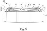
- the Fig. 3 shows a side view of a lock nut 20 according to the invention.
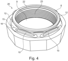
- the shaped collar 8 in addition to a stepped section 21, has, in the circumferential direction, alternating first sections 15 with an undercut section 17 and a curved section 19 and second sections 12 with a reduced wall thickness of the shaped collar 8.
- the second sections 12 of the shaped collar 8 with reduced wall thickness have such a reduced wall thickness that centrally or internally in the sections 12 with reduced wall thickness, the reduction in the wall thickness is so great that slots 10 are formed or formed in the shaped collar 8, which extend from the radial outer side 16 into the radially inner gap between the internally threaded bore 9 and the inner end face 11.
- the sections 12 of the shaped collar 8 with Reduced wall thicknesses allow adjustment or modification of the spring action of the shaped collar 8 and thus also influence the generation of the braking torque on a screw bolt.
- the areas 15, which have the undercut section 17 and the curved section 19, also contribute to the advantageous spring action of the shaped collar 8 and also stabilize the connection between the nut body 1 and the shaped collar 8.
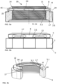
- the representation of the Fig. 5a shows a further embodiment of a lock nut 20 according to the invention.
- the embodiment has similarities or overlaps with the embodiment of the Figures 3 and 4 .
- Fig. 5a can be removed, the lock nut 20 of the Fig. 5a in contrast to the embodiment the Figures 3 and 4 no stepped section 21.
- the formed collar 8 is designed such that the thickness or width of the formed collar 8 increases with increasing approach to the outer surface 14 and with increasing approach to the locking thread 22, but without forming a corresponding step or stepped section 21.
- the continuous increase in the thickness of the formed collar radially inward towards the locking thread 22 has the advantage that sufficient material or a sufficient material thickness is formed on the inner end face 11 in the axial direction to provide a locking thread 22 with a sufficient number of turns or with a sufficiently large turn section.
- the relatively complex formation of the stepped section can be dispensed with. If necessary, it is even possible to form the wall thickness of the formed collar, which increases with increasing axial distance radially inward, without machining the formed collar, simply by forming an annular collar with a correspondingly increasing wall thickness in the axial direction.
- the front face 3 is in the embodiment of the Fig. 5a essentially horizontal or planar in the radial direction and parallel to the radial direction.
- the end face 3 points away from the nut body 1.
- this concerns a radially outer part 3.1 of the end face 3.
- auxiliary line H On the radially outer side of the auxiliary line H, a projection section 24 adjoins the end face 3 in the axial direction A with increasing distance from the nut body.
- auxiliary line H runs parallel to the axial direction A through the radially outermost point of the radial outer side 16 of the shaped collar 8.
- the formulation according to which an undercut section 17 is formed in the axial direction A adjacent to the end face 3 on a radial outer side 16 of the shaped collar 8 by the shaped collar is intended accordingly to include embodiments in which the radially outer end face 3.1 exists, since otherwise no end face is available from which, starting in the axial direction, the radially outer side or the radial outer side of the shaped collar can form an undercut section 17 at all.
- the above formulation is to be understood in such a way that the undercut section 17 is precisely the section or region in the radially inner region of the auxiliary line H. In other words, this means that the undercut section 17 in the representation of the Fig. 5a is limited by a part of the radially outer end face 3.1, the shaped collar 8 and the auxiliary line H.
- the undercut section 17 has a base section 25 which is adjacent to the end face 3 in the axial direction and which runs over a certain length in the axial direction parallel to the axial direction A.
- An undercut section with such a straight-line base section 25 of the innermost area in the radial direction R allows in a particularly advantageous manner subsequent, in particular machining, production or reworking of the undercut section 17.
- end face 3 There are two end faces 3 at opposite ends of the nut body 1 in the axial direction A.
- the end face 3 facing the shaped collar which on a radially outer section, namely the end face 3.1, helps to define the undercut section 17, has on a radially inner side of the nut body 1, as shown in the sectional view of Fig. 5a recognizable, a further section 3.2, which is arranged further up or closer to the shaped collar 8 in the axial direction than the outer end face 3.1 in the radial direction R.
- This residual undercut 26 is also, for example, the Fig. 5c in the area of the left cut surface 27 below a section 12 with reduced wall thickness.
- the undercut section 17 or at least the remaining undercut 26 of the undercut section 17 is therefore radially circumferential and uninterrupted.
- This embodiment in particular in conjunction with the end faces 3, 3, 1 running flat in the radial direction R and parallel to the radial direction, allows particularly advantageously, a simple machining or post-machining of the undercut section 17.
- the Figures 6a to 6c have with the design of the Figures 5a to 5c common that no step section 21 is formed, but the shaped collar 8 increases continuously with axial distance from the end face 3 and with increasing proximity to the inner end face 11 for forming the locking thread 22, in order to be able to provide a sufficiently wide or high surface in the axial direction A for forming the locking thread 22.
- the lock nut 20 of the embodiment of the Figures 6a to 6c There are no sections in the mold collar with reduced wall thickness.
- the radially outer end face 3.1 although flat, does not run parallel to the radial direction R but slopes radially outward in the form of a shoulder 28.
- the radially inner section 3.2 of the end face 3 runs again higher than the end face 3.1, parallel to the radial direction R.
- the section of the undercut section 17 which is furthest inward in the radial direction R also runs in the embodiment of the Figures 6a to 6c , as shown, is not curved over any significant area parallel to the axial direction A, but rather is continuously curved starting from the inclined shoulder 28.
- the undercut section 17 can also be formed particularly easily and effectively in this embodiment.
- the outer surface 14 is relatively small or designed as a relatively thin annular disc and merges directly into an upper shoulder section 29 of the shaped collar 8, which runs inclined radially outwards with respect to the radial direction R, which then in turn merges into a curved section 19, so that in the interior of the shaped collar 8, in particular by the upper shoulder section 29, the increasing thickness or increasing height of the shaped collar 8 is formed with increasing approach to the inner end face 11.
- this design of the radial outer side of the molded collar offers particular manufacturing advantages. Furthermore, it can positively influence the spring properties of the molded collar.
Landscapes
- Engineering & Computer Science (AREA)
- General Engineering & Computer Science (AREA)
- Mechanical Engineering (AREA)
- Braking Arrangements (AREA)
- Forging (AREA)
Claims (9)
- Écrou de blocage (20) comprenant une collerette façonnée (8) disposée sur une face frontale (3) d'un corps d'écrou (1) et liée intégralement au corps d'écrou (1), la collerette façonnée (8) ayant une face frontale intérieure (11) concentrique avec un trou à filetage intérieur (9) du corps d'écrou (1), la face frontale intérieure (11) ayant une distance du trou à filetage intérieur (9) dans une direction axiale (A) et ayant un filetage intérieur de blocage (22) décalé d'un filetage intérieur (23) du trou à filetage intérieur (9), la collerette façonnée (8) formant une partie contre-dépouillée (17) sur un côté extérieur radial (16) de la collerette façonnée (8) au voisinage de la face frontale (3) dans la direction axiale (A), la collerette façonnée (8) formant une partie courbée (19) sur un côté extérieur radial (16), de préférence au voisinage d'une surface extérieure (14), la partie courbée (19) ayant un contour circulaire ou elliptique,
caractérisé en ce que
la partie contre-dépouillée (17) et/ou la partie courbée (19) est formée en sections dans une direction circonférentielle. - Écrou de blocage selon la revendication 1,
caractérisé en ce que
la collerette façonnée (8) forme une partie de gradin (21) sur un côté extérieur radial (16), de préférence au voisinage d'une surface extérieure (14) et/ou une partie courbée (19), la partie de gradin (21) s'étendant de plus en plus dans la direction axiale lorsqu'elle s'approche de la surface extérieure (14), de préférence dans la direction axiale (A). - Écrou de blocage selon la revendication 2,
caractérisé en ce que
dans la direction circonférentielle, des parties (15) ayant la partie contre-dépouillée (17) et/ou la partie courbée (19) alternent avec des parties (12) de la collerette façonnée (8) qui ont une épaisseur de paroi réduite. - Écrou de blocage selon la revendication 3,
caractérisé en ce que
les parties (12) de la collerette façonnée (8) qui ont une épaisseur de paroi réduite enclavent des fentes (10) dans la collerette façonnée (8), les fentes (10) s'étendant parallèlement à la face frontale (3). - Écrou de blocage selon la revendication 3 ou 4,
caractérisé en ce que
les parties (12) de la collerette façonnée (8) qui ont une épaisseur de paroi réduite sont planes et s'étendent dans la direction axiale (A) sur le côté extérieur radial (16) de la collerette façonnée (8). - Écrou de blocage selon l'une quelconque des revendications 3 à 5,
caractérisé en ce que
des parties (12) de la collerette façonnée (8) qui ont une épaisseur de paroi réduite sont réparties uniformément sur la circonférence sur le côté extérieur radial (16) de la collerette façonnée (8). - Écrou de blocage selon l'une quelconque des revendications 1 à 6,
caractérisé en ce que
la collerette façonnée (8) est formée par façonnage d'une collerette annulaire. - Écrou de blocage selon l'une quelconque des revendications 1 à 7,
caractérisé en ce que
la collerette façonnée (8) est formée par usinage. - Écrou de blocage selon l'une quelconque des revendications 1 à 8,
caractérisé en ce que
la collerette façonnée (8) a un surface extérieure et/ou intérieure (13, 14) qui est plane, notamment sans creux, sur la circonférence entière, au moins au voisinage de la face frontale intérieure (11).
Applications Claiming Priority (2)
| Application Number | Priority Date | Filing Date | Title |
|---|---|---|---|
| DE102021112290.2A DE102021112290A1 (de) | 2021-05-11 | 2021-05-11 | Sicherungsmutter mit Federspeicher-Formkragen |
| PCT/EP2022/062204 WO2022238239A1 (fr) | 2021-05-11 | 2022-05-05 | Contre-écrou à collet en forme d'accumulateur à ressort |
Publications (3)
| Publication Number | Publication Date |
|---|---|
| EP4337870A1 EP4337870A1 (fr) | 2024-03-20 |
| EP4337870B1 true EP4337870B1 (fr) | 2025-07-09 |
| EP4337870C0 EP4337870C0 (fr) | 2025-07-09 |
Family
ID=81974979
Family Applications (1)
| Application Number | Title | Priority Date | Filing Date |
|---|---|---|---|
| EP22728362.9A Active EP4337870B1 (fr) | 2021-05-11 | 2022-05-05 | Contre-écrou à collet en forme d'accumulateur à ressort |
Country Status (6)
| Country | Link |
|---|---|
| US (1) | US20240240664A1 (fr) |
| EP (1) | EP4337870B1 (fr) |
| CN (1) | CN117396680A (fr) |
| DE (1) | DE102021112290A1 (fr) |
| ES (1) | ES3039560T3 (fr) |
| WO (1) | WO2022238239A1 (fr) |
Families Citing this family (2)
| Publication number | Priority date | Publication date | Assignee | Title |
|---|---|---|---|---|
| DE102024002627A1 (de) | 2024-08-13 | 2026-02-19 | SPIETH-Maschinenelemente GmbH & Co. KG. | Verfahren zum Herstellen einer Festlegevorrichtung nebst einer Festlegevorrichtung |
| US12601262B1 (en) | 2025-04-30 | 2026-04-14 | Honeywell International Inc. | Gas turbine engines, methods of securing rotating components therein with threaded nuts, and the threaded nuts |
Citations (1)
| Publication number | Priority date | Publication date | Assignee | Title |
|---|---|---|---|---|
| JPS60132116A (ja) * | 1983-12-20 | 1985-07-15 | 山内 進 | ゆるみ止めナツト及びその製造方法 |
Family Cites Families (18)
| Publication number | Priority date | Publication date | Assignee | Title |
|---|---|---|---|---|
| US2196637A (en) * | 1937-10-07 | 1940-04-09 | Richard W Luce | Lock nut |
| US2260531A (en) * | 1939-02-02 | 1941-10-28 | Luce Richard Waterman | Lock nut |
| US2304310A (en) * | 1939-04-11 | 1942-12-08 | Richard W Luce | Thread locking device |
| US2265661A (en) * | 1939-04-11 | 1941-12-09 | Richard W Luce | Threaded locking device |
| US2320785A (en) | 1940-03-07 | 1943-06-01 | Richard W Luce | Threaded locking device |
| US2429832A (en) * | 1943-02-05 | 1947-10-28 | Richard W Luce | Method of making threaded locking devices |
| US2376927A (en) | 1943-05-22 | 1945-05-29 | Richard W Luce | Threaded locking device |
| US2412896A (en) * | 1943-06-16 | 1946-12-17 | Richard W Luce | Threaded locking device |
| US2390662A (en) * | 1944-06-28 | 1945-12-11 | Walter M Perry | One-piece self-locking nut |
| US2551102A (en) | 1945-07-18 | 1951-05-01 | Boots Aircraft Nut Corp | Lock nut |
| US2529093A (en) * | 1945-07-25 | 1950-11-07 | Richard W Luce | Lock nut |
| US2750980A (en) * | 1952-09-18 | 1956-06-19 | Jr John C Haggart | Lock nut having fastening zone and columnar supported locking zone |
| US3142325A (en) * | 1959-02-13 | 1964-07-28 | Penn Eng & Mfg Corp | Nut having segmented locking extension |
| US3265109A (en) * | 1962-09-14 | 1966-08-09 | Hanfland Curt Hermann | Safety nut |
| CN1435579A (zh) * | 2002-02-01 | 2003-08-13 | 名川政人 | 紧固件的结构、具有该结构的螺栓和螺母及其制造方法 |
| DE102005062045A1 (de) | 2005-12-22 | 2007-06-28 | Hartmut Flaig | Schraubmutter, Verfahren zu ihrer Herstellung und Werkzeug dafür |
| EA020006B1 (ru) | 2008-09-24 | 2014-07-30 | Хартмут Флайг | Гайка, а также способ и инструмент для ее изготовления |
| DE102011052266A1 (de) | 2010-12-22 | 2012-08-02 | Hartmut Flaig | Selbstsichernde Befestigungsmittel sowie Befestigungsanordnung |
-
2021
- 2021-05-11 DE DE102021112290.2A patent/DE102021112290A1/de active Pending
-
2022
- 2022-05-05 US US18/290,100 patent/US20240240664A1/en active Pending
- 2022-05-05 WO PCT/EP2022/062204 patent/WO2022238239A1/fr not_active Ceased
- 2022-05-05 ES ES22728362T patent/ES3039560T3/es active Active
- 2022-05-05 EP EP22728362.9A patent/EP4337870B1/fr active Active
- 2022-05-05 CN CN202280037965.0A patent/CN117396680A/zh active Pending
Patent Citations (1)
| Publication number | Priority date | Publication date | Assignee | Title |
|---|---|---|---|---|
| JPS60132116A (ja) * | 1983-12-20 | 1985-07-15 | 山内 進 | ゆるみ止めナツト及びその製造方法 |
Also Published As
| Publication number | Publication date |
|---|---|
| EP4337870A1 (fr) | 2024-03-20 |
| DE102021112290A1 (de) | 2022-11-17 |
| CN117396680A (zh) | 2024-01-12 |
| EP4337870C0 (fr) | 2025-07-09 |
| US20240240664A1 (en) | 2024-07-18 |
| ES3039560T3 (en) | 2025-10-22 |
| WO2022238239A1 (fr) | 2022-11-17 |
Similar Documents
| Publication | Publication Date | Title |
|---|---|---|
| EP2622244B2 (fr) | Agencement de roue dentée et procédé de fabrication d'un emboîtement à baïonnette | |
| EP2449272B1 (fr) | Contre-écrou | |
| EP0627568B1 (fr) | Elément de connection et de centrage par insertion à force, en particulier boulon de roue | |
| EP2757299B1 (fr) | Dispositif de serrage de tuyau | |
| EP2594813B1 (fr) | Elément de rivet aveugle | |
| EP0807025B1 (fr) | Roue de vehicule et procede pour sa fabrication | |
| WO1982002579A1 (fr) | Ecrou encastrable | |
| EP1502033A2 (fr) | Ecrou et son procede de production | |
| DE102016101910A1 (de) | Kunststoff-Gewindeelement sowie Verbindungsanordnung bestehend aus einem Kunststoffträgerteil und einem Kunststoff-Gewindeelement | |
| WO2022238239A1 (fr) | Contre-écrou à collet en forme d'accumulateur à ressort | |
| WO2013102453A1 (fr) | Vis auto-taraudeuse | |
| WO2015063293A1 (fr) | Douille métallique et son procédé de fabrication | |
| EP3791103B1 (fr) | Couplage de connexion | |
| WO2017001127A1 (fr) | Transmission par vis sans fin et actionneur pourvu d'une transmission par vis sans fin | |
| DE102013203150A1 (de) | Verfahren zum Herstellen einer Betonschraube | |
| DE102013203148A1 (de) | Herstellungsverfahren für Schrauben und Betonschraube | |
| DE102018003247A1 (de) | Festlegevorrichtung | |
| DE102012222595A1 (de) | Stehlagergehäuse | |
| EP2254714B1 (fr) | Procédé de production d'un élément taraudé, élément taraudé et assemblage par vissage correspondants | |
| WO2010115502A1 (fr) | Rotor pourvu d'une sécurité contre la surcharge pour une limitation du couple de rotation | |
| DE4313845C1 (de) | Sicherungsmutter | |
| DE102015111456A1 (de) | Schraube für eine elektrische Kontaktverbindung | |
| EP3649068B1 (fr) | Axe de rouleau de convoyeur | |
| EP1923584A2 (fr) | Ecrou embouti | |
| DE19708286B4 (de) | Blechteil |
Legal Events
| Date | Code | Title | Description |
|---|---|---|---|
| STAA | Information on the status of an ep patent application or granted ep patent |
Free format text: STATUS: UNKNOWN |
|
| STAA | Information on the status of an ep patent application or granted ep patent |
Free format text: STATUS: THE INTERNATIONAL PUBLICATION HAS BEEN MADE |
|
| PUAI | Public reference made under article 153(3) epc to a published international application that has entered the european phase |
Free format text: ORIGINAL CODE: 0009012 |
|
| STAA | Information on the status of an ep patent application or granted ep patent |
Free format text: STATUS: REQUEST FOR EXAMINATION WAS MADE |
|
| 17P | Request for examination filed |
Effective date: 20231127 |
|
| AK | Designated contracting states |
Kind code of ref document: A1 Designated state(s): AL AT BE BG CH CY CZ DE DK EE ES FI FR GB GR HR HU IE IS IT LI LT LU LV MC MK MT NL NO PL PT RO RS SE SI SK SM TR |
|
| DAV | Request for validation of the european patent (deleted) | ||
| DAX | Request for extension of the european patent (deleted) | ||
| GRAP | Despatch of communication of intention to grant a patent |
Free format text: ORIGINAL CODE: EPIDOSNIGR1 |
|
| STAA | Information on the status of an ep patent application or granted ep patent |
Free format text: STATUS: GRANT OF PATENT IS INTENDED |
|
| INTG | Intention to grant announced |
Effective date: 20250219 |
|
| GRAS | Grant fee paid |
Free format text: ORIGINAL CODE: EPIDOSNIGR3 |
|
| GRAA | (expected) grant |
Free format text: ORIGINAL CODE: 0009210 |
|
| STAA | Information on the status of an ep patent application or granted ep patent |
Free format text: STATUS: THE PATENT HAS BEEN GRANTED |
|
| AK | Designated contracting states |
Kind code of ref document: B1 Designated state(s): AL AT BE BG CH CY CZ DE DK EE ES FI FR GB GR HR HU IE IS IT LI LT LU LV MC MK MT NL NO PL PT RO RS SE SI SK SM TR |
|
| REG | Reference to a national code |
Ref country code: GB Ref legal event code: FG4D Free format text: NOT ENGLISH |
|
| REG | Reference to a national code |
Ref country code: CH Ref legal event code: EP |
|
| REG | Reference to a national code |
Ref country code: IE Ref legal event code: FG4D Free format text: LANGUAGE OF EP DOCUMENT: GERMAN |
|
| REG | Reference to a national code |
Ref country code: DE Ref legal event code: R096 Ref document number: 502022004602 Country of ref document: DE |
|
| U01 | Request for unitary effect filed |
Effective date: 20250721 |
|
| U07 | Unitary effect registered |
Designated state(s): AT BE BG DE DK EE FI FR IT LT LU LV MT NL PT RO SE SI Effective date: 20250728 |
|
| PG25 | Lapsed in a contracting state [announced via postgrant information from national office to epo] |
Ref country code: IS Free format text: LAPSE BECAUSE OF FAILURE TO SUBMIT A TRANSLATION OF THE DESCRIPTION OR TO PAY THE FEE WITHIN THE PRESCRIBED TIME-LIMIT Effective date: 20251109 |
|
| PG25 | Lapsed in a contracting state [announced via postgrant information from national office to epo] |
Ref country code: NO Free format text: LAPSE BECAUSE OF FAILURE TO SUBMIT A TRANSLATION OF THE DESCRIPTION OR TO PAY THE FEE WITHIN THE PRESCRIBED TIME-LIMIT Effective date: 20251009 |
|
| PG25 | Lapsed in a contracting state [announced via postgrant information from national office to epo] |
Ref country code: HR Free format text: LAPSE BECAUSE OF FAILURE TO SUBMIT A TRANSLATION OF THE DESCRIPTION OR TO PAY THE FEE WITHIN THE PRESCRIBED TIME-LIMIT Effective date: 20250709 |
|
| PG25 | Lapsed in a contracting state [announced via postgrant information from national office to epo] |
Ref country code: GR Free format text: LAPSE BECAUSE OF FAILURE TO SUBMIT A TRANSLATION OF THE DESCRIPTION OR TO PAY THE FEE WITHIN THE PRESCRIBED TIME-LIMIT Effective date: 20251010 |
|
| PG25 | Lapsed in a contracting state [announced via postgrant information from national office to epo] |
Ref country code: PL Free format text: LAPSE BECAUSE OF FAILURE TO SUBMIT A TRANSLATION OF THE DESCRIPTION OR TO PAY THE FEE WITHIN THE PRESCRIBED TIME-LIMIT Effective date: 20250709 |
|
| PG25 | Lapsed in a contracting state [announced via postgrant information from national office to epo] |
Ref country code: RS Free format text: LAPSE BECAUSE OF FAILURE TO SUBMIT A TRANSLATION OF THE DESCRIPTION OR TO PAY THE FEE WITHIN THE PRESCRIBED TIME-LIMIT Effective date: 20251009 |
|
| PG25 | Lapsed in a contracting state [announced via postgrant information from national office to epo] |
Ref country code: SM Free format text: LAPSE BECAUSE OF FAILURE TO SUBMIT A TRANSLATION OF THE DESCRIPTION OR TO PAY THE FEE WITHIN THE PRESCRIBED TIME-LIMIT Effective date: 20250709 |
|
| PG25 | Lapsed in a contracting state [announced via postgrant information from national office to epo] |
Ref country code: CZ Free format text: LAPSE BECAUSE OF FAILURE TO SUBMIT A TRANSLATION OF THE DESCRIPTION OR TO PAY THE FEE WITHIN THE PRESCRIBED TIME-LIMIT Effective date: 20250709 |
|
| PG25 | Lapsed in a contracting state [announced via postgrant information from national office to epo] |
Ref country code: SK Free format text: LAPSE BECAUSE OF FAILURE TO SUBMIT A TRANSLATION OF THE DESCRIPTION OR TO PAY THE FEE WITHIN THE PRESCRIBED TIME-LIMIT Effective date: 20250709 |
|
| PLBE | No opposition filed within time limit |
Free format text: ORIGINAL CODE: 0009261 |
|
| STAA | Information on the status of an ep patent application or granted ep patent |
Free format text: STATUS: NO OPPOSITION FILED WITHIN TIME LIMIT |