EP4337876B1 - Agencement de frein avec un frein, un adaptateur et un engrenage - Google Patents
Agencement de frein avec un frein, un adaptateur et un engrenage Download PDFInfo
- Publication number
- EP4337876B1 EP4337876B1 EP22723545.4A EP22723545A EP4337876B1 EP 4337876 B1 EP4337876 B1 EP 4337876B1 EP 22723545 A EP22723545 A EP 22723545A EP 4337876 B1 EP4337876 B1 EP 4337876B1
- Authority
- EP
- European Patent Office
- Prior art keywords
- brake
- housing
- magnet body
- shaft
- arrangement according
- Prior art date
- Legal status (The legal status is an assumption and is not a legal conclusion. Google has not performed a legal analysis and makes no representation as to the accuracy of the status listed.)
- Active
Links
Images


Classifications
-
- F—MECHANICAL ENGINEERING; LIGHTING; HEATING; WEAPONS; BLASTING
- F16—ENGINEERING ELEMENTS AND UNITS; GENERAL MEASURES FOR PRODUCING AND MAINTAINING EFFECTIVE FUNCTIONING OF MACHINES OR INSTALLATIONS; THERMAL INSULATION IN GENERAL
- F16D—COUPLINGS FOR TRANSMITTING ROTATION; CLUTCHES; BRAKES
- F16D63/00—Brakes not otherwise provided for; Brakes combining more than one of the types of groups F16D49/00 - F16D61/00
- F16D63/002—Brakes with direct electrical or electro-magnetic actuation
-
- B—PERFORMING OPERATIONS; TRANSPORTING
- B61—RAILWAYS
- B61C—LOCOMOTIVES; MOTOR RAILCARS
- B61C3/00—Electric locomotives or railcars
-
- B—PERFORMING OPERATIONS; TRANSPORTING
- B62—LAND VEHICLES FOR TRAVELLING OTHERWISE THAN ON RAILS
- B62B—HAND-PROPELLED VEHICLES, e.g. HAND CARTS OR PERAMBULATORS; SLEDGES
- B62B5/00—Accessories or details specially adapted for hand carts
- B62B5/0026—Propulsion aids
- B62B5/0033—Electric motors
- B62B5/0036—Arrangements of motors
- B62B5/0043—One motor drives one wheel
-
- F—MECHANICAL ENGINEERING; LIGHTING; HEATING; WEAPONS; BLASTING
- F16—ENGINEERING ELEMENTS AND UNITS; GENERAL MEASURES FOR PRODUCING AND MAINTAINING EFFECTIVE FUNCTIONING OF MACHINES OR INSTALLATIONS; THERMAL INSULATION IN GENERAL
- F16D—COUPLINGS FOR TRANSMITTING ROTATION; CLUTCHES; BRAKES
- F16D55/00—Brakes with substantially-radial braking surfaces pressed together in axial direction, e.g. disc brakes
- F16D55/02—Brakes with substantially-radial braking surfaces pressed together in axial direction, e.g. disc brakes with axially-movable discs or pads pressed against axially-located rotating members
-
- F—MECHANICAL ENGINEERING; LIGHTING; HEATING; WEAPONS; BLASTING
- F16—ENGINEERING ELEMENTS AND UNITS; GENERAL MEASURES FOR PRODUCING AND MAINTAINING EFFECTIVE FUNCTIONING OF MACHINES OR INSTALLATIONS; THERMAL INSULATION IN GENERAL
- F16D—COUPLINGS FOR TRANSMITTING ROTATION; CLUTCHES; BRAKES
- F16D65/00—Parts or details
- F16D65/005—Components of axially engaging brakes not otherwise provided for
- F16D65/0081—Brake covers
-
- F—MECHANICAL ENGINEERING; LIGHTING; HEATING; WEAPONS; BLASTING
- F16—ENGINEERING ELEMENTS AND UNITS; GENERAL MEASURES FOR PRODUCING AND MAINTAINING EFFECTIVE FUNCTIONING OF MACHINES OR INSTALLATIONS; THERMAL INSULATION IN GENERAL
- F16D—COUPLINGS FOR TRANSMITTING ROTATION; CLUTCHES; BRAKES
- F16D65/00—Parts or details
- F16D65/14—Actuating mechanisms for brakes; Means for initiating operation at a predetermined position
- F16D65/16—Actuating mechanisms for brakes; Means for initiating operation at a predetermined position arranged in or on the brake
- F16D65/18—Actuating mechanisms for brakes; Means for initiating operation at a predetermined position arranged in or on the brake adapted for drawing members together, e.g. for disc brakes
-
- F—MECHANICAL ENGINEERING; LIGHTING; HEATING; WEAPONS; BLASTING
- F16—ENGINEERING ELEMENTS AND UNITS; GENERAL MEASURES FOR PRODUCING AND MAINTAINING EFFECTIVE FUNCTIONING OF MACHINES OR INSTALLATIONS; THERMAL INSULATION IN GENERAL
- F16D—COUPLINGS FOR TRANSMITTING ROTATION; CLUTCHES; BRAKES
- F16D55/00—Brakes with substantially-radial braking surfaces pressed together in axial direction, e.g. disc brakes
- F16D2055/0004—Parts or details of disc brakes
- F16D2055/0033—Fully-enclosing housings
-
- F—MECHANICAL ENGINEERING; LIGHTING; HEATING; WEAPONS; BLASTING
- F16—ENGINEERING ELEMENTS AND UNITS; GENERAL MEASURES FOR PRODUCING AND MAINTAINING EFFECTIVE FUNCTIONING OF MACHINES OR INSTALLATIONS; THERMAL INSULATION IN GENERAL
- F16D—COUPLINGS FOR TRANSMITTING ROTATION; CLUTCHES; BRAKES
- F16D2121/00—Type of actuator operation force
- F16D2121/18—Electric or magnetic
- F16D2121/20—Electric or magnetic using electromagnets
- F16D2121/22—Electric or magnetic using electromagnets for releasing a normally applied brake
Definitions
- the invention relates to a brake arrangement comprising a brake, an adapter and a gear.
- the invention is therefore based on the object of designing a brake arrangement as compact as possible.
- the object is achieved in the brake arrangement according to the features specified in claim 1.
- a first toothed part is connected in a rotationally fixed manner to the input shaft of the transmission,
- the first gear part engages with another gear part of the transmission.
- the cover part together with the flange part, performs the housing function for the brake and/or forms the housing and/or forms the housing itself. This is advantageous because the brake can be attached to the gearbox in a protected manner.
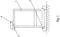
- a drive wheel driven by an electric drive is arranged on the underside of the frame of the storage and retrieval machine,
- the drive wheel is designed as a rail wheel.
- the advantage here is that the drive is close to the ground.
- the drive is also equipped with an additional brake, allowing braking instead of acceleration.
- the drive wheel 3 is designed as a rail wheel and rolls on a rail arranged on the floor of the system comprising the storage and retrieval machine.
- the input shaft 44 of the gearbox has a smaller diameter than the output shaft of the gearbox because the input shaft 44 is subjected to a smaller torque.
- the gear 30 is designed as an angular gear so that the input shaft 44 is aligned perpendicular to the output shaft.
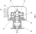
- the invention provides an electromagnetically actuated brake which is connected to the gear 30 via an adapter.
- the adapter housing 40 is constructed in two parts and accommodates a bearing for the rotatable support of the shaft 44.
- the bearing is housed in both the first and second parts of the adapter housing 40, thus centering the two parts relative to each other.
- the flange part 41 is connected to one of the two parts.
- the brake is enclosed by a cover 42, which is connected to the flange part 41 and thus forms a housing for the brake.
- a terminal box 43 is attached to the outside of the cover 42, to which the electrical supply lines of a brake coil are routed.
- the coil can therefore be energized.
- the brake has a magnetic body 47 made of ferromagnetic material, which is connected to the flange part 41 in a rotationally fixed manner.
- An annular recess is formed in the magnet body 47, in which the coil formed as a toroidal coil is received.
- the shaft 44 extends through the magnet body 47.
- a ferromagnetic armature disk 46 which is connected to the magnetic body 47 in a rotationally fixed manner but can be moved back and forth axially, i.e. parallel to the direction of the axis of rotation of the shaft 44.
- An annular driver 45 is connected to the shaft 44 in a rotationally fixed manner, in particular by means of a keyway.
- the driver 45 has external teeth.
- a disc-shaped brake pad carrier is mounted on the driver 45 and has internal teeth that mesh with the external teeth.
- the brake pad carrier is connected to the shaft 44 in a rotationally fixed manner, but can be moved axially back and forth.
- the brake pad carrier is arranged between the flange part 41 and the armature plate 46 and preferably has brake pads axially on both sides.
- the spring elements press the armature disk 46 onto the brake pad carrier, which is thus pressed towards the flange part 41, in particular onto a finely machined surface of the flange part 41 which functions as a braking surface.
- the brake is thus applied, generates a braking torque and enables the gear 30 to amplify this braking torque towards the output shaft in accordance with the transmission ratio of the gear 30.
- the storage and retrieval machine is preferably designed as a rail vehicle.
- the gear 30 is designed as a spur gear, in particular as a parallel shaft gear.
- an angle sensor can be arranged at the end region of the shaft 44 protruding from the magnetic body 47 in order to detect the angular position of the shaft 44.
Landscapes
- Engineering & Computer Science (AREA)
- General Engineering & Computer Science (AREA)
- Mechanical Engineering (AREA)
- Transportation (AREA)
- Chemical & Material Sciences (AREA)
- Combustion & Propulsion (AREA)
- Braking Arrangements (AREA)
Claims (12)
- Système de freinage, comprenant un frein, un adaptateur et une transmission (30), l'adaptateur présentant un carter d'adaptateur (40) relié à une partie carter de la transmission (30),une partie bride (41) du frein étant reliée au carter d'adaptateur sur le côté du carter d'adaptateur (40) qui se trouve à l'opposé de la boîte de vitesses,une partie capot (42) du frein étant reliée à la partie bride (41),au moins un palier (40), qui permet une mise sur palier rotative de l'arbre d'entraînement (44) de la transmission, étant accueilli dans le carter d'adaptateur,caractérisé en ce queune surface de freinage, en particulier une surface finement usinée, est formée sur la partie bride (41).
- Système de freinage selon la revendication 1,
caractérisé en ce queune première partie denture est reliée de manière solidaire en rotation à l'arbre d'entraînement de la transmission (30),la première partie denture étant en prise avec une autre partie denture de la transmission (30). - Système de freinage selon l'une quelconque des revendications précédentes, caractérisé en ce que
la partie capot (42) remplit, en collaboration avec la partie bride (41), la fonction de carter pour le frein et/ou est constitutive d'un carter et/ou forme le carter. - Système de freinage selon l'une quelconque des revendications précédentes, caractérisé en ce queun entraîneur (45) est relié de manière solidaire en rotation à l'arbre (44),un support de garniture de frein étant relié de manière solidaire en rotation à l'entraîneur (45) et pouvant être déplacé de manière axiale, en particulier pouvant être déplacé en va-et-vient, par rapport au corps magnétique (47),un corps magnétique (47) du frein étant relié de manière solidaire en rotation à la partie bride (41),une bobine alimentable étant accueillie dans le corps magnétique,un disque d'induit (46) étant agencé, en particulier pouvant être déplacé en va-et-vient, axialement entre le support de garniture de frein et le corps magnétique,le disque d'induit étant relié de manière solidaire en rotation au corps magnétique (47) et étant agencé de manière à pouvoir être déplacé axialement par rapport au corps magnétique (47), en particulier au moyen de boulons fixés au corps magnétique et traversant des évidements du disque d'induit,des éléments formant ressort appuyés contre le corps magnétique appuyant sur le disque d'induit (46).
- Système de freinage selon la revendication 4,
caractérisé en ce quel'arbre (44) traverse le corps magnétique (46),un capteur d'angle qui permet de détecter la position angulaire de l'arbre à l'intérieur de la partie capot pouvant en particulier être raccordé et/ou agencé sur la région d'extrémité de l'arbre qui se trouve à l'opposé du carter d'adaptateur (40),un arbre de capteur du capteur d'angle étant en particulier relié de manière solidaire en rotation à l'arbre et un carter du capteur d'angle étant en particulier relié au corps magnétique (46) et/ou à la partie capot. - Système de freinage selon l'une quelconque des revendications précédentes, caractérisé en ce que
le frein est relié directement à la transmission (30) par l'intermédiaire de l'adaptateur, en particulier en ce qu'aucun moteur ou moteur électrique n'est interposé. - Système de freinage selon l'une quelconque des revendications précédentes, caractérisé en ce que
une boîte de raccordement (43), vers laquelle mènent les conduites d'alimentation du frein, en particulier de la bobine, est fixée sur le côté extérieur de la partie capot (42). - Système de freinage selon l'une quelconque des revendications précédentes, caractérisé en ce quele palier accueilli dans le carter d'adaptateur (40) centre l'une par rapport à l'autre deux parties du carter d'adaptateur formant le carter d'adaptateur,l'une des parties étant reliée à la partie bride (41) qui présente une ou la surface de freinage du frein.
- Système de freinage selon l'une quelconque des revendications précédentes, caractérisé en ce que
le carter d'adaptateur (40) présente une région parallélépipédique. - Transstockeur comprenant un système de freinage selon l'une quelconque des revendications précédentes,
caractérisé en ce que
une roue (2) faisant office de guide latéral, en particulier une roue de guidage, est reliée de manière solidaire en rotation à l'arbre de sortie de la transmission (30). - Transstockeur selon la revendication 10,
caractérisé en ce que
la roue (2) est agencée sur le côté supérieur d'un châssis (1) du transstockeur. - Transstockeur selon la revendication 10 ou 11,
caractérisé en ce queune roue d'entraînement (3) entraînée par un entraînement électrique est agencée sur le côté inférieur du châssis (1) du transstockeur,la roue d'entraînement (3) étant en particulier mise en œuvre sous la forme d'une roue ferroviaire et le transstockeur étant ainsi mis en œuvre sous la forme d'un véhicule ferroviaire.
Applications Claiming Priority (3)
| Application Number | Priority Date | Filing Date | Title |
|---|---|---|---|
| CN202110517160.3A CN115342139A (zh) | 2021-05-12 | 2021-05-12 | 制动装置和货架操作机 |
| DE102022000114 | 2022-01-12 | ||
| PCT/EP2022/025155 WO2022237999A1 (fr) | 2021-05-12 | 2022-04-19 | Ensemble frein comprenant un frein, un adaptateur et une transmission |
Publications (3)
| Publication Number | Publication Date |
|---|---|
| EP4337876A1 EP4337876A1 (fr) | 2024-03-20 |
| EP4337876B1 true EP4337876B1 (fr) | 2025-06-11 |
| EP4337876C0 EP4337876C0 (fr) | 2025-06-11 |
Family
ID=81654663
Family Applications (1)
| Application Number | Title | Priority Date | Filing Date |
|---|---|---|---|
| EP22723545.4A Active EP4337876B1 (fr) | 2021-05-12 | 2022-04-19 | Agencement de frein avec un frein, un adaptateur et un engrenage |
Country Status (4)
| Country | Link |
|---|---|
| US (1) | US20240255035A1 (fr) |
| EP (1) | EP4337876B1 (fr) |
| DE (1) | DE102022001331A1 (fr) |
| WO (1) | WO2022237999A1 (fr) |
Family Cites Families (15)
| Publication number | Priority date | Publication date | Assignee | Title |
|---|---|---|---|---|
| US4377094A (en) * | 1979-11-28 | 1983-03-22 | Logan Manufacturing Company | Liquid cooled disc brake for differential of a tracked vehicle |
| DE3205980C2 (de) * | 1982-02-19 | 1985-10-03 | Zahnradfabrik Friedrichshafen Ag, 7990 Friedrichshafen | Elektromagnetische Haltebremse |
| US5603395A (en) * | 1992-03-05 | 1997-02-18 | Easom Engineering & Mfg. Corp. | Electrically actuated disc stack having low response time due to reduced residual magnetism for use in drives, brakes and combinations thereof |
| DE4328210C1 (de) * | 1993-08-21 | 1994-09-08 | Habegger Maschf | Tragbare Seilzugmaschine |
| JP3982562B1 (ja) * | 2006-09-28 | 2007-09-26 | 株式会社Ihi | スタッカクレーン |
| DE102009007558A1 (de) * | 2009-02-04 | 2010-08-05 | Sew-Eurodrive Gmbh & Co. Kg | Spiroplan-Getriebe mit Kupplung |
| CN101823433B (zh) * | 2010-05-21 | 2013-01-02 | 徐工集团工程机械股份有限公司科技分公司 | 湿式制动驱动桥及具有该驱动桥的装载机 |
| US8615976B1 (en) * | 2010-06-21 | 2013-12-31 | Hydro-Gear Limited Partnership | Electric motor clutch/brake assembly |
| CN202441770U (zh) * | 2011-12-29 | 2012-09-19 | 徐州锐马重工机械有限公司 | 车辆电子驻车制动系统的制动器 |
| CN204371992U (zh) * | 2014-11-26 | 2015-06-03 | 黄洪权 | 带编码器旋转盘式制动器 |
| DE102015005360B3 (de) * | 2015-04-28 | 2016-06-23 | Sew-Eurodrive Gmbh & Co Kg | Getriebesystem |
| DE102016012501C5 (de) * | 2016-10-19 | 2022-08-04 | Sew-Eurodrive Gmbh & Co Kg | Getriebe, aufweisend eine Welle, ein Gehäuseteil und ein Adaptergehäuse |
| DE102017000845B4 (de) * | 2017-01-31 | 2022-06-02 | Sew-Eurodrive Gmbh & Co Kg | Elektromagnetisch betätigbare Bremsanordnung zum Abbremsen einer Welle und Elektromotor mit einer solchen Bremsanordnung |
| WO2019219243A1 (fr) * | 2018-05-14 | 2019-11-21 | Sew-Eurodrive Gmbh & Co. Kg | Système de freinage pour moteur electrique |
| CN115342139A (zh) * | 2021-05-12 | 2022-11-15 | Sew-传动设备(天津)有限公司 | 制动装置和货架操作机 |
-
2022
- 2022-04-19 DE DE102022001331.2A patent/DE102022001331A1/de active Pending
- 2022-04-19 WO PCT/EP2022/025155 patent/WO2022237999A1/fr not_active Ceased
- 2022-04-19 US US18/560,519 patent/US20240255035A1/en active Pending
- 2022-04-19 EP EP22723545.4A patent/EP4337876B1/fr active Active
Also Published As
| Publication number | Publication date |
|---|---|
| US20240255035A1 (en) | 2024-08-01 |
| DE102022001331A1 (de) | 2022-11-17 |
| WO2022237999A1 (fr) | 2022-11-17 |
| EP4337876A1 (fr) | 2024-03-20 |
| EP4337876C0 (fr) | 2025-06-11 |
Similar Documents
| Publication | Publication Date | Title |
|---|---|---|
| DE102005055085A1 (de) | Kombinierte Betriebs- und Feststellbremseinrichtung sowie Verfahren zur Durchführung einer Notbremsung | |
| WO2014094942A2 (fr) | Véhicule et transmission | |
| EP1872025B1 (fr) | Accouplement a friction pour au moins une roue porteuse d'un vehicule automoteur sur rails | |
| EP4337876B1 (fr) | Agencement de frein avec un frein, un adaptateur et un engrenage | |
| EP4341569B1 (fr) | Connexion arbre-moyeu et ensemble de freinage doté d'une connexion arbre-moyeu | |
| DE60205878T2 (de) | Brems-kupplung anordnung | |
| DE102009000712A1 (de) | Antriebsachse für eine fahrbare Hubeinrichtung | |
| WO2025093232A1 (fr) | Unité mobile et système doté d'un entrepôt industriel et d'une unité mobile | |
| DE102014012348A1 (de) | Elektromotor, aufweisend einen Stator und einen Rotor, und Verfahren zum Herstellen einer elektromotorisch angetriebenen Maschine | |
| DE102022004153A1 (de) | Bremsanordnung, insbesondere elektromagnetisch betätigbare Bremsanordnung | |
| EP1667892B2 (fr) | Dispositif servant a superposer des mouvements de braquage pour un systeme d'assistance de direction et procede pour faire fonctionner ce dispositif | |
| WO1999047405A1 (fr) | Dispositif d'assistance electrique pour direction | |
| DE102022000286A1 (de) | Elektromotor mit elektromagnetisch betätigbarer Bremse | |
| EP4537442B1 (fr) | Motoréducteur et système comprenant une électronique de commande et un motoréducteur | |
| EP3788268B1 (fr) | Accouplement pour un moteur électrique et moteur électrique avec un accouplement entre l'arbre du rotor et l'arbre d'un capteur d'angle | |
| DE102024120275B3 (de) | Radachssystem zum Antrieb von Antriebsrädern eines Kraftfahrzeugs | |
| DE102020110611B3 (de) | Getriebe für ein zumindest teilweise elektrisch betriebenes Fahrzeug | |
| DE3205980C2 (de) | Elektromagnetische Haltebremse | |
| WO1998034042A1 (fr) | Installation de freinage, en particulier pourvue d'un frein a disque du type a etrier flottant, pour un vehicule a moteur | |
| DE102022004299A1 (de) | Antrieb, aufweisend ein Getriebe mit einem Getriebegehäuse, eine elektromagnetisch betätigbare Bremsanordnung und einen Elektromotor | |
| EP4537443A1 (fr) | Moteur à engrenages doté d'un frein | |
| WO2025140804A1 (fr) | Moteur de ventilateur électrique comprenant des freins | |
| WO2023099026A1 (fr) | Entraînement présentant une transmission dotée d'un carter de transmission, ensemble frein à actionnement électromagnétique et moteur électrique | |
| DE102024129609A1 (de) | Getriebemotor, insbesondere für Kettenfördervorrichtung | |
| EP4702652A1 (fr) | Ensemble de freinage, en particulier pour un moteur électrique, pour freiner un arbre, et moteur à frein comprenant un moteur électrique et un ensemble de freinage |
Legal Events
| Date | Code | Title | Description |
|---|---|---|---|
| STAA | Information on the status of an ep patent application or granted ep patent |
Free format text: STATUS: UNKNOWN |
|
| STAA | Information on the status of an ep patent application or granted ep patent |
Free format text: STATUS: THE INTERNATIONAL PUBLICATION HAS BEEN MADE |
|
| PUAI | Public reference made under article 153(3) epc to a published international application that has entered the european phase |
Free format text: ORIGINAL CODE: 0009012 |
|
| STAA | Information on the status of an ep patent application or granted ep patent |
Free format text: STATUS: REQUEST FOR EXAMINATION WAS MADE |
|
| 17P | Request for examination filed |
Effective date: 20231212 |
|
| AK | Designated contracting states |
Kind code of ref document: A1 Designated state(s): AL AT BE BG CH CY CZ DE DK EE ES FI FR GB GR HR HU IE IS IT LI LT LU LV MC MK MT NL NO PL PT RO RS SE SI SK SM TR |
|
| DAV | Request for validation of the european patent (deleted) | ||
| DAX | Request for extension of the european patent (deleted) | ||
| GRAP | Despatch of communication of intention to grant a patent |
Free format text: ORIGINAL CODE: EPIDOSNIGR1 |
|
| STAA | Information on the status of an ep patent application or granted ep patent |
Free format text: STATUS: GRANT OF PATENT IS INTENDED |
|
| INTG | Intention to grant announced |
Effective date: 20250127 |
|
| GRAS | Grant fee paid |
Free format text: ORIGINAL CODE: EPIDOSNIGR3 |
|
| GRAA | (expected) grant |
Free format text: ORIGINAL CODE: 0009210 |
|
| STAA | Information on the status of an ep patent application or granted ep patent |
Free format text: STATUS: THE PATENT HAS BEEN GRANTED |
|
| AK | Designated contracting states |
Kind code of ref document: B1 Designated state(s): AL AT BE BG CH CY CZ DE DK EE ES FI FR GB GR HR HU IE IS IT LI LT LU LV MC MK MT NL NO PL PT RO RS SE SI SK SM TR |
|
| REG | Reference to a national code |
Ref country code: GB Ref legal event code: FG4D Free format text: NOT ENGLISH |
|
| REG | Reference to a national code |
Ref country code: CH Ref legal event code: EP |
|
| REG | Reference to a national code |
Ref country code: IE Ref legal event code: FG4D Free format text: LANGUAGE OF EP DOCUMENT: GERMAN |
|
| REG | Reference to a national code |
Ref country code: DE Ref legal event code: R096 Ref document number: 502022004258 Country of ref document: DE |
|
| U01 | Request for unitary effect filed |
Effective date: 20250624 |
|
| U07 | Unitary effect registered |
Designated state(s): AT BE BG DE DK EE FI FR IT LT LU LV MT NL PT RO SE SI Effective date: 20250701 |
|
| PG25 | Lapsed in a contracting state [announced via postgrant information from national office to epo] |
Ref country code: ES Free format text: LAPSE BECAUSE OF FAILURE TO SUBMIT A TRANSLATION OF THE DESCRIPTION OR TO PAY THE FEE WITHIN THE PRESCRIBED TIME-LIMIT Effective date: 20250611 |
|
| PG25 | Lapsed in a contracting state [announced via postgrant information from national office to epo] |
Ref country code: GR Free format text: LAPSE BECAUSE OF FAILURE TO SUBMIT A TRANSLATION OF THE DESCRIPTION OR TO PAY THE FEE WITHIN THE PRESCRIBED TIME-LIMIT Effective date: 20250912 Ref country code: NO Free format text: LAPSE BECAUSE OF FAILURE TO SUBMIT A TRANSLATION OF THE DESCRIPTION OR TO PAY THE FEE WITHIN THE PRESCRIBED TIME-LIMIT Effective date: 20250911 |
|
| PG25 | Lapsed in a contracting state [announced via postgrant information from national office to epo] |
Ref country code: HR Free format text: LAPSE BECAUSE OF FAILURE TO SUBMIT A TRANSLATION OF THE DESCRIPTION OR TO PAY THE FEE WITHIN THE PRESCRIBED TIME-LIMIT Effective date: 20250611 |
|
| PG25 | Lapsed in a contracting state [announced via postgrant information from national office to epo] |
Ref country code: RS Free format text: LAPSE BECAUSE OF FAILURE TO SUBMIT A TRANSLATION OF THE DESCRIPTION OR TO PAY THE FEE WITHIN THE PRESCRIBED TIME-LIMIT Effective date: 20250911 |
|
| PG25 | Lapsed in a contracting state [announced via postgrant information from national office to epo] |
Ref country code: IS Free format text: LAPSE BECAUSE OF FAILURE TO SUBMIT A TRANSLATION OF THE DESCRIPTION OR TO PAY THE FEE WITHIN THE PRESCRIBED TIME-LIMIT Effective date: 20251011 |
|
| PG25 | Lapsed in a contracting state [announced via postgrant information from national office to epo] |
Ref country code: SM Free format text: LAPSE BECAUSE OF FAILURE TO SUBMIT A TRANSLATION OF THE DESCRIPTION OR TO PAY THE FEE WITHIN THE PRESCRIBED TIME-LIMIT Effective date: 20250611 |
|
| PG25 | Lapsed in a contracting state [announced via postgrant information from national office to epo] |
Ref country code: CZ Free format text: LAPSE BECAUSE OF FAILURE TO SUBMIT A TRANSLATION OF THE DESCRIPTION OR TO PAY THE FEE WITHIN THE PRESCRIBED TIME-LIMIT Effective date: 20250611 |
|
| PG25 | Lapsed in a contracting state [announced via postgrant information from national office to epo] |
Ref country code: PL Free format text: LAPSE BECAUSE OF FAILURE TO SUBMIT A TRANSLATION OF THE DESCRIPTION OR TO PAY THE FEE WITHIN THE PRESCRIBED TIME-LIMIT Effective date: 20250611 |
|
| PG25 | Lapsed in a contracting state [announced via postgrant information from national office to epo] |
Ref country code: SK Free format text: LAPSE BECAUSE OF FAILURE TO SUBMIT A TRANSLATION OF THE DESCRIPTION OR TO PAY THE FEE WITHIN THE PRESCRIBED TIME-LIMIT Effective date: 20250611 |
|
| PGFP | Annual fee paid to national office [announced via postgrant information from national office to epo] |
Ref country code: GB Payment date: 20260312 Year of fee payment: 5 |
|
| PLBE | No opposition filed within time limit |
Free format text: ORIGINAL CODE: 0009261 |
|
| STAA | Information on the status of an ep patent application or granted ep patent |
Free format text: STATUS: NO OPPOSITION FILED WITHIN TIME LIMIT |
|
| REG | Reference to a national code |
Ref country code: CH Ref legal event code: L10 Free format text: ST27 STATUS EVENT CODE: U-0-0-L10-L00 (AS PROVIDED BY THE NATIONAL OFFICE) Effective date: 20260423 |