EP4338564A1 - Farming machinery for distributing treatment products on the ground - Google Patents
Farming machinery for distributing treatment products on the ground Download PDFInfo
- Publication number
- EP4338564A1 EP4338564A1 EP23197809.9A EP23197809A EP4338564A1 EP 4338564 A1 EP4338564 A1 EP 4338564A1 EP 23197809 A EP23197809 A EP 23197809A EP 4338564 A1 EP4338564 A1 EP 4338564A1
- Authority
- EP
- European Patent Office
- Prior art keywords
- linear actuator
- along
- lever arm
- machinery
- actuation
- Prior art date
- Legal status (The legal status is an assumption and is not a legal conclusion. Google has not performed a legal analysis and makes no representation as to the accuracy of the status listed.)
- Granted
Links
Images




Classifications
-
- A—HUMAN NECESSITIES
- A01—AGRICULTURE; FORESTRY; ANIMAL HUSBANDRY; HUNTING; TRAPPING; FISHING
- A01C—PLANTING; SOWING; FERTILISING
- A01C17/00—Fertilisers or seeders with centrifugal wheels
- A01C17/006—Regulating or dosing devices
-
- A—HUMAN NECESSITIES
- A01—AGRICULTURE; FORESTRY; ANIMAL HUSBANDRY; HUNTING; TRAPPING; FISHING
- A01C—PLANTING; SOWING; FERTILISING
- A01C15/00—Fertiliser distributors
- A01C15/005—Undercarriages, tanks, hoppers, stirrers specially adapted for seeders or fertiliser distributors
- A01C15/006—Hoppers
-
- A—HUMAN NECESSITIES
- A01—AGRICULTURE; FORESTRY; ANIMAL HUSBANDRY; HUNTING; TRAPPING; FISHING
- A01C—PLANTING; SOWING; FERTILISING
- A01C17/00—Fertilisers or seeders with centrifugal wheels
- A01C17/001—Centrifugal throwing devices with a vertical axis
Definitions
- the present invention regards farming machinery for distributing products for treating terrain, according to the preamble of the independent claim 1.
- the present farming machinery is inserted in the field of agriculture, for example in the field of cultivation of vineyards, orchards and in plots of terrain even of limited dimensions, e.g. one hectare.
- the farming machinery is advantageously intended to be employed for precisely distributing a quantity of products for treating the terrain, such as for example manures, fertilizers, or additives functional for the terrain, e.g. poisons and fungicides.
- the present machinery is inserted in the industrial field of production of farming machinery pieces for treating a terrain.
- Farming machinery pieces are known for spreading treatment products, e.g. manures or fertilizers, on the ground. Such machinery pieces allow automatically distributing a measured metering of product on the ground to be treated during their travel, in particular by exploiting the principle of centrifugal distribution in order to quickly treat even large plots of terrain. For example, such machinery pieces are described in the documents EP 2404494 A1 and EP 2724601 A1 .
- centrifugal machinery pieces are known as centrifugal machinery pieces and are provided with a containment tank for containing the product to be distributed, which is provided with a dispensing opening for allowing the outflow of the product to be distributed, and centrifugal distribution means, adapted to receive the product exiting from the tank in order to distribute it on the ground to be treated.
- the distribution means comprise a spreader plate, placed below the dispensing opening and on which at least one distribution blade is mounted, integral with the spreader plate and actuatable in rotation so as to distribute the product exiting from the containment tank laterally on the ground.
- the machinery pieces of known type also comprise a metering plate, which is positioned in front of the dispensing opening of the containment tank and is movable, for example by means of an electric actuator, between different discrete operating positions, in each of which it is placed to partially close the dispensing opening itself, so as to vary the "free" section of the dispensing opening and thus adjust the flow of product dispensed and distributed on the ground.
- the metering plate must in fact be placed in the correct operating position so as to obtain the correct flow of product to be distributed on the ground.
- Such flow must be previously calculated and depends on numerous operating parameters, such as for example the advancing speed of the machinery, the distribution width (or surface width on the ground), the quantity and the physical characteristics of the product to be distributed, the ground type etc.
- each operating position of the metering plate corresponds with a specific flow of distributed product, such to determine a metering curve position-flow rate determined on the basis of the aforesaid dependence of the flow of product on the position of the metering plate.
- a first drawback is given by the fact that the aforesaid farming machinery pieces have proven to be poorly precise in the metering to be distributed, in particular in the case of reduced advancing speed of the machinery or in the case of reduced metering and work widths.
- the farming machinery of known type have the technical problem of not being able to correctly meter the product to be distributed when there are small variations of the above-reported operating parameters.
- the sensitivity of the currently known actuator means is not sufficient to move the metering plate by a reduced angle in order to open and/or close the dispensing opening with high sensitivity.
- the metering curve that is obtained with the metering plate of the machinery pieces of known type is in fact extremely "steep" and therefore imprecise, since a small movement of the linear actuator corresponds with a large movement of the metering plate and hence a high increase of the flow of product distributed on the ground.
- a further drawback of farming machinery pieces of known type is that these are unsuited to carrying out treatments that are precise and reproducible over time, especially in the event in which the product to be distributed requires low metering (in particular lower than 15 kg/min), such as in the case of fungicides products, or in the case of limited advancing speed (e.g. lower than 8 km/h) or in the case of rows where the quantity of product to be distributed is limited with respect to the open field.
- the machinery also comprises a single-acting hydraulic actuator, which acts on the metering plate in order to move it into a closed position (in which it obstructs the entire dispensing opening), and a return spring which pushes the metering plate against the stop pin when the actuator is disabled, so as to block the metering plate in the open position.
- the latter machinery of known type nevertheless has at least part of the drawbacks of the other machinery pieces of the prior art described above, not being able to easily ensure a higher metering precision.
- the problem underlying the present invention is therefore that of overcoming the drawbacks manifested by the abovementioned solutions of known type by providing farming machinery for distributing treatment products on the ground, which is provided with a high sensitivity in the metering of the product to be distributed.
- a further object of the present invention is to provide farming machinery for distributing treatment products on the ground which allows distributing, in a precise and reproducible manner, the aforesaid products, even in the case of low requested metering amounts.
- a further object of the present invention is to provide farming machinery for distributing treatment products on the ground which is capable of offering in a completely efficient and versatile manner as a function of the different operating parameters.
- a further object of the present invention is to provide farming machinery for distributing treatment products on the ground which is entirely reliable in operation.
- a further object of the present invention is to provide farming machinery for distributing treatment products on the ground which is simple and inexpensive to attain.
- reference number 1 overall indicates farming machinery for distributing treatment products on the ground, in accordance with the present invention.
- the farming machinery object of the invention, is advantageously employable for distributing different products for treating the ground, such as for example manures, fertilizers, seeds or functional additives such as poisons and fungicides.
- the abovementioned products are advantageously in solid form and can be in the form of granules, pellets etc. as described more in detail hereinbelow.
- the present machinery 1 is intended to be employed in the farming field, and in particular in the field of cultivation of terrain, both of limited size such as vineyards and orchards, and of larger dimensions such as open fields.
- the machinery 1, object of the invention is preferably machinery of electronic type, i.e. adapted to be programmed electronically in order to allow high automation of the ground working and thus increase the productivity and efficiency of the machinery itself.
- the farming machinery, object of the present invention is indeed advantageously employable in all those contexts in which it is necessary to have a high metering precision, e.g. in the case of terrain of limited extension (e.g. vineyards or orchards in which the sowing width can also reach 2 meters), or in the event in which it is necessary to spread products with limited metering (preferably lower than 120 kg/ha such as for example poisons or fungicides) or in the event in which it is necessary or desired to move the machinery itself at limited advancing speeds (preferably lower than 8 km/h).
- a high metering precision e.g. in the case of terrain of limited extension (e.g. vineyards or orchards in which the sowing width can also reach 2 meters), or in the event in which it is necessary to spread products with limited metering (preferably lower than 120 kg/ha such as for example poisons or fungicides) or in the event in which it is necessary or desired to move the machinery itself at limited advancing speeds (preferably lower than 8 km/h).
- the present farming machinery 1 for distributing treatment products on the ground comprises a support frame 2, preferably metallic, and at least one tank 3, fixed to the support frame 2 and adapted to contain products to be distributed on the ground.
- the tank 3 is provided with at least one opening 31 for dispensing the products to be distributed.
- the dispensing opening 31 is preferably made on the side of the tank 3, in particular on a lateral wall 33 thereof, which will be described in detail hereinbelow, even if as an alternative the dispensing opening 31 can be made on a lower bottom wall of the same tank 3.
- the farming machinery 1 also comprises distribution means 5, mechanically connected to the support frame 2, placed below the dispensing opening 31 of the tank 3 and comprising at least one spreader plate 50 which is intended to receive the dose of the products from the dispensing opening 31 of the tank 3 and is actuatable in rotation in order to distribute the dose of products on the ground.
- distribution means 5 mechanically connected to the support frame 2, placed below the dispensing opening 31 of the tank 3 and comprising at least one spreader plate 50 which is intended to receive the dose of the products from the dispensing opening 31 of the tank 3 and is actuatable in rotation in order to distribute the dose of products on the ground.
- the farming machinery 1 is also provided with at least one metering plate 4, which comprises a lever arm 41 and a closure arm 42 fixed together, preferably made of a single body, and is mechanically pivoted to the tank 3 at a hinging point C interposed between the lever arm 41 and the closure arm 42. More in detail hereinbelow by “hinging point” a point or a localized area will be intended, in which the metering plate 4 is hinged to the tank 3, in particular by means of a rotary or roto-translational connection element, for example in a non-limiting manner made by means of a hinge pin.
- the metering plate 4 thus built is rotatably movable around such hinging point C.
- the closure arm 42 is movable with respect to the hinging point C along a movement trajectory S.
- the movement trajectory S is preferably extended along an arc of circumference with respect to the hinging point C, preferably along a arc of circumference provided with an extension comprised between 25° and 60°.
- trajectory S can be extended according to any other trajectory, e.g. a trajectory that can be approximated to a circumference arc, in particular an ellipse arc, or rectilinear.
- the closure arm 42 is movable along the aforesaid movement trajectory S between multiple operating positions in which it is placed to at least partially close of the dispensing opening 31. More in detail, the closure arm 42 is advantageously provided with a perimeter edge having at least one shaped section 420 which is placed with the shaped section 420 to at least partially close the dispensing opening 31.
- the metering plate 4 can selectively open and/or close, with its closure arm 42, the dispensing opening 31, respectively increasing or decreasing the metering of the product to be distributed.
- the machinery comprises a first linear actuator 6, which is pivoted to the lever arm 41 and to the tank 3, preferably by means of two distinct hinging eyelets adapted to allow the mutual rotation between the first linear actuator 6, the lever arm 41 and the tank 3.
- the first linear actuator 6 is also provided with a first jacket 61 and with a first stem 62, which is extensible with respect to the first jacket 61 along an actuation travel U.
- the first stem 62 is hinged to the lever arm 41 and the first jacket 61 is hinged to the tank 3 (as in the examples of the enclosed figures), or vice versa.
- the lever arm 41 has a first hinging eyelet and the first movable stem 62 of the first linear actuator 6 is preferably provided with a second hinging eyelet, concentric with respect to the first eyelet.
- the first linear actuator 6 acts on the lever arm 41 at an actuation point A. More in detail, the first linear actuator 6 acts on the lever arm 41 in order to rotate the metering arm 42 around the hinging point C in two opposite rotation senses (clockwise and counterclockwise). Therefore, the first linear actuator 6 can act thrustingly, in order to rotate the metering arm 42 in a first rotation sense, and under traction, in order to rotate the metering arm 42 in a second rotation sense.
- first and the second hinging eyelet are advantageously connected by means of junction elements, at the actuation point A, in a manner such to allow the mutual rotation of the lever arm 41 with respect to the first stem 62 of the first linear actuator 6 during the actuation of the same.
- the first stem 62 is extensible with respect to the first jacket 61 along an actuation travel U in an actuation direction Z transverse to the lever arm 41, in order to move the closure arm 42 along the aforesaid movement trajectory S in different discrete operating positions interposed between a maximum opening position, in which the dispensing opening 31 is substantially free of the metering plate 4, and a maximum closing position, in which the dispensing opening 31 is totally covered by the metering plate 4 in order to substantially prevent the entire dispensing of the product to be distributed.
- the first stem 62 is movable along the aforesaid actuation direction Z, along opposite movement senses, of which a first sense determines the thrust of the first linear actuator 6 on the lever arm 42 (in order to rotate it in the first rotation sense), while the second sense determines the traction of the first linear actuator 6 on the same lever arm 42 (in order to rotate it in the second rotation sense).
- the ratio Q between the angular movement of the closure arm 42 along the movement trajectory S and the actuation travel U of the first stem 62 of the first linear actuator 6 along the actuation direction Z is smaller than or equal to 0.65 °/ mm.
- farming machinery 1 is obtained that is provided with a high sensitivity in the metering of the product to be distributed.
- the first linear actuator 6 following the actuation of the first linear actuator 6 the first stem 62 it is moved by a minimum travel, which corresponds with a reduced rotation of the metering plate 4.
- the first linear actuator 6 is movable in extension and in retraction between an extended position and a extended position.
- the first linear actuator 6 is provided with an active travel, which is smaller than the total travel of the first stem 62 since during an activation travel, in particular, comprised between 1 and 4 mm, in which the first stem 62 is moved from the retracted position, in which it is substantially totally housed in the first jacket 61, towards the extended position, and for a final travel, this too comprised between 1 and 4 mm, in which the first stem 62 is in proximity to the maximum extension thereof, there is no movement of the metering plate 4.
- the active travel will be comprised between 42 and 48 mm.
- Such embodiment solution is particularly advantageous in the case of use on electronic machinery, in which the first linear actuator 6 acts on the lever arm 41 as a function of the variation of the operating conditions (e.g. as a function of the speed of the machinery 1 or of the position of the machinery on the field, in particular detected by means of a GPS).
- the first linear actuator 6 acts on the lever arm 41 as a function of the variation of the operating conditions (e.g. as a function of the speed of the machinery 1 or of the position of the machinery on the field, in particular detected by means of a GPS).
- the first linear actuator 6 is an electric actuator, provided with a travel sensitivity of at least 2 mm and preferably of about 0.5 mm.
- the first linear actuator 6 can be of hydraulic, pneumatic or mechanical type and preferably provided with the same travel sensitivity of the abovementioned electric actuator.
- the first stem 62 of the first linear actuator 6 acts along the actuation direction Z for a minimum travel equal to 0.5 mm, determining a rotation of the metering plate 4 smaller than or equal to 0.3°.
- such ratio is independently met by the position of the metering plate 4 along the movement trajectory S, i.e. by the percentage of dispensing opening 31 already covered. In this manner therefore, even in the case of low metering, i.e. in proximity to the maximum closed position, it is possible to precisely adjust the metering of the product to be distributed.
- the ratio between the angular movement of the closure arm 42 and the actuation travel U of the first stem 62 is obtained by means of a specific ratio between the length of the closure arm 42 and the active length of the lever arm 41, described more in detail hereinbelow.
- the "active" lever arm 41 intended as the section of lever arm 41 interposed between the hinging point C and the actuation point A, is relatively long with respect to the length of the closure arm 42.
- lever arm 41 is extended along a first extension direction X, between a first end 41', placed at the hinging point C and an opposite second end 41".
- the lever arm 41 is provided with an active section provided with a first length D1, measured between the first end 41' thereof (advantageously coinciding with the hinging point C) and the actuation point A in which the first stem 62 of the first linear actuator 6 is hinged, which preferably is placed at the second end 41" of the lever arm 41.
- first linear actuator 6 is pivoted to the lever arm 41 at the second end 41" of the latter in order to exploit the maximum extension of the lever arm 41 itself, however, as explained more in detail hereinbelow, the first linear actuator 6 can also act at an intermediate point along the first extension direction X.
- the closure arm 42 is extended along a second extension direction Y, for a second length D2, between a third end 42' placed at the hinging point C and a fourth end 42" opposite the third end 42'.
- the ratio between the first length D1 and the second length D2 is preferably comprised between 1.5 and 0.45, so as to determine a small angular movement of the closure arm 42 given the same movement of the first stem 62 along the actuation direction Z.
- the ratio between the first length D1 and the second length D2 is comprised between 0.95 and 0.45, in a manner such that the metering plate 4 is advantageously a class 1 lever of advantageous or indifferent type, in which the power arm, constituted by the lever arm 41, is shorter or at most equal to the resistance arm, constituted by the closure arm 42.
- the lever arm 41 is extensible, and the first length D1 increases in a manner such that the ratio between the first length D1 and the second length D2 also reaches values comprised between 0.95 and 1.5.
- first extension direction X and the second extension direction Y hit each other and together form a first angle ⁇ comprised between 100° and 130°.
- the width of the first angle ⁇ is expressed in absolute value and therefore the first angle ⁇ can be extended according to a clockwise or counterclockwise rotation sense depending on the design needs of the machinery 1.
- Such width of the first angle ⁇ allows positioning the lever arm 41 and the closure arm 42 with respect to each other to partially delimit an operative zone, within which it is possible to easily obtain the trajectory S and position the dispensing opening 31.
- the ratio between the actuation travel U of the first linear actuator 6 and the first length D1 of the active section of the lever arm 41 is comprised between 0.45 and 0.6.
- actuation direction Z and the first extension direction X are advantageously incident on each other at the second end 41" and form a second angle ⁇ preferably comprised between 90° and 130°.
- the second angle ⁇ is measured with the first stem 62 in the retracted position, where it is substantially entirely contained in the first jacket 61. Indeed, as the first stem 62 progressively slides along the actuation travel U, the angle ⁇ is reduced.
- the closure arm 42 is situated in the maximum opening position, and hence the second angle ⁇ is measured with the closure arm 42 in the aforesaid maximum opening position.
- the orthogonal component of the movement of the first stem 62 is reduced with respect to the lever arm 41, determining that - given the same movement of the first stem 62 - the metering plate 4 rotates by a smaller angle.
- the first linear actuator 6 exerts, by means of the stem 6, a thrust force Fs on the lever arm 41 which is in a per se known manner broken down into an orthogonal component Fsa, which determines the movement of the latter, and a parallel component Fsb which does not determine any movement of the lever arm 41.
- the first linear actuator 6 is hinged to the lever arm 41 at the actuation point A, and the actuation point A is movable along the first extension direction X between at least two positions, in order to vary the first length D1 of the active section of the lever arm 41.
- movable it is intended that the actuation point A can be moved and positioned in at least two different positions.
- the first length D1 will be variable in a manner such that the ratio between the first length D1 itself and the second length D2 is always comprised between 1.5 and 0.45. In this manner it is also possible to vary the tilt of the actuation direction Z such to adjust the component of the thrust force Fsa, since such actuation direction Z passes through the actuation point A.
- the first stem 62 is coupled to the coupling hole 415 closest to the second end 41" of the lever arm 41, the first length D1 is maximized and the precision of the movement of the metering plate 4 will be greater than a first smaller length D1, given the same second angle ⁇ .
- the lever arm 41 is provided with at least two coupling holes 415 placed along the first extension direction X, and the first linear actuator 6 comprises coupling means for selectively coupling the first stem 62 of the first linear actuator 6 to one of the at least two coupling holes 415.
- the actuation point A is defined by the coupling hole 415 with which the first stem 62 of the first linear actuator 6 is coupled by means of the coupling means.
- the actuation point A is advantageously movable between at least one retracted position, in which the actuation point A and the hinging point C are placed at a first distance L1 and to which a first metering curve C1 corresponds, and at least one extended position, in which the actuation point A and the hinging point C are placed at a second distance L2, greater than the first distance L1, and to which a second metering curve C2 corresponds.
- the coupling means advantageously comprise the eyelets described above, together with the junction elements.
- a user can vary the first length D1 of the active section by manually coupling and releasing the eyelet of the first stem 62 of the first linear actuator 6 at one of the coupling holes 415 in order to vary the closure sensitivity of the metering plate 4 along the movement trajectory S.
- closure sensitivity it will be intended the smaller number of degrees traveled by the metering plate 4 along the movement trajectory S corresponding to a minimum movement (sensitivity) of the first stem 62 of the first linear actuator 6 along the actuation travel U thereof.
- the farming machinery 1 comprises at least one distance sensor (not depicted in the enclosed figures), preferably placed on the lever arm 41 and arranged for identifying the position of the actuation point A along the first extension direction X and generating a position signal.
- the distance sensor identifies on which coupling hole 415 the first stem 62 is coupled.
- the farming machinery 1 comprises multiple distance sensors, each of which arranged for monitoring a specific pair of coupling holes 415 that are adjacent to each other.
- the farming machinery 1 comprises a logic control unit, in data communication with the distance sensor and configured for driving the first linear actuator 6 to actuate the lever arm 41 in order to move the closure arm 42 along the movement trajectory S and adjust the opening of the dispensing opening 31 on the basis of the position signal of the distance sensor.
- the logic control unit will select a specific metering curve between at least the two metering curves C1, C2.
- the metering plate 4 is not directly pivoted to the tank 3, but to an intermediate element, which is fixed on the tank 3, in particular abutted against a lateral wall 33 of the latter.
- the first linear actuator 6 is pivoted to the tank by means of the aforesaid intermediate element, as is visible in figures 9 and 10 .
- the lever arm 41 advantageously comprises a main portion 410 (in particular, fixed with respect to the metering plate 4), and an extensible portion 411, on which the actuation point A is made and which is slidably connected to the main portion 410 along the first extension direction X.
- the main portion 410 is provided with the first end 41' of the lever arm 41 and the extensible portion 411 is provided with the second end 41".
- the machinery 1 comprises adjustment means, mechanically connected and interposed between the main portion 410 and the extensible portion 411 of the lever arm 41 and susceptible of acting on the extensible portion 411 in order to vary the position thereof along the first extension direction X with respect to the main portion 410.
- the extensible portion 411 is movable between at least one retracted position, in which the actuation point A and the hinging point C are placed at a first distance L1 and to which a first metering curve C1 corresponds and at least one extended position, in which the actuation point A and the hinging point C are placed at a second distance L2, greater than the first distance L1, and to which a second metering curve C2 corresponds.
- the extensible portion 411 can be adjusted at multiple intermediate positions, in which the actuation point A and the hinging point C are placed at a distance comprised between the first distance L1 and the second distance L2.
- the adjustment means comprise a second linear actuator 8, and the extensible portion 411 is movable along the first extension direction X by means of the second linear actuator 8 between the retracted position and the extended position.
- the second linear actuator 8 is provided with a second jacket 80 mounted outside the main portion 410 of the lever arm 41, and a second stem 81, movable between the retracted position and the extended position.
- the second stem 81 constitutes the extensible portion 411.
- the extensible portion 411 can be mechanically connected to the second stem 81 of the second linear actuator 8 and be moved by the latter between the retracted position and the extended position.
- the main portion 410 is constituted by a metal plate fixed to the tank 3 at the hinging point C and preferably made in a single body with the closure arm 41.
- the main portion 410 is provided with at least one first rail, extended along the first extension direction X and on which the guide portion 411 is slidably engaged.
- junction elements of the first and second eyelet of the first linear actuator 6 are placed on the guide portion 411 in order to slide in a guided manner on the first rail following the actuation of the second linear actuator 8.
- the second linear actuator 8 is capable of moving the first linear actuator 6, in particular the actuation point A, along an adjustment trajectory V, between at least the retracted position, in which the actuation direction Z is tilted with respect to a vertical direction, and an extended position, in which the actuation direction Z is substantially vertical.
- the second angle ⁇ remains comprised within the above-reported interval.
- farming machinery 1 is obtained for distributing products on the ground in a highly precise and reproducible manner, also in the case of large-size dispensing openings 31, in which the adjustment of the flow occurs with limited bulk.
- the adjustment means advantageously comprise a guide provided with at least one second rail, mechanically fixed to a lateral wall 33 of the tank 3.
- the extensible portion 411 is slidably mounted on the second rail and is manually adjustable by a user before actuating the farming machinery 1.
- the adjustment means comprise quick fixing elements of the extensible portion 411 in extended, retracted position or in an intermediate position between the two, in a manner such to define a metering curve based on which the first linear actuator 6 adjusts the opening of the metering plate 4 during the treatment.
- the machinery can also in this case comprise the distance sensor, and based on the generated position signal, the logic control unit will select the correct metering curve.
- the farming machinery 1 comprises at least one adjustment plate 7, which is interposed between the metering plate 4 and the tank 3, is mechanically connected to the latter, is provided with at least one first through opening 71 and at least one second through opening 72 and the adjustment plate 7 is movable between at least one first position, in which the first through opening 71 is placed at the dispensing opening 31 of the tank 3 and the metering plate 4 is placed to at least partially close the first through opening 71, and a second position, in which the second through opening 72 is placed at the dispensing opening 31 of the tank 3, and the metering plate 4 is placed to at least partially close the second through opening 72.
- the second through opening 72 is placed against the lateral wall 33 of the tank 3 so as to be closed and thus prevent the passage of product to be distributed.
- the dispensing opening 31 has an irregular parallelepiped shape, and is advantageously delimited by a base section, preferably rectilinear and by two oblique sides 310 which define a substantially trapezoidal lower portion on the dispensing opening 31.
- the dispensing opening 31 is delimited on the upper part by an irregular edge, substantially curvilinear, which defines an irregular upper portion on the dispensing opening 31, preferably provided with an extension greater than the trapezoidal lower portion.
- the first through opening 71 is counter-shaped with respect to the dispensing opening 31, and the second through opening 72 is provided with an extension smaller than the first through opening 71.
- the farming machinery 1 then allows selecting a different metering curve as a function of the different operating conditions.
- each through opening corresponds with a different metering curve, where hereinbelow with the expression "metering curve” it will be intended a function that allows describing a function which allows describing the dependence of the flow rate (e.g. expressed in grams per second) of the product to be distributed as a function of the movement (e.g. expressed in mm) of the metering plate 4 along the movement trajectory S.
- metering curve it will be intended a function that allows describing a function which allows describing the dependence of the flow rate (e.g. expressed in grams per second) of the product to be distributed as a function of the movement (e.g. expressed in mm) of the metering plate 4 along the movement trajectory S.
- first through opening 71 is associated with a third metering curve while the second through curve 72 is associated with a fourth metering curve.
- the first through opening 71 and the second through opening 72 are shaped in a manner such that the third metering curve and the fourth metering curve are associable with a line.
- the third metering curve is provided with a greater angular coefficient (being steeper). This involves a lower sensitivity of the flow of product dispensed as a function of the movement of the metering plate 4, which allows obtaining a more precise adjustment of the flow of product dispensed upon variation of the movement of the metering plate 4 itself between the different operating positions.
- the increase or the decrease of flow will be greater for the third metering curve than the fourth metering curve (with "more horizontal" progression), given the same starting position along the actuation travel U.
- the second metering curve is particularly advantageous in the case of reduced product flow rates, e.g. comprised between 20 g/s and 400 g/s.
- the second linear actuator 8 advantageously acts on the actuation point A, preferably translating it into extended position. Consequently, the lever arm 41 will be extended up to reaching the maximum extension, obtaining a ratio between the actuation travel U and the first length D1 comprised in the intervals described in the first embodiment.
- the second linear actuator 8 advantageously acts on the actuation point A (and consequently on the first length D1 of the lever arm 41) in order to optimize the ratio between the increase of flow dispensed following the opening of the metering plate 4, in relation to the travel of the first stem 62 of the first linear actuator 6.
- the metering plate 4 can be moved with more or less sensitivity, based on the width of the second angle ⁇ and of the first length D1.
- the number of selectable metering curves is proportional to the sensitivity of the travel of the second linear actuator 8. For example, a movement of the actuation point A along the adjustment trajectory V of 1 mm, will correspond with a variation of 1° of the second angle ⁇ .
- first linear actuator 6 and the second linear actuator 8 can also be employed according to different operating modes with respect to that described above.
- the first linear actuator 6 is employable in order to fix an objective flow, by setting a fixed position of the first stem 62 along the actuation travel U and therefore defining an initial second angle ⁇ , which corresponds with a specific degree of opening of the dispensing opening 31.
- the second linear actuator 8 can be employed for adjusting the opening of the metering plate 4 along the movement trajectory S, by varying the first active length D1 of the lever arm 41. More in detail, the second linear actuator 8 acts thrustingly against the junction elements of the two eyelets, which slide along the first rail, by slightly rotating the metering plate 4 since, as set forth above, the travel of the first stem 62 of the first linear actuator 6 is fixed to the starting position.
- the metering curve is defined by the combination of the initial position of the first stem 62 and of the adjustment plate 7, and the movement along the metering curve occurs by means of the actuation of the second linear actuator 8.
- the farming machinery 1 comprises a third linear actuator, preferably of electric type, mechanically connected to the adjustment plate 7 in order to move the latter between the first position and the second position.
- a third linear actuator preferably of electric type
- the adjustment plate 7 is advantageously provided, preferably in a single body, with an adjustment arm 70 actuatable for moving the adjustment plate 7 between the first and the second position.
- the third linear actuator is advantageously fixed to the adjustment arm 70 such to actuate it in an automated manner in order to move the adjustment plate 7 between the aforesaid first and second position.
- the farming machinery 1 is a machinery of electronic type, i.e. preferably drivable in an automatic manner by an operator directly from the cabin by means of a user interface (or alternatively by means of a dedication application remotely connected to the machinery), as better explained hereinbelow.
- the farming machinery 1 provides that at least the lever arm 41 is moved also during the operation of the machinery itself, so as to repeatedly adjust the position thereof as a function of the variation of the operating parameters (such as for example the advancing speed of the farming machinery, the work width, the specific dispensing flow rate per unit of surface).
- the operating parameters such as for example the advancing speed of the farming machinery, the work width, the specific dispensing flow rate per unit of surface.
- the farming machinery 1 comprises a logic control unit electrically connected to at least the first linear actuator 6, and is configured for driving the first linear actuator 6 to actuate the lever arm 41 and in order to move the closure arm 42 along the movement trajectory S and adjust the opening of the dispensing opening 31.
- the logic control unit is also electrically connected to the second linear actuator 8 and is configured for driving the second linear actuator 8 to move the extensible portion 411 of the lever arm 41 in order to set one between the first metering curve C1 and the second metering curve C2, and to the third linear actuator, in order to adjust the actuation point A or the adjustment plate 7.
- the logic control unit comprises a control panel, preferably installed in a cabin of the farming machinery 1 and configured for allowing a user to select and set the operating position of the closure arm 42 and one between the first position and the second position of the adjustment plate 7. More in detail, by means of the aforesaid control panel the user sets such positions and the logic control unit sends a corresponding electrical signal to the first linear actuator 6, to the second linear actuator 8 and to the third linear actuator to actuate the latter to respectively move the lever arm 41, the actuation point A and the adjustment plate 7 in order to place them in the desired positions.
- the logic control unit is arranged for driving the first linear actuators 6 which adjust the opening of the different metering plates 4 in a manner independent of each other, in this manner enabling the simultaneous distribution of two different quantities of product through the two dispensing openings 31 on a same ground or the working of two different terrains that are adjacent to each other.
- the logic control unit can also comprise a calculation unit and a memory unit, within the which a series of metering programs are stored comprising for example one or more of the aforesaid prescription maps.
- each metering program corresponds with a set of data comprising at least one angular position of the closure plate 4 and a position of the adjustment plate 7, which depend on the particular product to be distributed (and its physical-chemical characteristics) and on a series of operating parameters such as for example the width and the type of ground to be treated and the speed of the farming machinery 1.
- the logic control unit is configured for allowing the user to set the product to be distributed and the aforesaid operating parameters by means of the control panel and the calculation unit is configured for calculating and selecting, based on the inserted data, the correct metering program from among those stored in the memory unit.
- the logic control unit is finally configured in order to set the corresponding positions of the closure plate 4 and of the adjustment plate 7 of the corresponding metering program and actuate the corresponding linear actuators 6, 8 to move the lever arm 41 and the adjustment arm 70 in order to place them in the desired positions.
- the adjustment arm 70 is movable manually.
- the third linear actuator which moves the adjustment arm 70 is a hydraulic actuator.
- the farming machinery 1 advantageously comprises a proximity sensor, which is preferably placed at the adjustment arm 70 in order to detect position of the latter and, consequently, in order to detect which of the two through openings 71, 72 of the adjustment plate 7 is selected.
- the proximity sensor can be placed in any position which allows detecting the difference of positioning of the through openings 71, 72 with respect to the dispensing opening 31.
- Such proximity sensor is advantageously connected in data communication with the logic control unit, in a manner such that, in case of manual movement of the adjustment arm 70, e.g. in case of maintenance (or in manual adjustment mode of the adjustment plate), the logic control unit is capable of identifying which through opening 71, 72 is placed at the dispensing opening 31 and communicating it to the, e.g. by means of a visible signal on the control panel.
- the logic control unit is also arranged for adjusting the travel of the linear actuators 6, 8 based on the position signal received.
- the logic control unit is also arranged for setting the first or the second metering curve based on the position signal received by the proximity sensor, and the travel of the first linear actuator 6 will depend on such curve.
- the logic control unit can adjust the first linear actuator 6 and the second linear actuator 8 in order to move the metering plate 4 even in the absence of the adjustment plate 7.
- the farming machinery 1 comprises a guide plate 43, fixed to the tank 3 and interposed between the tank 3 and the adjustment plate 7.
- the guide plate 43 is provided with an opening counter-shaped to the first through opening 71 and the guide plate 43 is mechanically fixed to the tank 3 in a manner such that the aforesaid opening is superimposed on the dispensing opening 31.
- the guide plate 43 is provided with a guide surface along which the closure arm 41 is susceptible of sliding during its movement along the trajectory S, and preferably also the adjustment plate 7 is susceptible of sliding during its movement between the first and the second position.
- the guide plate 43 comprises a fixing wall 431, which is parallel to the lateral wall 33 of the tank 3 and is fixed in abutment against the the latter, a slide wall 432, which is orthogonal to the fixing wall and defines the aforesaid guide surface, and, preferably, a retention wall 430, substantially parallel to the fixing wall 431 and defining, with the slide wall 432 and the fixing wall 431, a slide channel along which the metering plate 4 and preferably also the adjustment plate 7 slides.
- the guide surface of the guide plate 43 defines a slide channel, which is provided with a retention wall 430, which cooperates with a portion of the closure arm 42 in order to retain the latter adjacent to the dispensing opening 31. In this manner it is possible to prevent the weight exerted by the treatment product from the tank 3 interior from moving the closure arm 42 away from the guide plate 43 and allowing the product to leak through zones of the dispensing opening 31 that would normally be covered.
- the closure arm 42 is pivoted to the tank 3, preferably to the same lateral wall 33, around the hinging point C, and is rotatably connected to the latter around a rotation axis R.
- the slide wall 432 and the slide channel of the guide plate 43 are counter-shaped with respect to the trajectory S, and in particular are extended circumferentially with respect to the hinging point C.
- the adjustment plate 7 is pivoted to the tank 3, preferably to the same lateral wall 33, around the hinging point C.
- the adjustment plate 7 is advantageously rotatably connected to the tank 3 around the same first rotation axis R and is movable along a movement direction thereof circumferential with respect to the hinging point C, preferably along an arc of circumference between the first position and the second position.
- the tank 3 is extended with an overturned pyramidal frustoconical shape, in particular tapered between an upper end thereof and an opposite lower end.
- the tank 3 comprises two containing portions, preferably made in a single body, which are side-by-side each other and preferably symmetrical.
- each containing portion is provided with an overturned pyramidal frustoconical shape and is extended between a first lateral wall 33' and a second lateral wall 33", opposite and tilted with respect to the first lateral wall 33'. More in detail, the two containing portions are placed side-by-side each other with the respective second lateral walls 33" facing and in particular which are connected at a common upper edge 34 thereof, which is placed within the containment volume of the tank 3, as is visible in figure 2 .
- the two second lateral walls 33" are provided with a height lower than the first lateral walls 33' such that the tank 3 is provided with a containment volume which is extended between a common upper portion and two separate lower portions, one for each containing portion.
- the tank 3 is provided with two separate dispensing openings 31, one for each containing portion, which is preferably made on corresponding second lateral walls 33".
- the tank 3 is preferably provided with a right dispensing opening 31 and an opposite left dispensing opening 31, which are preferably made on corresponding second lateral walls 33" of the tank 3.
- the distribution means 5 advantageously comprise two distinct spreader plates 50, each of which placed below a corresponding containing portion.
- the dispensing opening 31 can be made on any other wall of the tank 3, such as for example the bottom of the portions of the tank 3 or the first lateral walls 33'.
- the tank 3 advantageously comprises a tank body and a bottom plate, preferably made of stainless steel, mechanically fixed to the bottom wall of the tank body.
- the metering plate 4, the first linear actuator 6 and, if present, also the second linear actuator 8 and the adjustment plate 7 and the third linear actuator, are fixed to the bottom plate.
- the metering plate 4 and the adjustment plate 7 will be placed respectively on the bottom of the portions of the tank 3 or on the first lateral walls 33', in order to allow an adjustment of the effective flow independent of the position of the dispensing opening 31.
- the farming machinery 1 is also provided with two metering plates 4 and two adjustment plates 7, fixed to corresponding containing portions, so as to allow the precise and regulated metering of the product to be distributed from both containing portions of the tank 3.
- the machinery 1 is provided with two first linear actuators 6 and (optionally) with two second linear actuators 8, each of which mechanically connected to a corresponding metering plate 4 in order to move it along the corresponding movement trajectory S.
- the first linear actuators 6 and (possibly) the second linear actuators 8 are independent of each other and, are differently actuatable in order to allow different dispensing from the right dispensing opening 31 and from the left dispensing opening 31 of the two containing portions of the tank 3.
- lever arm 41 and the closure arm 42 will be respectively placed on the bottom of the portions of the tank 3 or on the first lateral walls 33', in order to allow an effective adjustment of the flow independent of the position of the dispensing opening 31.
- the closure means 4 are also provided with two lever arms 41 and two closure arms 42, fixed to corresponding containing portions, so as to allow the precise and adjusted metering of the product to be distributed from both the containing portions of the tank 3.
- the tank 3 comprises at least one housing hole, and preferably a housing hole for each containing portion, which is made passing through the lower wall of the tank 3.
- the farming machinery 1 comprises distribution means 5 provided with a spreader plate 50, which are well known to the man skilled in the art and therefore will not be described in detail. More in detail, the spreader plate 50 is provided with at least one spreader blade 501, and preferably two spreader blades 501, fixed on an upper face of the spreader plate 50, directed towards the dispensing opening 31, and in particular the spreader blades 501 are extended from the center of the spreader plate 50 in opposite directions, up to a peripheral edge of the spreader plate 50 itself or projecting towards the exterior from the edge of the spreader plate 50.
- the distribution means 5 also comprise at least one mixer body 51, placed within the tank 3 and comprising a pin 510, rotatably housed, preferably to size by means of suitable bearings, within a corresponding housing hole.
- the pin 510 is fixed to the spreader plate 50 in order to be moved together with the latter, which is for example, in a per se known manner, moved by means of the power take-off placed to connect between the tank 3 and the drive motor of the machinery 1.
- the pin 510 advantageously comprises, at an upper end thereof, an enlarged plate 511 from which at least one tab 512 is projectingly extended, intended to convey the product to be dispensed towards the dispensing opening 31 during its movement imparted by the spreader plate 50.
- the enlarged plate 511 can lack the aforesaid tab 512, depending on the type of product to be distributed; for example in order to distribute fragile products such as seeds the enlarged plate will lack the tab 512).
- the machinery 1 comprises a GPS device mounted on the support frame 2, electrically connected in data communication with the logic control unit.
- the GPS device is arranged for detecting the position of the machinery 1 along the path to be completed during working and for sending, to the logic control unit, a corresponding position signal, representative of the position of the farming machinery 1.
- the logic control unit is arranged for receiving the aforesaid position signal and actuating the first linear actuator 6 and/or the second linear actuator 8 in order to correct the flow of products dispensed through the dispensing opening 31 based on the position of the farming machinery 1.
- the machinery 1 advantageously comprises at least one load cell, electrically connected in data communication with the logic control unit and mechanically fixed between the support frame 2 and the connection structure to the drive motor so as to allow calculating, preferably continuously, due to an automatic filtering, the weight of the product within the containment tank 3, as well as its physical flow characteristics.
- the load cell is advantageously arranged for generating a flow signal, representative of the flow of products dispensed by the dispensing opening 31, and sending the aforesaid flow signal to the logic control unit.
- the aforesaid flow signal is generated based on the continuous calculation of the weight difference of the product contained within the containment tank 3.
- the logic control unit is arranged for receiving the aforesaid flow signal and actuating the first linear actuator 6 and/or the second linear actuator 8 in order to correct the flow of products dispensed through the dispensing opening 31.
- the logic control unit to which the load cell is connected measures the quantity of product exiting from the containment tank 3 and is capable of verifying and if necessary adjusting the metering automatically, in particular by modifying the position of the metering plate 4 by means of one of the linear actuators 6, 8.
- the logic control unit would command one of the linear actuators 6, 8 to move the metering plate 4 to more greatly open the dispensing opening 31.
- the logic control unit would command the first linear actuator 6 and/or the second linear actuator 8 to move the metering plate 4 to partially close the dispensing opening 31 and correct the flow of products dispensed by the dispensing opening 31 itself.
- the weighing cells due to the aforesaid automatic filtering, calculate the different fertilizer flow characteristics with maximum precision and reliability even during movement.
- the machinery 1 described herein can be provided with the ISOBUS technology, i.e. with a technological communication standard that is based on the standard ISO 11783, due to which with only one display all of the compatible ISOBUS tools are driven from the cabin, such tools connected to the display.
- the machinery 1, object of the invention is able to automatically manage, for example by means of prescription maps, the dose of product to be distributed on the ground.
- the fertilizer spreader object of the invention, allows automatically adjusting the opening of the metering plate 4 as a function of the advancing speed of the machinery 1 (DPAE), which can be detected by means of the GPS device or detection directly from the kilometer counter of the drive motor, and as a function of the actual flow characteristics of the products used in fertilization.
- DPAE advancing speed of the machinery 1
Landscapes
- Life Sciences & Earth Sciences (AREA)
- Soil Sciences (AREA)
- Environmental Sciences (AREA)
- Catching Or Destruction (AREA)
Abstract
Description
- The present invention regards farming machinery for distributing products for treating terrain, according to the preamble of the independent claim 1.
- The present farming machinery is inserted in the field of agriculture, for example in the field of cultivation of vineyards, orchards and in plots of terrain even of limited dimensions, e.g. one hectare.
- In particular, the farming machinery is advantageously intended to be employed for precisely distributing a quantity of products for treating the terrain, such as for example manures, fertilizers, or additives functional for the terrain, e.g. poisons and fungicides.
- Therefore, the present machinery is inserted in the industrial field of production of farming machinery pieces for treating a terrain.
- Farming machinery pieces are known for spreading treatment products, e.g. manures or fertilizers, on the ground. Such machinery pieces allow automatically distributing a measured metering of product on the ground to be treated during their travel, in particular by exploiting the principle of centrifugal distribution in order to quickly treat even large plots of terrain. For example, such machinery pieces are described in the documents
EP 2404494 A1 andEP 2724601 A1 . - More in detail, such farming machinery pieces are known as centrifugal machinery pieces and are provided with a containment tank for containing the product to be distributed, which is provided with a dispensing opening for allowing the outflow of the product to be distributed, and centrifugal distribution means, adapted to receive the product exiting from the tank in order to distribute it on the ground to be treated.
- In particular, the distribution means comprise a spreader plate, placed below the dispensing opening and on which at least one distribution blade is mounted, integral with the spreader plate and actuatable in rotation so as to distribute the product exiting from the containment tank laterally on the ground.
- The machinery pieces of known type also comprise a metering plate, which is positioned in front of the dispensing opening of the containment tank and is movable, for example by means of an electric actuator, between different discrete operating positions, in each of which it is placed to partially close the dispensing opening itself, so as to vary the "free" section of the dispensing opening and thus adjust the flow of product dispensed and distributed on the ground.
- The metering plate must in fact be placed in the correct operating position so as to obtain the correct flow of product to be distributed on the ground. Such flow must be previously calculated and depends on numerous operating parameters, such as for example the advancing speed of the machinery, the distribution width (or surface width on the ground), the quantity and the physical characteristics of the product to be distributed, the ground type etc.
- More in detail, each operating position of the metering plate corresponds with a specific flow of distributed product, such to determine a metering curve position-flow rate determined on the basis of the aforesaid dependence of the flow of product on the position of the metering plate.
- The farming machinery pieces described up to now have in practice proven that they do not lack drawbacks. A first drawback is given by the fact that the aforesaid farming machinery pieces have proven to be poorly precise in the metering to be distributed, in particular in the case of reduced advancing speed of the machinery or in the case of reduced metering and work widths.
- In addition, the farming machinery of known type have the technical problem of not being able to correctly meter the product to be distributed when there are small variations of the above-reported operating parameters.
- Indeed, the sensitivity of the currently known actuator means is not sufficient to move the metering plate by a reduced angle in order to open and/or close the dispensing opening with high sensitivity.
- Consequently, the metering curve that is obtained with the metering plate of the machinery pieces of known type is in fact extremely "steep" and therefore imprecise, since a small movement of the linear actuator corresponds with a large movement of the metering plate and hence a high increase of the flow of product distributed on the ground.
- Therefore, a further drawback of farming machinery pieces of known type is that these are unsuited to carrying out treatments that are precise and reproducible over time, especially in the event in which the product to be distributed requires low metering (in particular lower than 15 kg/min), such as in the case of fungicides products, or in the case of limited advancing speed (e.g. lower than 8 km/h) or in the case of rows where the quantity of product to be distributed is limited with respect to the open field.
- The poor precision of the machinery pieces of known type can on one hand lead to over-metering of the product to be distributed or on the other hand to under-metering the same product, with different risks for the ground and for the cultivation underway, but at any rate with consequences that determine the ineffectiveness of the treatment.
- Such drawbacks lead such machinery pieces of known type to be unsuited for modern farming needs, where the increasingly stringent norms oblige compliance with precise requirements on the ground-treatment product metering, in particular in the case of products fungicides and pesticides.
- A further drawback is given of course by the fact that, in case of over-metering of the product to be distributed, there is a waste of product and a consequent increase of costs for the user.
- In addition, known from document
EP 0327143 A2 is farming machinery provided with a metering plate whose open position is determined manually by an operator, by setting the position of a stop pin against which the metering plate abuts when it is in the open position. In order to move the metering plate, the machinery also comprises a single-acting hydraulic actuator, which acts on the metering plate in order to move it into a closed position (in which it obstructs the entire dispensing opening), and a return spring which pushes the metering plate against the stop pin when the actuator is disabled, so as to block the metering plate in the open position. Also the latter machinery of known type nevertheless has at least part of the drawbacks of the other machinery pieces of the prior art described above, not being able to easily ensure a higher metering precision. - In this situation, the problem underlying the present invention is therefore that of overcoming the drawbacks manifested by the abovementioned solutions of known type by providing farming machinery for distributing treatment products on the ground, which is provided with a high sensitivity in the metering of the product to be distributed.
- A further object of the present invention is to provide farming machinery for distributing treatment products on the ground which allows distributing, in a precise and reproducible manner, the aforesaid products, even in the case of low requested metering amounts.
- A further object of the present invention is to provide farming machinery for distributing treatment products on the ground which is capable of offering in a completely efficient and versatile manner as a function of the different operating parameters.
- A further object of the present invention is to provide farming machinery for distributing treatment products on the ground which is entirely reliable in operation.
- A further object of the present invention is to provide farming machinery for distributing treatment products on the ground which is simple and inexpensive to attain.
- The technical characteristics of the present invention, according to the aforesaid objects, can be seen in the contents of the below-reported claims and the advantages of the same will be more evident in the following detailed description, made with reference to the enclosed figures, which represent a merely exemplifying and non-limiting embodiment of the invention, in which:
-
figure 1 shows a top perspective view of the farming machinery, object of the invention; -
figure 2 shows a top perspective view of a detail of the farming machinery, object of the invention, relative to a tank for containment, with several parts removed in order to better illustrate other parts; -
figure 3 shows a bottom perspective view of the tank offigure 2 ; -
figure 4 shows a sectional view of one detail of the tank offigure 2 , with several parts removed in order to better illustrate other parts, relative to closure means and to a dispensing opening, with an adjustment plate in a first position; -
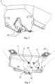
figure 5 shows a further sectional view of a detail of the tank offigure 1 , with an adjustment plate removed and with a metering plate highlighted; -
figure 6 shows a front view of the metering plate offigure 5 , according to a first embodiment of the present invention; -
figure 7 shows a further front view of the metering plate offigure 6 , withe fixing holes highlighted on a lever arm; -
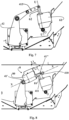
figure 8 shows a front view of the metering plate offigure 5 with adjustment means highlighted, according to a second embodiment of the present invention; -
figure 9 shows a front view of an embodiment variant of the farming machinery, object of the invention, with the metering plate and the fixing holes offigure 7 ; -
figure 10 shows a front view of the embodiment variant of the machinery offigure 9 , with the metering plate and the adjustment means offigure 8 ; -
figures 11A and 11B show a perspective view of a detail of means for distributing the ground treatment product, relative to a mixer body; -
figure 12 shows a perspective view of a further detail of means for distributing the ground treatment product, relative to a spreader plate; -
figure 13 shows a graph on which two metering curves are illustrated for a treatment product to be distributed on a terrain, relative to two first lengths of a lever arm of the metering plate. - With reference to the enclosed drawings, reference number 1 overall indicates farming machinery for distributing treatment products on the ground, in accordance with the present invention.
- In particular, the farming machinery, object of the invention, is advantageously employable for distributing different products for treating the ground, such as for example manures, fertilizers, seeds or functional additives such as poisons and fungicides.
- The abovementioned products are advantageously in solid form and can be in the form of granules, pellets etc. as described more in detail hereinbelow.
- More in detail, the present machinery 1 is intended to be employed in the farming field, and in particular in the field of cultivation of terrain, both of limited size such as vineyards and orchards, and of larger dimensions such as open fields.
- As better described hereinbelow, the machinery 1, object of the invention, is preferably machinery of electronic type, i.e. adapted to be programmed electronically in order to allow high automation of the ground working and thus increase the productivity and efficiency of the machinery itself.
- The farming machinery, object of the present invention, is indeed advantageously employable in all those contexts in which it is necessary to have a high metering precision, e.g. in the case of terrain of limited extension (e.g. vineyards or orchards in which the sowing width can also reach 2 meters), or in the event in which it is necessary to spread products with limited metering (preferably lower than 120 kg/ha such as for example poisons or fungicides) or in the event in which it is necessary or desired to move the machinery itself at limited advancing speeds (preferably lower than 8 km/h).
- The present farming machinery 1 for distributing treatment products on the ground comprises a support frame 2, preferably metallic, and at least one
tank 3, fixed to the support frame 2 and adapted to contain products to be distributed on the ground. Thetank 3 is provided with at least oneopening 31 for dispensing the products to be distributed. - In particular, the dispensing
opening 31 is preferably made on the side of thetank 3, in particular on alateral wall 33 thereof, which will be described in detail hereinbelow, even if as an alternative the dispensingopening 31 can be made on a lower bottom wall of thesame tank 3. - Advantageously, the farming machinery 1 also comprises distribution means 5, mechanically connected to the support frame 2, placed below the dispensing opening 31 of the
tank 3 and comprising at least onespreader plate 50 which is intended to receive the dose of the products from the dispensing opening 31 of thetank 3 and is actuatable in rotation in order to distribute the dose of products on the ground. - The farming machinery 1 is also provided with at least one metering plate 4, which comprises a
lever arm 41 and aclosure arm 42 fixed together, preferably made of a single body, and is mechanically pivoted to thetank 3 at a hinging point C interposed between thelever arm 41 and theclosure arm 42. More in detail hereinbelow by "hinging point" a point or a localized area will be intended, in which the metering plate 4 is hinged to thetank 3, in particular by means of a rotary or roto-translational connection element, for example in a non-limiting manner made by means of a hinge pin. - In particular, the metering plate 4 thus built is rotatably movable around such hinging point C.
- The
closure arm 42 is movable with respect to the hinging point C along a movement trajectory S. - In particular, the movement trajectory S is preferably extended along an arc of circumference with respect to the hinging point C, preferably along a arc of circumference provided with an extension comprised between 25° and 60°.
- Of course, without departing from the protective scope of the present invention, the trajectory S can be extended according to any other trajectory, e.g. a trajectory that can be approximated to a circumference arc, in particular an ellipse arc, or rectilinear.
- The
closure arm 42 is movable along the aforesaid movement trajectory S between multiple operating positions in which it is placed to at least partially close of the dispensingopening 31. More in detail, theclosure arm 42 is advantageously provided with a perimeter edge having at least oneshaped section 420 which is placed with the shapedsection 420 to at least partially close the dispensingopening 31. - In this manner the metering plate 4 can selectively open and/or close, with its
closure arm 42, the dispensingopening 31, respectively increasing or decreasing the metering of the product to be distributed. - According to the idea underlying the present invention, the machinery comprises a first
linear actuator 6, which is pivoted to thelever arm 41 and to thetank 3, preferably by means of two distinct hinging eyelets adapted to allow the mutual rotation between the firstlinear actuator 6, thelever arm 41 and thetank 3. - The first
linear actuator 6 is also provided with afirst jacket 61 and with afirst stem 62, which is extensible with respect to thefirst jacket 61 along an actuation travel U. - Advantageously, the
first stem 62 is hinged to thelever arm 41 and thefirst jacket 61 is hinged to the tank 3 (as in the examples of the enclosed figures), or vice versa. - In particular, the
lever arm 41 has a first hinging eyelet and the firstmovable stem 62 of the firstlinear actuator 6 is preferably provided with a second hinging eyelet, concentric with respect to the first eyelet. Advantageously, the firstlinear actuator 6 acts on thelever arm 41 at an actuation point A. More in detail, the firstlinear actuator 6 acts on thelever arm 41 in order to rotate themetering arm 42 around the hinging point C in two opposite rotation senses (clockwise and counterclockwise). Therefore, the firstlinear actuator 6 can act thrustingly, in order to rotate themetering arm 42 in a first rotation sense, and under traction, in order to rotate themetering arm 42 in a second rotation sense. - In particular, the first and the second hinging eyelet are advantageously connected by means of junction elements, at the actuation point A, in a manner such to allow the mutual rotation of the
lever arm 41 with respect to thefirst stem 62 of the firstlinear actuator 6 during the actuation of the same. - The
first stem 62 is extensible with respect to thefirst jacket 61 along an actuation travel U in an actuation direction Z transverse to thelever arm 41, in order to move theclosure arm 42 along the aforesaid movement trajectory S in different discrete operating positions interposed between a maximum opening position, in which the dispensingopening 31 is substantially free of the metering plate 4, and a maximum closing position, in which the dispensingopening 31 is totally covered by the metering plate 4 in order to substantially prevent the entire dispensing of the product to be distributed. Advantageously, thefirst stem 62 is movable along the aforesaid actuation direction Z, along opposite movement senses, of which a first sense determines the thrust of the firstlinear actuator 6 on the lever arm 42 (in order to rotate it in the first rotation sense), while the second sense determines the traction of the firstlinear actuator 6 on the same lever arm 42 (in order to rotate it in the second rotation sense). The ratio Q between the angular movement of theclosure arm 42 along the movement trajectory S and the actuation travel U of thefirst stem 62 of the firstlinear actuator 6 along the actuation direction Z is smaller than or equal to 0.65 °/ mm. - In this manner, farming machinery 1 is obtained that is provided with a high sensitivity in the metering of the product to be distributed. In particular, as mentioned above, following the actuation of the first
linear actuator 6 thefirst stem 62 it is moved by a minimum travel, which corresponds with a reduced rotation of the metering plate 4. - More in detail, with the expression "minimum travel" it is intended the minimum movement of the
first stem 62 following the actuation of the firstlinear actuator 6, which corresponds with the sensitivity of the same firstlinear actuator 6. - Advantageously, the first
linear actuator 6 is movable in extension and in retraction between an extended position and a extended position. - Preferably, the first
linear actuator 6 is provided with an active travel, which is smaller than the total travel of thefirst stem 62 since during an activation travel, in particular, comprised between 1 and 4 mm, in which thefirst stem 62 is moved from the retracted position, in which it is substantially totally housed in thefirst jacket 61, towards the extended position, and for a final travel, this too comprised between 1 and 4 mm, in which thefirst stem 62 is in proximity to the maximum extension thereof, there is no movement of the metering plate 4. - Therefore, for example for a travel of the
first stem 62 of 50 mm, the active travel will be comprised between 42 and 48 mm. - For the sake of description simplicity, with the term travel it will be intended the active travel of the actuator.
- Such embodiment solution is particularly advantageous in the case of use on electronic machinery, in which the first
linear actuator 6 acts on thelever arm 41 as a function of the variation of the operating conditions (e.g. as a function of the speed of the machinery 1 or of the position of the machinery on the field, in particular detected by means of a GPS). - Even if the present machinery 1 is employable in a preferred embodiment as machinery of "electronic" type, and in an alternative embodiment also as "manual" machinery, this was particularly designed for being used in its electronic configuration, in which therefore the
lever arm 41 is movable automatically also during the movement of the machinery 1 on the field. - In particular, in accordance with the preferred embodiment, the first
linear actuator 6 is an electric actuator, provided with a travel sensitivity of at least 2 mm and preferably of about 0.5 mm. - Of course, without departing from the protective scope of the present invention, the first
linear actuator 6 can be of hydraulic, pneumatic or mechanical type and preferably provided with the same travel sensitivity of the abovementioned electric actuator. - Therefore, in accordance with the aforesaid preferred embodiment, the
first stem 62 of the firstlinear actuator 6 acts along the actuation direction Z for a minimum travel equal to 0.5 mm, determining a rotation of the metering plate 4 smaller than or equal to 0.3°. - In particular, in the event in which the arc of circumference of the movement trajectory S is extended between 25° and 35°, hence a minimum travel of the
first stem 62 corresponds with a movement of the metering plate 4 equal to about 0.4% with respect to the complete arc of circumference that the latter can complete along the movement trajectory S. - Preferably, such ratio is independently met by the position of the metering plate 4 along the movement trajectory S, i.e. by the percentage of dispensing
opening 31 already covered. In this manner therefore, even in the case of low metering, i.e. in proximity to the maximum closed position, it is possible to precisely adjust the metering of the product to be distributed. - Advantageously, the ratio between the angular movement of the
closure arm 42 and the actuation travel U of thefirst stem 62 is obtained by means of a specific ratio between the length of theclosure arm 42 and the active length of thelever arm 41, described more in detail hereinbelow. - Advantageously, the "active"
lever arm 41, intended as the section oflever arm 41 interposed between the hinging point C and the actuation point A, is relatively long with respect to the length of theclosure arm 42. - More in detail, the
lever arm 41 is extended along a first extension direction X, between a first end 41', placed at the hinging point C and an oppositesecond end 41". - In particular, the
lever arm 41 is provided with an active section provided with a first length D1, measured between the first end 41' thereof (advantageously coinciding with the hinging point C) and the actuation point A in which thefirst stem 62 of the firstlinear actuator 6 is hinged, which preferably is placed at thesecond end 41" of thelever arm 41. - In particular, the first
linear actuator 6 is pivoted to thelever arm 41 at thesecond end 41" of the latter in order to exploit the maximum extension of thelever arm 41 itself, however, as explained more in detail hereinbelow, the firstlinear actuator 6 can also act at an intermediate point along the first extension direction X. - Advantageously, the
closure arm 42 is extended along a second extension direction Y, for a second length D2, between a third end 42' placed at the hinging point C and afourth end 42" opposite the third end 42'. - In particular, the ratio between the first length D1 and the second length D2 is preferably comprised between 1.5 and 0.45, so as to determine a small angular movement of the
closure arm 42 given the same movement of thefirst stem 62 along the actuation direction Z. - Preferably, the ratio between the first length D1 and the second length D2 is comprised between 0.95 and 0.45, in a manner such that the metering plate 4 is advantageously a class 1 lever of advantageous or indifferent type, in which the power arm, constituted by the
lever arm 41, is shorter or at most equal to the resistance arm, constituted by theclosure arm 42. - Nevertheless, in an embodiment variant of the present invention, as described more in detail hereinbelow, the
lever arm 41 is extensible, and the first length D1 increases in a manner such that the ratio between the first length D1 and the second length D2 also reaches values comprised between 0.95 and 1.5. - Advantageously, the first extension direction X and the second extension direction Y hit each other and together form a first angle α comprised between 100° and 130°.
- Of course the width of the first angle α is expressed in absolute value and therefore the first angle α can be extended according to a clockwise or counterclockwise rotation sense depending on the design needs of the machinery 1.
- Such width of the first angle α allows positioning the
lever arm 41 and theclosure arm 42 with respect to each other to partially delimit an operative zone, within which it is possible to easily obtain the trajectory S and position the dispensingopening 31. - Indeed if the first angle α is smaller than 100°, the first
linear actuator 6 would be hard to position since it would risk being superimposed on the dispensingopening 31; otherwise, if the first angle α is greater than 130°, alateral wall 33 of thetank 3 would be necessary with large size, since theclosure arm 42 and thelever arm 41 would be nearly aligned with each other along the extension directions X, Y. Advantageously, the ratio between the actuation travel U of the firstlinear actuator 6 and the first length D1 of the active section of thelever arm 41 is comprised between 0.45 and 0.6. - Such ratio allows the
lever arm 41 to transfer a rotation to theclosure arm 42 such to cover the entire trajectory S. It is in fact clear that by lowering the sensitivity of the rotation of theclosure arm 42 by means of an elongation of thelever arm 41, one must at any rate ensure an actuation travel U sufficiently long such to cover the entire rotation of theclosure arm 42. - For example, for a trajectory S of 45° width, if the ratio Q is lowered by 3 °/mm to 1 °/mm, the actuation travel U of the
first stem 62 of the firstlinear actuator 6 must be tripled. - Advantageously, it is also possible to obtain the ratio between the angular movement of the
closure arm 42 and the actuation travel U of thefirst stem 62 of the firstlinear actuator 6 by means of the arrangement of the firstlinear actuator 6 with a tilt with respect to the first extension direction X such to minimize the force exerted on thelever arm 41, given the same discrete movement of thefirst stem 62 along the actuation travel U, e.g. 0.5 mm. - In particular, the actuation direction Z and the first extension direction X are advantageously incident on each other at the
second end 41" and form a second angle β preferably comprised between 90° and 130°. - More in detail, in such case the second angle β is measured with the
first stem 62 in the retracted position, where it is substantially entirely contained in thefirst jacket 61. Indeed, as thefirst stem 62 progressively slides along the actuation travel U, the angle β is reduced. - In particular, with the
first stem 62 in the retracted position, theclosure arm 42 is situated in the maximum opening position, and hence the second angle β is measured with theclosure arm 42 in the aforesaid maximum opening position. - In such a manner, the orthogonal component of the movement of the
first stem 62 is reduced with respect to thelever arm 41, determining that - given the same movement of the first stem 62 - the metering plate 4 rotates by a smaller angle. - In particular, the first
linear actuator 6 exerts, by means of thestem 6, a thrust force Fs on thelever arm 41 which is in a per se known manner broken down into an orthogonal component Fsa, which determines the movement of the latter, and a parallel component Fsb which does not determine any movement of thelever arm 41. - More in detail, the component of the thrust force Fsa can be calculated by means of the following formula: Fsa = sen (β) * Fs and therefore depends on the angle β between the actuation direction Z and the first extension direction X.
- Advantageously, the first
linear actuator 6 is hinged to thelever arm 41 at the actuation point A, and the actuation point A is movable along the first extension direction X between at least two positions, in order to vary the first length D1 of the active section of thelever arm 41. - More in detail, with the term "movable" it is intended that the actuation point A can be moved and positioned in at least two different positions.
- Of course, as set forth above, the first length D1 will be variable in a manner such that the ratio between the first length D1 itself and the second length D2 is always comprised between 1.5 and 0.45. In this manner it is also possible to vary the tilt of the actuation direction Z such to adjust the component of the thrust force Fsa, since such actuation direction Z passes through the actuation point A.
- On the contrary, since the
first stem 62 is coupled to thecoupling hole 415 closest to thesecond end 41" of thelever arm 41, the first length D1 is maximized and the precision of the movement of the metering plate 4 will be greater than a first smaller length D1, given the same second angle β. - According to a first embodiment of the present invention, illustrated in
figures 7 and9 , relative to two different embodiments of the aforesaid embodiment, thelever arm 41 is provided with at least twocoupling holes 415 placed along the first extension direction X, and the firstlinear actuator 6 comprises coupling means for selectively coupling thefirst stem 62 of the firstlinear actuator 6 to one of the at least two coupling holes 415. Advantageously, in addition, the actuation point A is defined by thecoupling hole 415 with which thefirst stem 62 of the firstlinear actuator 6 is coupled by means of the coupling means. - In particular, the actuation point A is advantageously movable between at least one retracted position, in which the actuation point A and the hinging point C are placed at a first distance L1 and to which a first metering curve C1 corresponds, and at least one extended position, in which the actuation point A and the hinging point C are placed at a second distance L2, greater than the first distance L1, and to which a second metering curve C2 corresponds.
- Advantageously, the coupling means advantageously comprise the eyelets described above, together with the junction elements.
- In operation, a user can vary the first length D1 of the active section by manually coupling and releasing the eyelet of the
first stem 62 of the firstlinear actuator 6 at one of the coupling holes 415 in order to vary the closure sensitivity of the metering plate 4 along the movement trajectory S. In particular, hereinbelow by closure sensitivity it will be intended the smaller number of degrees traveled by the metering plate 4 along the movement trajectory S corresponding to a minimum movement (sensitivity) of thefirst stem 62 of the firstlinear actuator 6 along the actuation travel U thereof. - For example, by coupling the
first stem 62 with one of the coupling holes 415 in order to shorten the first length D1 of the active section of thelever arm 41, one obtains lower closure sensitivity of the metering plate 4, however the second angle β increases and therefore the force exerted by thelinear actuator 6 is smaller. In this manner, it is possible to maintain a good control of the metering of the treatment product also by shortening the first active length D1 of thelever arm 41. - Advantageously, the farming machinery 1 comprises at least one distance sensor (not depicted in the enclosed figures), preferably placed on the
lever arm 41 and arranged for identifying the position of the actuation point A along the first extension direction X and generating a position signal. In particular, the distance sensor identifies on whichcoupling hole 415 thefirst stem 62 is coupled. - Advantageously, the farming machinery 1 comprises multiple distance sensors, each of which arranged for monitoring a specific pair of
coupling holes 415 that are adjacent to each other. - Advantageously, in addition, the farming machinery 1 comprises a logic control unit, in data communication with the distance sensor and configured for driving the first
linear actuator 6 to actuate thelever arm 41 in order to move theclosure arm 42 along the movement trajectory S and adjust the opening of the dispensingopening 31 on the basis of the position signal of the distance sensor. - In particular, based on the generated position signal, the logic control unit will select a specific metering curve between at least the two metering curves C1, C2.
- According to a second embodiment of the present invention, illustrated in
figures 8 and10 , which show two different embodiments of the aforesaid second embodiment, the metering plate 4 is not directly pivoted to thetank 3, but to an intermediate element, which is fixed on thetank 3, in particular abutted against alateral wall 33 of the latter. - Advantageously, in accordance with such second embodiment, also the first
linear actuator 6 is pivoted to the tank by means of the aforesaid intermediate element, as is visible infigures 9 and 10 . - In addition, according to the aforesaid second embodiment of
figures 8 and10 , thelever arm 41 advantageously comprises a main portion 410 (in particular, fixed with respect to the metering plate 4), and anextensible portion 411, on which the actuation point A is made and which is slidably connected to themain portion 410 along the first extension direction X. - In particular, the
main portion 410 is provided with the first end 41' of thelever arm 41 and theextensible portion 411 is provided with thesecond end 41". - Advantageously in addition, the machinery 1 comprises adjustment means, mechanically connected and interposed between the
main portion 410 and theextensible portion 411 of thelever arm 41 and susceptible of acting on theextensible portion 411 in order to vary the position thereof along the first extension direction X with respect to themain portion 410. - Advantageously, the
extensible portion 411 is movable between at least one retracted position, in which the actuation point A and the hinging point C are placed at a first distance L1 and to which a first metering curve C1 corresponds and at least one extended position, in which the actuation point A and the hinging point C are placed at a second distance L2, greater than the first distance L1, and to which a second metering curve C2 corresponds. - Of course, the
extensible portion 411 can be adjusted at multiple intermediate positions, in which the actuation point A and the hinging point C are placed at a distance comprised between the first distance L1 and the second distance L2. - According to a first embodiment solution of the second embodiment of the present invention, the adjustment means comprise a second
linear actuator 8, and theextensible portion 411 is movable along the first extension direction X by means of the secondlinear actuator 8 between the retracted position and the extended position. - Preferably, the second
linear actuator 8 is provided with asecond jacket 80 mounted outside themain portion 410 of thelever arm 41, and asecond stem 81, movable between the retracted position and the extended position. Advantageously, thesecond stem 81 constitutes theextensible portion 411. However, without departing from the protective scope of the present invention, theextensible portion 411 can be mechanically connected to thesecond stem 81 of the secondlinear actuator 8 and be moved by the latter between the retracted position and the extended position. - Advantageously, the
main portion 410 is constituted by a metal plate fixed to thetank 3 at the hinging point C and preferably made in a single body with theclosure arm 41. Advantageously, themain portion 410 is provided with at least one first rail, extended along the first extension direction X and on which theguide portion 411 is slidably engaged. - Advantageously, the junction elements of the first and second eyelet of the first
linear actuator 6 are placed on theguide portion 411 in order to slide in a guided manner on the first rail following the actuation of the secondlinear actuator 8. - In this manner it is possible to precisely and automatically adjust the first length D1 of the
lever arm 41, without varying the first angle α. - In particular, still according to the present embodiment solution, the second
linear actuator 8 is capable of moving the firstlinear actuator 6, in particular the actuation point A, along an adjustment trajectory V, between at least the retracted position, in which the actuation direction Z is tilted with respect to a vertical direction, and an extended position, in which the actuation direction Z is substantially vertical. Advantageously in addition, during the movement of the actuation point A along the adjustment trajectory V by means of the secondlinear actuator 8 from the retracted position to the extended position, the second angle β remains comprised within the above-reported interval. - In this manner, farming machinery 1 is obtained for distributing products on the ground in a highly precise and reproducible manner, also in the case of large-
size dispensing openings 31, in which the adjustment of the flow occurs with limited bulk. - According to a second embodiment solution of the second embodiment, the adjustment means advantageously comprise a guide provided with at least one second rail, mechanically fixed to a
lateral wall 33 of thetank 3. Advantageously, theextensible portion 411 is slidably mounted on the second rail and is manually adjustable by a user before actuating the farming machinery 1. Preferably, the adjustment means comprise quick fixing elements of theextensible portion 411 in extended, retracted position or in an intermediate position between the two, in a manner such to define a metering curve based on which the firstlinear actuator 6 adjusts the opening of the metering plate 4 during the treatment. - In a manner entirely analogous to the first embodiment, the machinery can also in this case comprise the distance sensor, and based on the generated position signal, the logic control unit will select the correct metering curve.
- Advantageously, in a manner common to the first and to the second embodiment, the farming machinery 1 comprises at least one
adjustment plate 7, which is interposed between the metering plate 4 and thetank 3, is mechanically connected to the latter, is provided with at least one first throughopening 71 and at least one second through opening 72 and theadjustment plate 7 is movable between at least one first position, in which the first throughopening 71 is placed at the dispensingopening 31 of thetank 3 and the metering plate 4 is placed to at least partially close the first throughopening 71, and a second position, in which the second through opening 72 is placed at the dispensingopening 31 of thetank 3, and the metering plate 4 is placed to at least partially close the second throughopening 72. - In particular, when the first through
opening 71 is placed at the dispensingopening 31 of thetank 3, the second through opening 72 is placed against thelateral wall 33 of thetank 3 so as to be closed and thus prevent the passage of product to be distributed. - In the same manner, when the second through opening 72 is placed at the dispensing
opening 31 of thetank 3 the first throughopening 71 is placed against thelateral wall 33 of thetank 3 so as to be closed and thus prevent the passage of product to be distributed. - Advantageously, the dispensing
opening 31 has an irregular parallelepiped shape, and is advantageously delimited by a base section, preferably rectilinear and by twooblique sides 310 which define a substantially trapezoidal lower portion on the dispensingopening 31. In addition, advantageously, the dispensingopening 31 is delimited on the upper part by an irregular edge, substantially curvilinear, which defines an irregular upper portion on the dispensingopening 31, preferably provided with an extension greater than the trapezoidal lower portion. - Preferably, the first through
opening 71 is counter-shaped with respect to the dispensingopening 31, and the second through opening 72 is provided with an extension smaller than the first throughopening 71. - The farming machinery 1 then allows selecting a different metering curve as a function of the different operating conditions.
- More in detail, each through opening corresponds with a different metering curve, where hereinbelow with the expression "metering curve" it will be intended a function that allows describing a function which allows describing the dependence of the flow rate (e.g. expressed in grams per second) of the product to be distributed as a function of the movement (e.g. expressed in mm) of the metering plate 4 along the movement trajectory S.
- In particular, the first through
opening 71 is associated with a third metering curve while the second throughcurve 72 is associated with a fourth metering curve. - Preferably, the first through
opening 71 and the second through opening 72 are shaped in a manner such that the third metering curve and the fourth metering curve are associable with a line. - In accordance with the preferred embodiment in which the first through
opening 71 is provided with a passage section greater than the passage section of the second through opening 72, the third metering curve is provided with a greater angular coefficient (being steeper). This involves a lower sensitivity of the flow of product dispensed as a function of the movement of the metering plate 4, which allows obtaining a more precise adjustment of the flow of product dispensed upon variation of the movement of the metering plate 4 itself between the different operating positions. - For example, with a movement of the
stem 62 of the firstlinear actuator 6 by a minimum travel of 1 mm along the actuation travel U, the increase or the decrease of flow will be greater for the third metering curve than the fourth metering curve (with "more horizontal" progression), given the same starting position along the actuation travel U. - Advantageously, the second metering curve is particularly advantageous in the case of reduced product flow rates, e.g. comprised between 20 g/s and 400 g/s.
- In this manner, according to the second embodiment solution of the second embodiment of the present invention, if the first through
opening 71 is selected, the secondlinear actuator 8 advantageously acts on the actuation point A, preferably translating it into extended position. Consequently, thelever arm 41 will be extended up to reaching the maximum extension, obtaining a ratio between the actuation travel U and the first length D1 comprised in the intervals described in the first embodiment. - In this manner, a combination of the advantages described up to now is obtained: on one hand, the orthogonal thrust component of the
first stem 62 on thelever arm 41 is limited, on the other hand the angular movement is limited given the same travel of thefirst stem 62. - Of course, if the second through opening 72 is selected, depending on the dose of product to be dispensed and on the plurality of operating parameters better described hereinbelow, the second
linear actuator 8 advantageously acts on the actuation point A (and consequently on the first length D1 of the lever arm 41) in order to optimize the ratio between the increase of flow dispensed following the opening of the metering plate 4, in relation to the travel of thefirst stem 62 of the firstlinear actuator 6. In this manner it is also possible to obtain a plurality of metering curves, since for a same throughopening first stem 62 of the firstlinear actuator 6, the metering plate 4 can be moved with more or less sensitivity, based on the width of the second angle β and of the first length D1. - In particular, the number of selectable metering curves is proportional to the sensitivity of the travel of the second
linear actuator 8. For example, a movement of the actuation point A along the adjustment trajectory V of 1 mm, will correspond with a variation of 1° of the second angle β. - Of course, without departing from the protective scope of the present invention, the first
linear actuator 6 and the secondlinear actuator 8 can also be employed according to different operating modes with respect to that described above. - For example, the first
linear actuator 6 is employable in order to fix an objective flow, by setting a fixed position of thefirst stem 62 along the actuation travel U and therefore defining an initial second angle β, which corresponds with a specific degree of opening of the dispensingopening 31. - In operation, depending on the speed of the farming machinery 1 or on the needs of the operator during the dispensing of the product on the ground, the second
linear actuator 8 can be employed for adjusting the opening of the metering plate 4 along the movement trajectory S, by varying the first active length D1 of thelever arm 41. More in detail, the secondlinear actuator 8 acts thrustingly against the junction elements of the two eyelets, which slide along the first rail, by slightly rotating the metering plate 4 since, as set forth above, the travel of thefirst stem 62 of the firstlinear actuator 6 is fixed to the starting position. - In other words, the metering curve is defined by the combination of the initial position of the
first stem 62 and of theadjustment plate 7, and the movement along the metering curve occurs by means of the actuation of the secondlinear actuator 8. - Analogously, it is possible to advantageously firstly fix the first length of the
lever arm 41 by means of the second linear actuator 8 (or, according to the first embodiment variant by means of the manual movement on acoupling hole 415 or along the rail on which the extensible portion of thelever arm 41 slides), and execute a fine adjustment on the position of the metering plate 4 by means of the actuation of the firstlinear actuator 6. - Advantageously, the farming machinery 1 comprises a third linear actuator, preferably of electric type, mechanically connected to the
adjustment plate 7 in order to move the latter between the first position and the second position. - In accordance with the aforesaid preferred embodiment, the
adjustment plate 7 is advantageously provided, preferably in a single body, with an adjustment arm 70 actuatable for moving theadjustment plate 7 between the first and the second position. - Advantageously, the third linear actuator is advantageously fixed to the adjustment arm 70 such to actuate it in an automated manner in order to move the
adjustment plate 7 between the aforesaid first and second position. - Advantageously, the farming machinery 1 is a machinery of electronic type, i.e. preferably drivable in an automatic manner by an operator directly from the cabin by means of a user interface (or alternatively by means of a dedication application remotely connected to the machinery), as better explained hereinbelow.
- Advantageously, the farming machinery 1 provides that at least the
lever arm 41 is moved also during the operation of the machinery itself, so as to repeatedly adjust the position thereof as a function of the variation of the operating parameters (such as for example the advancing speed of the farming machinery, the work width, the specific dispensing flow rate per unit of surface). - Advantageously, as set forth above, according to the first embodiment of the present invention, the farming machinery 1 comprises a logic control unit electrically connected to at least the first
linear actuator 6, and is configured for driving the firstlinear actuator 6 to actuate thelever arm 41 and in order to move theclosure arm 42 along the movement trajectory S and adjust the opening of the dispensingopening 31. - Advantageously in addition, according to the second embodiment of the present invention the logic control unit is also electrically connected to the second
linear actuator 8 and is configured for driving the secondlinear actuator 8 to move theextensible portion 411 of thelever arm 41 in order to set one between the first metering curve C1 and the second metering curve C2, and to the third linear actuator, in order to adjust the actuation point A or theadjustment plate 7. - In particular, the logic control unit comprises a control panel, preferably installed in a cabin of the farming machinery 1 and configured for allowing a user to select and set the operating position of the
closure arm 42 and one between the first position and the second position of theadjustment plate 7. More in detail, by means of the aforesaid control panel the user sets such positions and the logic control unit sends a corresponding electrical signal to the firstlinear actuator 6, to the secondlinear actuator 8 and to the third linear actuator to actuate the latter to respectively move thelever arm 41, the actuation point A and theadjustment plate 7 in order to place them in the desired positions. - In particular, according to the embodiment in which the
containment tank 3 is provided with two dispensingopenings 31 and with two metering plates 4, the logic control unit is arranged for driving the firstlinear actuators 6 which adjust the opening of the different metering plates 4 in a manner independent of each other, in this manner enabling the simultaneous distribution of two different quantities of product through the two dispensingopenings 31 on a same ground or the working of two different terrains that are adjacent to each other. - In particular, according to the aforesaid embodiment it is possible to load one or more product metering prescription maps and configure the logic control unit so that it actuates the first
linear actuators 6 connected to the two metering plates 4 according to the aforesaid prescription maps. - Advantageously, the logic control unit can also comprise a calculation unit and a memory unit, within the which a series of metering programs are stored comprising for example one or more of the aforesaid prescription maps.
- Advantageously, each metering program corresponds with a set of data comprising at least one angular position of the closure plate 4 and a position of the
adjustment plate 7, which depend on the particular product to be distributed (and its physical-chemical characteristics) and on a series of operating parameters such as for example the width and the type of ground to be treated and the speed of the farming machinery 1. - More in detail, the logic control unit is configured for allowing the user to set the product to be distributed and the aforesaid operating parameters by means of the control panel and the calculation unit is configured for calculating and selecting, based on the inserted data, the correct metering program from among those stored in the memory unit.
- The logic control unit is finally configured in order to set the corresponding positions of the closure plate 4 and of the
adjustment plate 7 of the corresponding metering program and actuate the correspondinglinear actuators lever arm 41 and the adjustment arm 70 in order to place them in the desired positions. - According to a first embodiment variant of the present invention, the adjustment arm 70 is movable manually.
- According to a second alternative embodiment variant of the present invention, the third linear actuator which moves the adjustment arm 70 is a hydraulic actuator.
- According to the aforesaid embodiment variants, the farming machinery 1 advantageously comprises a proximity sensor, which is preferably placed at the adjustment arm 70 in order to detect position of the latter and, consequently, in order to detect which of the two through
openings adjustment plate 7 is selected. - Of course, without departing from the protective scope of the present invention, the proximity sensor can be placed in any position which allows detecting the difference of positioning of the through
openings opening 31. - Such proximity sensor is advantageously connected in data communication with the logic control unit, in a manner such that, in case of manual movement of the adjustment arm 70, e.g. in case of maintenance (or in manual adjustment mode of the adjustment plate), the logic control unit is capable of identifying which through
opening opening 31 and communicating it to the, e.g. by means of a visible signal on the control panel. - Advantageously, the logic control unit is also arranged for adjusting the travel of the
linear actuators - More in detail, the logic control unit is also arranged for setting the first or the second metering curve based on the position signal received by the proximity sensor, and the travel of the first
linear actuator 6 will depend on such curve. - Of course, as stated above, the logic control unit can adjust the first
linear actuator 6 and the secondlinear actuator 8 in order to move the metering plate 4 even in the absence of theadjustment plate 7. Advantageously, the farming machinery 1 comprises aguide plate 43, fixed to thetank 3 and interposed between thetank 3 and theadjustment plate 7. - Advantageously, the
guide plate 43 is provided with an opening counter-shaped to the first throughopening 71 and theguide plate 43 is mechanically fixed to thetank 3 in a manner such that the aforesaid opening is superimposed on the dispensingopening 31. - Advantageously, the
guide plate 43 is provided with a guide surface along which theclosure arm 41 is susceptible of sliding during its movement along the trajectory S, and preferably also theadjustment plate 7 is susceptible of sliding during its movement between the first and the second position. - Advantageously, the
guide plate 43 comprises a fixingwall 431, which is parallel to thelateral wall 33 of thetank 3 and is fixed in abutment against the the latter, aslide wall 432, which is orthogonal to the fixing wall and defines the aforesaid guide surface, and, preferably, aretention wall 430, substantially parallel to the fixingwall 431 and defining, with theslide wall 432 and the fixingwall 431, a slide channel along which the metering plate 4 and preferably also theadjustment plate 7 slides. Advantageously, the guide surface of theguide plate 43 defines a slide channel, which is provided with aretention wall 430, which cooperates with a portion of theclosure arm 42 in order to retain the latter adjacent to the dispensingopening 31. In this manner it is possible to prevent the weight exerted by the treatment product from thetank 3 interior from moving theclosure arm 42 away from theguide plate 43 and allowing the product to leak through zones of the dispensingopening 31 that would normally be covered. - In accordance with the preferred embodiment, and as stated above, the
closure arm 42 is pivoted to thetank 3, preferably to the samelateral wall 33, around the hinging point C, and is rotatably connected to the latter around a rotation axis R. - Of course, in accordance with the aforesaid embodiment, also the
slide wall 432 and the slide channel of theguide plate 43 are counter-shaped with respect to the trajectory S, and in particular are extended circumferentially with respect to the hinging point C. - In accordance with the preferred embodiment illustrated in
figure 4 , theadjustment plate 7 is pivoted to thetank 3, preferably to the samelateral wall 33, around the hinging point C. - In this manner the
adjustment plate 7 is advantageously rotatably connected to thetank 3 around the same first rotation axis R and is movable along a movement direction thereof circumferential with respect to the hinging point C, preferably along an arc of circumference between the first position and the second position. - Advantageously, the
tank 3 is extended with an overturned pyramidal frustoconical shape, in particular tapered between an upper end thereof and an opposite lower end. - Preferably, the
tank 3 comprises two containing portions, preferably made in a single body, which are side-by-side each other and preferably symmetrical. - In particular, each containing portion is provided with an overturned pyramidal frustoconical shape and is extended between a first lateral wall 33' and a second
lateral wall 33", opposite and tilted with respect to the first lateral wall 33'. More in detail, the two containing portions are placed side-by-side each other with the respective secondlateral walls 33" facing and in particular which are connected at a commonupper edge 34 thereof, which is placed within the containment volume of thetank 3, as is visible infigure 2 . - Preferably, the two second
lateral walls 33" are provided with a height lower than the first lateral walls 33' such that thetank 3 is provided with a containment volume which is extended between a common upper portion and two separate lower portions, one for each containing portion. - In accordance with such embodiment the
tank 3 is provided with twoseparate dispensing openings 31, one for each containing portion, which is preferably made on corresponding secondlateral walls 33". - In particular, the
tank 3 is preferably provided with aright dispensing opening 31 and an oppositeleft dispensing opening 31, which are preferably made on corresponding secondlateral walls 33" of thetank 3. In the same manner, the distribution means 5 advantageously comprise twodistinct spreader plates 50, each of which placed below a corresponding containing portion. - Of course, without departing from the protective scope of the present invention, the dispensing
opening 31 can be made on any other wall of thetank 3, such as for example the bottom of the portions of thetank 3 or the first lateral walls 33'. - In the event in which the dispensing
opening 31 is placed on the bottom of thetank 3, thetank 3 advantageously comprises a tank body and a bottom plate, preferably made of stainless steel, mechanically fixed to the bottom wall of the tank body. - Advantageously, the metering plate 4, the first
linear actuator 6 and, if present, also the secondlinear actuator 8 and theadjustment plate 7 and the third linear actuator, are fixed to the bottom plate. - In such case, consequently, also the metering plate 4 and the
adjustment plate 7 will be placed respectively on the bottom of the portions of thetank 3 or on the first lateral walls 33', in order to allow an adjustment of the effective flow independent of the position of the dispensingopening 31. - Of course in accordance with such embodiment the farming machinery 1 is also provided with two metering plates 4 and two
adjustment plates 7, fixed to corresponding containing portions, so as to allow the precise and regulated metering of the product to be distributed from both containing portions of thetank 3. - Preferably, in accordance with such embodiment, the machinery 1 is provided with two first
linear actuators 6 and (optionally) with two secondlinear actuators 8, each of which mechanically connected to a corresponding metering plate 4 in order to move it along the corresponding movement trajectory S. Advantageously, the firstlinear actuators 6 and (possibly) the secondlinear actuators 8 are independent of each other and, are differently actuatable in order to allow different dispensing from theright dispensing opening 31 and from theleft dispensing opening 31 of the two containing portions of thetank 3. - In such case, consequently, also the
lever arm 41 and theclosure arm 42 will be respectively placed on the bottom of the portions of thetank 3 or on the first lateral walls 33', in order to allow an effective adjustment of the flow independent of the position of the dispensingopening 31. - Of course in accordance with such embodiment the closure means 4 are also provided with two
lever arms 41 and twoclosure arms 42, fixed to corresponding containing portions, so as to allow the precise and adjusted metering of the product to be distributed from both the containing portions of thetank 3. Advantageously thetank 3 comprises at least one housing hole, and preferably a housing hole for each containing portion, which is made passing through the lower wall of thetank 3. - As set forth above, the farming machinery 1 comprises distribution means 5 provided with a
spreader plate 50, which are well known to the man skilled in the art and therefore will not be described in detail. More in detail, thespreader plate 50 is provided with at least onespreader blade 501, and preferably twospreader blades 501, fixed on an upper face of thespreader plate 50, directed towards the dispensingopening 31, and in particular thespreader blades 501 are extended from the center of thespreader plate 50 in opposite directions, up to a peripheral edge of thespreader plate 50 itself or projecting towards the exterior from the edge of thespreader plate 50. - Advantageously, the distribution means 5 also comprise at least one
mixer body 51, placed within thetank 3 and comprising apin 510, rotatably housed, preferably to size by means of suitable bearings, within a corresponding housing hole. - The
pin 510 is fixed to thespreader plate 50 in order to be moved together with the latter, which is for example, in a per se known manner, moved by means of the power take-off placed to connect between thetank 3 and the drive motor of the machinery 1. - The
pin 510 advantageously comprises, at an upper end thereof, anenlarged plate 511 from which at least onetab 512 is projectingly extended, intended to convey the product to be dispensed towards the dispensingopening 31 during its movement imparted by thespreader plate 50. - Of course, without departing from the protective scope of the present invention, the
enlarged plate 511 can lack theaforesaid tab 512, depending on the type of product to be distributed; for example in order to distribute fragile products such as seeds the enlarged plate will lack the tab 512). - Advantageously, the machinery 1 comprises a GPS device mounted on the support frame 2, electrically connected in data communication with the logic control unit.
- More in detail, the GPS device is arranged for detecting the position of the machinery 1 along the path to be completed during working and for sending, to the logic control unit, a corresponding position signal, representative of the position of the farming machinery 1.
- Advantageously, the logic control unit is arranged for receiving the aforesaid position signal and actuating the first
linear actuator 6 and/or the secondlinear actuator 8 in order to correct the flow of products dispensed through the dispensingopening 31 based on the position of the farming machinery 1. - In addition, the machinery 1 advantageously comprises at least one load cell, electrically connected in data communication with the logic control unit and mechanically fixed between the support frame 2 and the connection structure to the drive motor so as to allow calculating, preferably continuously, due to an automatic filtering, the weight of the product within the
containment tank 3, as well as its physical flow characteristics. - More in detail, the load cell is advantageously arranged for generating a flow signal, representative of the flow of products dispensed by the dispensing
opening 31, and sending the aforesaid flow signal to the logic control unit. - For example, the aforesaid flow signal is generated based on the continuous calculation of the weight difference of the product contained within the
containment tank 3. - Advantageously, the logic control unit is arranged for receiving the aforesaid flow signal and actuating the first
linear actuator 6 and/or the secondlinear actuator 8 in order to correct the flow of products dispensed through the dispensingopening 31. - In this manner, the logic control unit to which the load cell is connected measures the quantity of product exiting from the
containment tank 3 and is capable of verifying and if necessary adjusting the metering automatically, in particular by modifying the position of the metering plate 4 by means of one of thelinear actuators - In particular, in the event in which the load cell detects a flow lower than the objective flow, the logic control unit would command one of the
linear actuators opening 31. - On the contrary, in the event in which the load cell detected a flow greater than the objective flow, the logic control unit would command the first
linear actuator 6 and/or the secondlinear actuator 8 to move the metering plate 4 to partially close the dispensingopening 31 and correct the flow of products dispensed by the dispensingopening 31 itself. - In particular, the weighing cells, due to the aforesaid automatic filtering, calculate the different fertilizer flow characteristics with maximum precision and reliability even during movement.
- In addition, the machinery 1 described herein can be provided with the ISOBUS technology, i.e. with a technological communication standard that is based on the standard ISO 11783, due to which with only one display all of the compatible ISOBUS tools are driven from the cabin, such tools connected to the display.
- Due to such characteristic, the machinery 1, object of the invention, is able to automatically manage, for example by means of prescription maps, the dose of product to be distributed on the ground.
- In addition, as set forth above, the fertilizer spreader, object of the invention, allows automatically adjusting the opening of the metering plate 4 as a function of the advancing speed of the machinery 1 (DPAE), which can be detected by means of the GPS device or detection directly from the kilometer counter of the drive motor, and as a function of the actual flow characteristics of the products used in fertilization.
- Therefore, even if changing the advancing speed, the pre-selected dose remains substantially constant. The invention thus conceived therefore attains the pre-established objects.
Claims (11)
- Farming machinery for distributing treatment products on the ground, which comprises:- a support frame (2);- at least one tank (3), fixed to said support frame (2) and adapted to contain products to be distributed on the ground, said tank (3) being provided with at least one opening (31) for dispensing said products to be distributed;- at least one metering plate (4), which comprises a lever arm (41) and a closure arm (42) fixed together and is mechanically pivoted to said tank (3) at a hinging point (C) interposed between said lever arm (41) and said closure arm (42);said closure arm (42) being movable with respect to said hinging point (C) along a movement trajectory (S) between multiple operating positions in which it is placed to at least partially close said dispensing opening (31);said machinery being characterized in that it comprises at least one first linear actuator (6) which is pivoted to said lever arm (41) and to said tank (3), and is provided with a first jacket (61) and with a first stem (62), which is extensible with respect to said first jacket (61) along an actuation travel (U) in an actuation direction (Z) transverse to said lever arm (41), in order to move said closure arm (42) along said movement trajectory (S);the ratio (Q) between the angular movement of said closure arm (42) along said movement trajectory (S) and the actuation travel (U) of the first stem (62) of said first linear actuator (6) along said actuation direction (Z) being smaller than 0.65 °/mm.
- Machinery according to claim 1, characterized in that the first stem (62) of said first linear actuator (6) acts along said actuation direction (Z) for a minimum travel equal to 0.5 mm, determining a rotation of said metering plate (4) smaller than or equal to 0.3°.
- Machinery according to claim 1 or 2, characterized in that:- said first linear actuator (6) acts on said lever arm (41) at an actuation point (A);- said lever arm (41) is extended along a first extension direction (X), between a first end (41'), placed at said hinging point (C) and a second opposite end (41");
said lever arm (41) being provided with an active section, having a first length (D1), measured between the first end (41') thereof and the actuation point (A);- said closure arm (42) is extended along a second extension direction (Y), for a second length (D2), between a third end (42') placed at said hinging point (C) and a fourth end (42") opposite said third end (42').the ratio between the first length (D1) and the second length (D2) being comprised between 1.5 and 0.45. - Farming machinery according to claim 3, characterized in that said first extension direction (X) and said second extension direction (Y) hit each other and together form a first angle (α) comprised between 100° and 130°; and that
said actuation direction (Z) and said first extension direction (X) hit each other at said second end (41") and form a second angle (β) comprised between 90° and 130° with said first stem (62) in a retracted position, in which it is substantially totally housed in said first jacket (61). - Farming machinery for distributing treatment products on the ground according to claim 3 or 4, characterized in that said first linear actuator (6) is hinged to said lever arm (41) at said actuation point (A);
said actuation point (A) being movable along said first extension direction (X) between at least two positions, in order to vary the first length (D1) of the active section of said lever arm (41). - Farming machinery for distributing treatment products on the ground according to claim 5, characterized in that said lever arm (41) is provided with at least two coupling holes (415) placed along said first extension direction (X), and said first linear actuator (6) comprises coupling means for selectively coupling the stem (62) of said first linear actuator (6) to one of said at least two coupling holes (415);
said actuation point (A) being defined by the coupling hole (415) with which the stem (62) of said first linear actuator (6) is connected by means of said coupling means, and being movable between:- at least one retracted position, in which said actuation point (A) and said hinging point (C) are placed at a first distance (L1) and with which a first metering curve (C1) corresponds; and- at least one extended position, in which said actuation point (A) and said hinging point (C) are placed at a second distance (L2), greater than said first distance (L1), and with which a second metering curve (C2) corresponds. - Farming machinery for distributing treatment products on the ground according to claim 5, characterized in that said lever arm (41) comprises a fixed main portion (410), and an extensible portion (411), on which said actuation point (A) is obtained and which is slidably connected to said main portion (410) along said first extension direction (X);
said machinery (1) comprising adjustment means, mechanically connected and interposed between the main portion (410) and the extensible portion (411) of said lever arm (41) and susceptible of acting on said extensible portion (411) in order to vary its position along said first extension direction (X) with respect to said main portion (410), between- at least one retracted position, in which said actuation point (A) and said hinging point (C) are placed at a first distance (L1) and with which a first metering curve (C1) corresponds; and- at least one extended position, in which said actuation point (A) and said hinging point (C) are placed at a second distance (L2), greater than said first distance (L1), and with which a second metering curve (C2) corresponds. - Farming machinery for distributing treatment products on the ground according to claim 7, characterized in that said adjustment means comprise a second linear actuator (8) and said extensible portion (411) is movable by means of said second linear actuator (8) along said first extension direction (X) between said retracted position and said extended position.
- Farming machinery for distributing treatment products on the ground according to any one of the preceding claims, characterized in that it comprises two said metering plates (4), said tank (3) being provided with a right dispensing opening (31) and a left dispensing opening (31);said farming machinery (1) being provided with at least two said first linear actuators (6), each of which mechanically connected to a corresponding said metering plate (4) in order to move it along the corresponding said movement trajectory (S);in which said first linear actuators (6) are independent of each other and are differently actuatable in order to allow different dispensing from said right dispensing opening (31) and said left dispensing opening (31).
- Farming machinery for distributing treatment products on the ground according to any one of the preceding claims, characterized in that it comprises a logic control unit electrically connected to at least said first linear actuator (6) and is configured for driving said first linear actuator (6) to actuate said lever arm (41) in order to move said closure arm (42) along said movement trajectory (S) and adjust the opening of said dispensing opening (31).
- Farming machinery for distributing treatment products on the ground according to claim 10, characterized in that it comprises at least one load cell, electrically connected and in data communication with said logic control unit and arranged for generating a flow signal, representative of the flow of products dispensed by said dispensing opening (31) and sending said flow signal to said logic control unit;
said logic control unit being arranged for receiving said flow signal and actuating at least said first linear actuator (6) in order to correct the flow of products dispensed by said dispensing opening (31).
Applications Claiming Priority (1)
| Application Number | Priority Date | Filing Date | Title |
|---|---|---|---|
| IT102022000019029A IT202200019029A1 (en) | 2022-09-16 | 2022-09-16 | AGRICULTURAL MACHINE FOR DISTRIBUTING TREATMENT PRODUCTS ON THE LAND |
Publications (2)
| Publication Number | Publication Date |
|---|---|
| EP4338564A1 true EP4338564A1 (en) | 2024-03-20 |
| EP4338564B1 EP4338564B1 (en) | 2026-02-25 |
Family
ID=84362452
Family Applications (1)
| Application Number | Title | Priority Date | Filing Date |
|---|---|---|---|
| EP23197809.9A Active EP4338564B1 (en) | 2022-09-16 | 2023-09-15 | Farming machinery for distributing treatment products on the ground |
Country Status (2)
| Country | Link |
|---|---|
| EP (1) | EP4338564B1 (en) |
| IT (1) | IT202200019029A1 (en) |
Citations (3)
| Publication number | Priority date | Publication date | Assignee | Title |
|---|---|---|---|---|
| EP0327143A2 (en) | 1985-02-06 | 1989-08-09 | Amazonen-Werke H. Dreyer GmbH & Co. KG | Broadcaster |
| EP2404494A1 (en) | 2010-07-09 | 2012-01-11 | Amazonen-Werke H. Dreyer GmbH & Co. KG | Metering device |
| EP2724601A1 (en) | 2012-10-25 | 2014-04-30 | Amazonen-Werke H. Dreyer GmbH & Co. KG | Dosiereinrichtung |
Family Cites Families (1)
| Publication number | Priority date | Publication date | Assignee | Title |
|---|---|---|---|---|
| DE202017001237U1 (en) * | 2017-03-09 | 2018-03-12 | Rauch Landmaschinenfabrik Gmbh | Distributor and suitable metering device |
-
2022
- 2022-09-16 IT IT102022000019029A patent/IT202200019029A1/en unknown
-
2023
- 2023-09-15 EP EP23197809.9A patent/EP4338564B1/en active Active
Patent Citations (3)
| Publication number | Priority date | Publication date | Assignee | Title |
|---|---|---|---|---|
| EP0327143A2 (en) | 1985-02-06 | 1989-08-09 | Amazonen-Werke H. Dreyer GmbH & Co. KG | Broadcaster |
| EP2404494A1 (en) | 2010-07-09 | 2012-01-11 | Amazonen-Werke H. Dreyer GmbH & Co. KG | Metering device |
| EP2724601A1 (en) | 2012-10-25 | 2014-04-30 | Amazonen-Werke H. Dreyer GmbH & Co. KG | Dosiereinrichtung |
Also Published As
| Publication number | Publication date |
|---|---|
| EP4338564B1 (en) | 2026-02-25 |
| IT202200019029A1 (en) | 2024-03-16 |
Similar Documents
| Publication | Publication Date | Title |
|---|---|---|
| CA2704416C (en) | Depth adjustment of trailing arm furrow openers | |
| US10188027B2 (en) | Row unit with shank opener | |
| EP2430895B1 (en) | Trench opener/closer, agricultural seeding machine with such and method for planting | |
| US4867381A (en) | Broadcast spreader for pulverized materials | |
| US5301848A (en) | Electromagnetic meter for closed dispensing container | |
| US9622401B2 (en) | Meter for dispensing a granular product | |
| KR20220012627A (en) | Intelligent seeding machine | |
| US12588583B2 (en) | Agricultural machines having sectional control, and related systems and methods | |
| KR20160064984A (en) | Farm work support system | |
| US10561054B2 (en) | Wireless control system for floating row cleaner | |
| EP4415510B1 (en) | Row unit comprising a covering device and methods of planting seeds | |
| CN106105498A (en) | Organic and chemical fertilizer sows formula and furrowing type Multifunctional fertilizer applicator | |
| EP4338564B1 (en) | Farming machinery for distributing treatment products on the ground | |
| EP2893795B1 (en) | Spreader for spreading granular or micro-granular material on the ground | |
| US11963476B2 (en) | Sectional control funnel box | |
| AU2020203785A1 (en) | Fertilizer meter with motor control and method thereof | |
| EP4272532B1 (en) | Centrifulgal spreader | |
| EP3782450A1 (en) | Fertiliser machine for a grove of trees | |
| EP4079131A1 (en) | Method of distribution and distributor group of a chemical or organic product for the treatment of plants | |
| EP3571914B1 (en) | Fertilizer spreader | |
| AU2010202149A1 (en) | Depth adjustment of trailing arm furrow openers | |
| CN111436266A (en) | Walk-behind tobacco field precision fertilizer applicator | |
| EP0289095B1 (en) | A machine for spreading material | |
| EP1219154A1 (en) | A device for spreading granular and /or pulverulent material | |
| KR20250173093A (en) | Tractor's driving speed-sensitive fertilizer spreading device |
Legal Events
| Date | Code | Title | Description |
|---|---|---|---|
| PUAI | Public reference made under article 153(3) epc to a published international application that has entered the european phase |
Free format text: ORIGINAL CODE: 0009012 |
|
| STAA | Information on the status of an ep patent application or granted ep patent |
Free format text: STATUS: THE APPLICATION HAS BEEN PUBLISHED |
|
| AK | Designated contracting states |
Kind code of ref document: A1 Designated state(s): AL AT BE BG CH CY CZ DE DK EE ES FI FR GB GR HR HU IE IS IT LI LT LU LV MC ME MK MT NL NO PL PT RO RS SE SI SK SM TR |
|
| P01 | Opt-out of the competence of the unified patent court (upc) registered |
Effective date: 20240322 |
|
| STAA | Information on the status of an ep patent application or granted ep patent |
Free format text: STATUS: REQUEST FOR EXAMINATION WAS MADE |
|
| 17P | Request for examination filed |
Effective date: 20240920 |
|
| RBV | Designated contracting states (corrected) |
Designated state(s): AL AT BE BG CH CY CZ DE DK EE ES FI FR GB GR HR HU IE IS IT LI LT LU LV MC ME MK MT NL NO PL PT RO RS SE SI SK SM TR |
|
| GRAP | Despatch of communication of intention to grant a patent |
Free format text: ORIGINAL CODE: EPIDOSNIGR1 |
|
| STAA | Information on the status of an ep patent application or granted ep patent |
Free format text: STATUS: GRANT OF PATENT IS INTENDED |
|
| RIC1 | Information provided on ipc code assigned before grant |
Ipc: A01C 17/00 20060101AFI20250911BHEP Ipc: A01C 15/00 20060101ALN20250911BHEP |
|
| INTG | Intention to grant announced |
Effective date: 20250918 |
|
| GRAS | Grant fee paid |
Free format text: ORIGINAL CODE: EPIDOSNIGR3 |
|
| GRAA | (expected) grant |
Free format text: ORIGINAL CODE: 0009210 |
|
| STAA | Information on the status of an ep patent application or granted ep patent |
Free format text: STATUS: THE PATENT HAS BEEN GRANTED |
|
| AK | Designated contracting states |
Kind code of ref document: B1 Designated state(s): AL AT BE BG CH CY CZ DE DK EE ES FI FR GB GR HR HU IE IS IT LI LT LU LV MC ME MK MT NL NO PL PT RO RS SE SI SK SM TR |
|
| RAP3 | Party data changed (applicant data changed or rights of an application transferred) |
Owner name: DCM HOLDING SRL |
|
| REG | Reference to a national code |
Ref country code: CH Ref legal event code: F10 Free format text: ST27 STATUS EVENT CODE: U-0-0-F10-F00 (AS PROVIDED BY THE NATIONAL OFFICE) Effective date: 20260225 Ref country code: GB Ref legal event code: FG4D |
|
| REG | Reference to a national code |
Ref country code: DE Ref legal event code: R096 Ref document number: 602023012527 Country of ref document: DE |
|
| REG | Reference to a national code |
Ref country code: IE Ref legal event code: FG4D |