EP4338575A1 - Moissonneuse agricole - Google Patents
Moissonneuse agricole Download PDFInfo
- Publication number
- EP4338575A1 EP4338575A1 EP23190984.7A EP23190984A EP4338575A1 EP 4338575 A1 EP4338575 A1 EP 4338575A1 EP 23190984 A EP23190984 A EP 23190984A EP 4338575 A1 EP4338575 A1 EP 4338575A1
- Authority
- EP
- European Patent Office
- Prior art keywords
- tine
- tines
- tine carrier
- fastening
- harvesting machine
- Prior art date
- Legal status (The legal status is an assumption and is not a legal conclusion. Google has not performed a legal analysis and makes no representation as to the accuracy of the status listed.)
- Withdrawn
Links
- 238000003306 harvesting Methods 0.000 claims abstract description 24
- 239000000463 material Substances 0.000 claims abstract description 8
- 239000004033 plastic Substances 0.000 claims description 12
- 238000002347 injection Methods 0.000 claims description 3
- 239000007924 injection Substances 0.000 claims description 3
- 230000002093 peripheral effect Effects 0.000 claims 2
- 238000011144 upstream manufacturing Methods 0.000 claims 1
- 238000005452 bending Methods 0.000 description 5
- 239000000725 suspension Substances 0.000 description 5
- 229910000831 Steel Inorganic materials 0.000 description 4
- 238000005520 cutting process Methods 0.000 description 4
- 239000010959 steel Substances 0.000 description 4
- 230000001154 acute effect Effects 0.000 description 3
- 230000007423 decrease Effects 0.000 description 2
- 244000025254 Cannabis sativa Species 0.000 description 1
- 230000001419 dependent effect Effects 0.000 description 1
- 238000009826 distribution Methods 0.000 description 1
- 230000000694 effects Effects 0.000 description 1
- 239000004744 fabric Substances 0.000 description 1
- 230000002349 favourable effect Effects 0.000 description 1
- 235000021050 feed intake Nutrition 0.000 description 1
- 239000004459 forage Substances 0.000 description 1
- 239000003292 glue Substances 0.000 description 1
- 230000001771 impaired effect Effects 0.000 description 1
- 238000004519 manufacturing process Methods 0.000 description 1
- 239000002184 metal Substances 0.000 description 1
- 239000002991 molded plastic Substances 0.000 description 1
- 238000000465 moulding Methods 0.000 description 1
- 230000002787 reinforcement Effects 0.000 description 1
- 239000011435 rock Substances 0.000 description 1
- 238000004904 shortening Methods 0.000 description 1
- 238000003860 storage Methods 0.000 description 1
- 239000010902 straw Substances 0.000 description 1
Images
Classifications
-
- A—HUMAN NECESSITIES
- A01—AGRICULTURE; FORESTRY; ANIMAL HUSBANDRY; HUNTING; TRAPPING; FISHING
- A01D—HARVESTING; MOWING
- A01D89/00—Pick-ups for loaders, chaff-cutters, balers, field-threshers, or the like, i.e. attachments for picking-up hay or the like field crops
- A01D89/006—Accessories
- A01D89/008—Devices cooperating with the pick-up
-
- A—HUMAN NECESSITIES
- A01—AGRICULTURE; FORESTRY; ANIMAL HUSBANDRY; HUNTING; TRAPPING; FISHING
- A01D—HARVESTING; MOWING
- A01D80/00—Parts or details of, or accessories for, haymakers
- A01D80/02—Tines; Attachment of tines
-
- A—HUMAN NECESSITIES
- A01—AGRICULTURE; FORESTRY; ANIMAL HUSBANDRY; HUNTING; TRAPPING; FISHING
- A01D—HARVESTING; MOWING
- A01D89/00—Pick-ups for loaders, chaff-cutters, balers, field-threshers, or the like, i.e. attachments for picking-up hay or the like field crops
- A01D89/001—Pick-up systems
- A01D89/002—Rotors
Definitions
- the present invention relates to an agricultural harvesting machine, in particular in the form of a loading wagon or a baler, with a pick-up conveyor for picking up crops from the ground, comprising a spiked rotor which has continuously drivable conveyor tines, a connecting conveyor to which the pick-up conveyor transfers the crop picked up from the ground, and a conveying aid arranged above the spiked rotor to support the transfer of crop material from the spiked rotor to the connecting conveyor, said conveying aid comprising a baffle surface which has a tine grid with a plurality of tines which are attached to a tine carrier extending transversely over the crop conveying flow, of from which the tines mentioned protrude.
- spiked rollers In agricultural harvesting machines such as loading wagons or balers, but also mergers or belt rakes, it is known to pick up cut crops such as hay and grass from the ground using a rotating spiked roller, which is sometimes also referred to as a pickup.
- spiked rollers extend regularly lying transversely to the direction of travel and have a large number of conveyor tines that are driven along an orbit in a controlled or uncontrolled manner.
- the said orbits of the conveyor tines regularly extend upright approximately parallel to the direction of travel, with the conveyor tines being able to rotate along a circular path around a fixed axis of rotation in an uncontrolled configuration and, in a controlled configuration, being able to tilt and/or move in and out in addition to the orbital movement, the said orbit often being of deviate from the circular shape and a control movement along the orbit can be carried out by a cam control surface, for example in the form of a guide link or by a crank control lever.
- scrapers are provided between the conveyor tines, which are usually designed in the form of strip-shaped scraper plates and delimit gap-shaped recesses between them, in which the conveyor tines are arranged and more or less wide can extend beyond the wiper plates or retract between them.
- revolving conveyor belts can also be provided between the tines, at least in sections, cf. DE 102017 001 012 A1 .
- the scraper plates can also be partially replaced in the scraper area by circulating conveyor paddles, cf. DE 20 2017 000 595 U1 .
- a conveying aid In order to improve the flow of crops in the area of the pickup and to even out and ensure the transfer to the subsequent connecting conveyor, it is known to arrange a conveying aid at least partially above the pickup, so that a defined passage or conveying channel for the crop is formed between the pickup and the conveying aid becomes.
- a conveying aid can in particular comprise a baffle plate which extends at least approximately in an arc shape over the orbit of the conveying tines of the pickup or is inclined at an acute angle thereto in order to guide the crop to the connecting conveyor.
- the conveying aid can also include a swath roller or inlet roller, see for example EP 31 35 099 A1 , which can be attached to the inlet edge of the baffle plate to prevent the crop from getting caught on the inlet edge of the baffle plate.
- a swath roller or inlet roller see for example EP 31 35 099 A1 , which can be attached to the inlet edge of the baffle plate to prevent the crop from getting caught on the inlet edge of the baffle plate.
- connection conveyor mentioned can in particular be a conveyor rotor to which a cutting unit can be assigned in order to cut the crop to the desired length. If the feed is uneven, the cutting process can be impaired or the cutting unit and the conveyor rotor can be overloaded.
- the connecting conveyor can be a cross conveyor belt, which results in an uneven swath if the feed is uneven.
- the conveying aid is usually suspended in a vertically movable manner, so that the height of the passage gap between the spiked roller and the baffle plate or inlet roller can adapt to the thickness of the crop stream to be picked up.
- the conveying aid is usually suspended above the pickup on pivoting support arms, which are pivotally articulated on the machine frame downstream of the pickup about a lying pivot axis transverse to the direction of travel, so that the front ends of the support arms with the baffles, swath rollers, reels and the like attached to them open and can be wiped off.
- the conveyor aid can also be suspended so that it can be tilted around a horizontal tilting axis that points at least approximately in the direction of travel, cf. EP 29 41 946 B1 or even the writing EP 3 669 638 A1 .
- baffle tines have various disadvantages.
- the bars cannot adapt to the crop flow with large quantities of feed because they are relatively stiff.
- the tine stiffness of round rods is also not appropriate over their lengths, since the round rods are significantly too stiff, especially towards the cantilevered end, although the bending loads there become smaller due to the ever-shortening lever arm.
- the round rods deform plastically when overloaded and the clamping connection on the tine carrier loosens.
- the previous round steel tines are usually inserted into holes in the cross member and then clamped from one side by an L-shaped clamping flange, which clamps the tine transversely to its longitudinal direction or against the contour of the hole in the cross member and sits on the tine section looks out of the plug hole. In the event of plastic deformation, this clamping loosens.
- the present invention is therefore based on the object of creating an improved agricultural harvesting machine of the type mentioned at the outset, which avoids the disadvantages of the prior art and advances the latter in an advantageous manner.
- an improved conveying aid with an improved baffle plate is to be created, which can adapt well to different feed quantities and crop flows and can twist elastically, but at the same time is sufficiently stable and avoids plastic deformations, and allows damaged tines to be easily replaced.
- the tines have a fastening jaw which surrounds the tine carrier at least on three sides and is clamped and/or held on the tine carrier by clamping means which extend transversely to the longitudinal axis of the tine.
- the clamping devices transverse to the longitudinal axis of the tines not only allows a better distribution of the holding forces to be achieved, but also makes it much easier to replace the tines that may be necessary, since the assembly or fastening direction of the clamping devices does not collide with a swath roller that may be used in front of the baffle plate.
- no screw thread or other fastening contours such as locking pockets or the like are required in the foot area of the tines, so that the tine base, i.e. the tine section directly adjacent to the tine carrier, can be designed with great design freedom in order to achieve the desired flexibility or bending characteristics and rigidity .
- the clamping means extending transversely to the longitudinal direction of the tine can clamp two opposite fastening legs of the respective tine onto opposite sides of the tine carrier and/or clamp the tine carrier between the opposite fastening legs.
- the clamping means mentioned can advantageously extend through the tine carrier, so that the fastening legs of the fastening mouth does not have to protrude beyond the front of the tine carrier and/or a depth of the receiving mouth can be less than or equal to the cross-sectional extent of the tine carrier in the direction of the longitudinal axis of the tine.
- the opposite fastening legs of the fastening mouth can end flush with the front of the tine carrier or can be set back a little from the front of the tine carrier mentioned, so that the front of the tine carrier can simultaneously define the front of the baffle plate or its frontmost contour.
- the external attachment of the tines to the tine carrier does not hinder the arrangement of a swath roller on the front of the tine carrier.
- the front of the baffle plate can be smooth and/or formed from the front of the tine carrier without protruding fasteners.
- the fastening mouth can have through holes in opposite fastening legs which are aligned with a through hole through the tine carrier.
- the clamping device for example in the form of a screw bolt, can be inserted through the aligned through holes and clamp the opposite fastening legs onto the tine carrier.
- a positive lock is achieved through the through holes and the clamping device inserted through them, so that the clamping devices can hold the tines of the baffle plate on the tine carrier in both a positive and non-positive manner.
- a positive locking mechanism can also be provided between the fastening mouth of a respective tine and the tine carrier in order to secure the respective tine on the tine carrier even without clamping means.
- the locking means can be configured to hold the fastening jaw in the intended mounting position on the tine carrier, in which mounting position the clamping means can be inserted or mounted and tightened.
- the fastening mouth and the tine carrier can have locking projections and recesses that are matched to one another in a shape-fitting manner for locking the fastening mouth on the tine carrier.
- locking projections which protrude inwards towards the tine carrier can be provided on opposite legs of the fastening jaw and can snap into locking recesses on the tine carrier when the tine is pushed onto the tine carrier with the fastening jaw.
- the fastening mouth can deform elastically, so that the locking projections can slide over the contour of the tine carrier, with the fastening mouth then elastically springing back or snapping back as soon as the locking projections are aligned with or engage in the locking recesses.
- one or more locking recesses can also be provided on the fastening mouth, for example its opposite fastening legs, into which one or more locking projections provided on the tine carrier can engage.
- the locking projections and recesses can be combined with or integrated into or provided in the previously mentioned through-holes for the clamping means.
- ring-shaped locking webs can protrude around the through-holes and can snap into the through-hole aligned therewith when the fastening jaw has reached its mounting position on the tine carrier.
- the annular locking webs mentioned can, for example, protrude on the inside of the fastening legs of the fastening mouth in order to snap into the through-hole of the tine carrier, although a reverse arrangement can also be provided, according to which annular locking webs are provided around the through-hole of the tine carrier and protrude from the tine carrier on the outside to snap into the through holes in the fastening legs when the fastening jaw reaches its attached mounting position.
- the fastening mouth and/or at least one of its fastening legs can be designed to be elastically flexible in order to allow the aforementioned locking with the tine carrier.
- the said through hole in the fastening mouth and/or the through hole in the tine carrier can have a cross-sectional shape that deviates from the circular shape in order to secure the clamping means against twisting.
- the through hole can have a polygonal profile in which the clamping means, for example on the screw bolt head, can engage in a rotationally secured manner with a suitably shaped polygonal profile.
- the clamping means can in particular form screw bolts which can be inserted through the fastening mouth and the tine carrier and secured and tensioned on the stretched bolt part by means of a nut.
- the tine carrier can basically have different cross-sectional shapes or outer contours.
- a simple circular profile tube can be used as the tine carrier, in which case the fastening mouth of the tines can advantageously be contoured as a crescent-shaped or semi-cylindrical shell.
- the tine carrier can also have a cross-sectional shape that deviates from the circular shape, for example form a polygonal profile, in order to better secure the tines attached to the tine carrier against rotation about the longitudinal axis of the tine carrier or to better transfer torsional loads.
- the tine carrier can have a rounded cross-sectional contour with opposing flats, whereby the fastening jaw can be clamped on the opposing flats.
- the fastening mouth has a contour adapted to the cross-sectional contour of the tine carrier.
- the fastening mouth can have two opposite, flat or flat fastening legs, which can be clamped flat on the above-mentioned flats.
- the fastening mouth can also have a polygonal profile on the inside, for example in the form of an angular U-profile.
- the fastening mouths can be integrally formed onto the tines in one piece and with a homogeneous material, whereby a favorable flow of force from the tines into the fastening mouths can be achieved and at the same time separate assembly steps can be avoided.
- a one-piece, material and structurally homogeneous molding of the fastening mouths onto the tines is advantageous with regard to the aforementioned aspects.
- the tines including the fastening mouths are made of plastic.
- plastic tines can adapt better to the amount of forage, which means the crop flow can be optimized.
- the rigidity or flexibility of the tines can be adjusted in the desired manner.
- At least the tines and/or the fastening mouths can predominantly consist of plastic, with the entire base body of the elongated tine and the base body of the fastening mouth in particular being made of plastic. Inserts made of other materials, such as steel bushings for the clamping devices or fastening screws, can be inserted into this plastic base body. If necessary, it is also possible to reinforce the tine edge facing the feed stream with reinforcement like the steel edge of a ski.
- the tines including the fastening mouth can also be made entirely of plastic, for example molded from injection molded plastic.
- the tines can have a cross-section that changes over their length, whereby the cross-sectional shape and/or the cross-sectional area can change over the length.
- the tines can taper towards the cantilevered ends, with the tines being able to taper in width and/or height towards the cantilevered end.
- the tines can be contoured in such a way that the bending rigidity of the tines increases towards the fastening mouth and/or decreases towards the cantilevered end.
- the area moment of inertia can decrease from the fastening mouth towards the cantilevered end with respect to a bending axis which is perpendicular to the longitudinal axis of the tines and perpendicular to the longitudinal axis of the clamping means.
- the tines can also be contoured differently over their length in terms of their cross-sectional shape.
- a rectangular and/or polygonal and/or rounded tine cross-section can be provided towards the tine end, while the tine can have a T-shaped or double-T-shaped cross-section towards the fastening mouth.
- a double-T-shaped cross section can be provided, the central leg of which extends essentially parallel to the longitudinal axis of the clamping means and/or essentially upright and the upper and lower transverse legs of which extend essentially perpendicular to the longitudinal axis of the clamping device and/or lying horizontally.
- Such a double-T-shaped cross-sectional profile can extend at least over the first third or the first half of the tine length, starting from the fastening mouth, with the double-T-shaped cross-sectional profile also extending over approximately two-thirds of the length of the tine starting from the fastening mouth can extend.
- the cross-sectional dimension of the double-T-shaped tine section can taper from the fastening mouth towards the tine tip.
- the height of the central central web of the cross-sectional profile can taper from the fastening mouth to the tip of the tine.
- the width of the crossbars can taper from the fastening mouth to the tine tips.
- the tines can have an arcuately contoured longitudinal axis at least in sections and / or an arcuately contoured underside, which faces the receiving and / or connecting conveyor in order to be able to forge onto the flow of conveyed goods around the spiked roller of the receiving conveyor slightly curved.
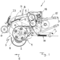
- the harvesting machine 1 shown in the figures can be designed to be attached to a tractor, not shown, and can include, for example, a headstock that can be attached to the tractor by means of a three-point linkage, or have a drawbar in order to design the harvesting machine as a semi-trailer and attach it to the tractor can.
- the harvesting machine 1 mentioned can be designed in the form of a loading wagon or a baler, but possibly also as a belt rake or merger.
- the harvesting machine 1 can include a machine frame 3, which can be supported on the ground via a chassis (not shown in detail), but, depending on the design, can also be held floating by the tractor via a trestle.
- the machine frame 3 mentioned carries a receiving conveyor 4, which collects crops from the ground and transfers them to a connecting conveyor 5, which can be, for example, a conveyor rotor equipped with a cutting mechanism in order to convey the picked crops into a bale forming chamber or the storage space of a loading wagon.
- the receiving conveyor 4 mentioned can have a spiked rotor 7, which is arranged horizontally and can extend with its axis of rotation 9 transversely to the direction of travel.
- the conveyor tines 8 of the spike rotor 7 can rotate uncontrolled around the said axis of rotation 9 on a circular path or in a controlled manner an optionally non-circular orbit around said axis of rotation 9.
- the spiked rotor 7 can have scraper strips 10 which extend in an arc around the axis of rotation 9 and between which the conveyor tines 8 protrude.
- the spike rotor 7 is suspended from the machine frame 3 via a pickup suspension 15, so that the spike rotor 7 can carry out up and down movements and can also tilt about a horizontal axis that is approximately parallel to the direction of travel.
- the pickup suspension 15 can include several suspension arms for this purpose, cf. Figure 1 and/or also provide a ball joint-like support for the pickup in a central section, as is known per se.
- the spiked rotor 7 can be supported on the ground by a tactile chassis 2 in order to be able to follow the ground contour as precisely as possible.
- a sensing chassis 2 can, for example, include 2 sensing wheels which run on the ground to the right and left of the spiked roller 7 and guide the spiked rotor over the ground.
- a floating, for example sensor-controlled, suspension can also be provided.
- a conveying aid 11 is provided above the spiked rotor 7, which has a baffle surface 12 which nestles around the circumference of the spiked rotor 7 or is arranged at an acute angle to the radial direction of the spiked rotor 7, in order to move crops thrown upwards by the spiked rotor 7 backwards to the connecting conveyor 5 to guide.
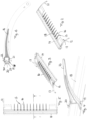
- the baffle surface 12 mentioned can be designed in various ways, for example having a baffle plate or a baffle cloth stretched by a clamping frame. Alternatively or additionally, the baffle surface 12 is also formed, at least in sections, by a bar grid 13, as shown in the figures.
- the said baffle surface 12 in the direction of the axis of rotation 9 of the spike rotor 7, the said baffle surface 12 extends in a segment from approximately 9 o'clock to 12 o'clock or 10 o'clock to 1 o'clock or 10 o'clock to 12 o'clock or in a quadrant which is in The direction of travel is at the front and above the spike rotor 7.
- the impact surface 12 mentioned can be concave, approximately slightly trough-shaped, on its side facing the spike rotor 7, although in principle a flat design is also possible.
- said baffle surface 12 extends at an acute angle to the vertical, for example inclined at an angle of approximately 30° to 60°.
- an inlet roller 14 can be connected to the baffle surface 12, which forms part of the conveying aid 11 and enables the crop to enter gently under the baffle surface 12.
- Said inlet roller 14 can extend lying transversely to the direction of travel and be rotatable about an axis of rotation, wherein said inlet roller 14 can be freely rotatable without a drive, but can also be actively driven if necessary.
- the inlet roller 14 mentioned is movably suspended together with the baffle surface 12, as will be explained below.
- the conveyor aid suspension 16 comprises a plurality of support arms 17, which are articulated on the machine frame 3 downstream of the receiving conveyor 4, for example in the area of the connecting conveyor 5, and from there project forward over the receiving conveyor 4 or extend laterally therefrom.
- the support arms 17 can be arranged laterally to the right and left of the conveying aid 11 or also to the side of the spike rotor 7, so that the conveying aid 11 together with the support arms 17 form an approximately U-shaped structure which extends over the spike rotor 7 and through which Support arms 17 is articulated downstream on the machine frame 3.
- the two support arms 17 are each pivotally mounted about a lying pivot axis 18 that extends transversely to the direction of travel 6, so that the support arms 17 can rock up and down.
- the machine frame-side bearings of the support arms 17 can be designed in the form of uniaxial swivel joints, but possibly also in the form of ball joints and / or simplified, multi-axis tiltable joints, which, in addition to the pivoting about the axis 18, also allow for tilting in a direction transverse to it allow.
- the tines 16 of the bar grid 13 of the baffle surface 12 are fastened with their front ends to a tine carrier 18, which extends across the pickup or its spiked rotor 7 or across the flow of conveyed material that runs over the spiked rotor 7.
- the said tine carrier 18 can extend over the entire width of the impact surface 12 and can be fastened with its two ends to the mentioned wire arms 17, by means of which the impact surface 12 is suspended on the machine frame 3 in a height-movable manner.
- the tines 16 encompass the tine carrier 18 mentioned and are clamped or held on the outside of the tine carrier 18 mentioned.
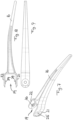
- the tines 16 each have a fastening mouth 19, which is attached to the front side or at one end of the tine body and is rigidly connected to the tine, whereby the said fastening mouth 19 can, for example, be attached to the front side so as to protrude from the end of the tine body.
- Each tine 16 can have its own fastening mouth 19, so that the tines are individually attached to the tine carrier 18, or some tines 16 can be combined into a group and have a common fastening mouth 19 with which they are attached as a group to the tine carrier 18 can be.
- the aforementioned fastening mouth 19 can be connected to the tine body in one piece, in a homogeneous manner in terms of material and/or structure or structure.
- the tines 16 including their fastening mouths 19 can be injection molded in one piece from plastic.
- said fastening mouth 19 can be contoured in a substantially U-shape and encompass the tine carrier 18 from three sides, with two opposite legs 21, 22 of the fastening mouth 19 coming to rest on opposite flat sides of the tine carrier 18.
- the fastening mouth 19 is advantageously adapted with its cross-sectional contour or with its inner contour to the outer contour of the tine carrier 18, so that the fastening mouth 19 can be fitted onto the tine carrier 18 with a precise fit and is firmly seated there, in particular secured against twisting.
- the tine carrier 18 can form a polygonal profile, for example a rectangular pipe cross section, in which case the fastening mouth 19 can have the said U-shaped cross section with two mutually parallel side legs 21, 22, cf. Fig. 4 and Fig. 6 .
- the tine carrier 18 can also be designed as a shaped tube with other, preferably non-circular cross sections.
- the opposite legs 21, 22 of the fastening jaw 19 can be clamped by a clamping device 20 on the outer sides of the tine carrier 18, the clamping device 20 being located in its longitudinal and/or axis of action 23 transversely to the longitudinal axis 24 of the tines 16 and transversely to the longitudinal axis of the tine carrier 18 extends, cf. Fig. 6 .
- the legs 21, 22 of the fastening mouth 19 have through holes 25, 26 which are aligned with one another and also aligned with a through hole 27 which passes through the tine carrier 18.
- the clamping means 20 can be inserted through the aligned through holes 25, 26, 27, wherein said clamping means 20 can be a screw bolt, which on the one hand supported on one leg with a screw bolt head and on the other hand can be clamped on the opposite leg 22 with a screwed-on nut, cf. Fig. 6 .
- the fastening jaw 19 can, in addition to the clamping means 20, also be held on the tine carrier 18 by a latching mechanism 28, in particular in order to secure the assembly position before the clamping means 20 are used.
- the latching 28 mentioned can include latching projections 29 and latching recesses 30, which are provided on the fastening mouth 19 and on the tine carrier 18 and come into engagement with one another when the tines 16 with their fastening mouths 19 are plugged into the mounting position on the tine carrier 18.
- ring-shaped locking webs can be provided as locking projections 29 around the aforementioned through holes 25, 26, which project from the legs 21, 22 of the fastening mouth 19 towards the inside and can snap into the through hole 27 in the tine carrier 18.
- the through hole 27 mentioned in the tine carrier 18 forms the locking recess 30 of the locking mechanism 28.
Landscapes
- Life Sciences & Earth Sciences (AREA)
- Environmental Sciences (AREA)
- Harvesting Machines For Specific Crops (AREA)
- Outside Dividers And Delivering Mechanisms For Harvesters (AREA)
Applications Claiming Priority (1)
| Application Number | Priority Date | Filing Date | Title |
|---|---|---|---|
| DE202022105171.2U DE202022105171U1 (de) | 2022-09-14 | 2022-09-14 | Landwirtschaftliche Erntemaschine |
Publications (1)
| Publication Number | Publication Date |
|---|---|
| EP4338575A1 true EP4338575A1 (fr) | 2024-03-20 |
Family
ID=87571396
Family Applications (1)
| Application Number | Title | Priority Date | Filing Date |
|---|---|---|---|
| EP23190984.7A Withdrawn EP4338575A1 (fr) | 2022-09-14 | 2023-08-11 | Moissonneuse agricole |
Country Status (2)
| Country | Link |
|---|---|
| EP (1) | EP4338575A1 (fr) |
| DE (1) | DE202022105171U1 (fr) |
Cited By (1)
| Publication number | Priority date | Publication date | Assignee | Title |
|---|---|---|---|---|
| EP4627908A1 (fr) * | 2024-04-05 | 2025-10-08 | Pöttinger Landtechnik GmbH | Moissonneuse agricole |
Citations (9)
| Publication number | Priority date | Publication date | Assignee | Title |
|---|---|---|---|---|
| US3157019A (en) * | 1963-08-15 | 1964-11-17 | Sperry Rand Corp | Reuseable resilient mounting for a rake tine |
| US4901511A (en) * | 1988-10-13 | 1990-02-20 | Yarmashev Jury N | Harvester reel rake bar |
| US5551221A (en) * | 1995-03-01 | 1996-09-03 | Sund; Lloyd P. | Replaceable pick-up tooth assembly for crop pick-up |
| US20140250855A1 (en) * | 2011-10-10 | 2014-09-11 | Cnh Industrial America Llc | Pick-up With Movable Windguard |
| EP3135099A1 (fr) | 2015-08-27 | 2017-03-01 | Josef Knüsel | Machine agricole comprenant un dispositif de ramassage |
| DE202017000595U1 (de) | 2017-02-03 | 2018-05-08 | Pöttinger Landtechnik Gmbh | Landwirtschaftliche Erntemaschine |
| EP2941946B1 (fr) | 2014-05-05 | 2018-07-04 | Roc S.R.L. | Unité de guidage pour produits agricoles destinée à un dispositif servant à récolter les produits agricoles et dispositif comprenant l'unité de guidage |
| DE102017001012A1 (de) | 2017-02-03 | 2018-08-09 | Pöttinger Landtechnik Gmbh | Landwirtschaftliche Erntemaschine |
| EP3669638A1 (fr) | 2018-12-20 | 2020-06-24 | PÖTTINGER Landtechnik GmbH | Engin d'abattage-façonnage agricole |
Family Cites Families (3)
| Publication number | Priority date | Publication date | Assignee | Title |
|---|---|---|---|---|
| US3698172A (en) | 1970-08-31 | 1972-10-17 | Int Harvester Co | Crop engaging tine means |
| US6324823B1 (en) | 1999-09-29 | 2001-12-04 | Macdon Industries Ltd. | Mounting a finger on the bat of a harvesting header |
| US11178821B2 (en) | 2019-06-10 | 2021-11-23 | Deere & Company | Reel finger |
-
2022
- 2022-09-14 DE DE202022105171.2U patent/DE202022105171U1/de active Active
-
2023
- 2023-08-11 EP EP23190984.7A patent/EP4338575A1/fr not_active Withdrawn
Patent Citations (9)
| Publication number | Priority date | Publication date | Assignee | Title |
|---|---|---|---|---|
| US3157019A (en) * | 1963-08-15 | 1964-11-17 | Sperry Rand Corp | Reuseable resilient mounting for a rake tine |
| US4901511A (en) * | 1988-10-13 | 1990-02-20 | Yarmashev Jury N | Harvester reel rake bar |
| US5551221A (en) * | 1995-03-01 | 1996-09-03 | Sund; Lloyd P. | Replaceable pick-up tooth assembly for crop pick-up |
| US20140250855A1 (en) * | 2011-10-10 | 2014-09-11 | Cnh Industrial America Llc | Pick-up With Movable Windguard |
| EP2941946B1 (fr) | 2014-05-05 | 2018-07-04 | Roc S.R.L. | Unité de guidage pour produits agricoles destinée à un dispositif servant à récolter les produits agricoles et dispositif comprenant l'unité de guidage |
| EP3135099A1 (fr) | 2015-08-27 | 2017-03-01 | Josef Knüsel | Machine agricole comprenant un dispositif de ramassage |
| DE202017000595U1 (de) | 2017-02-03 | 2018-05-08 | Pöttinger Landtechnik Gmbh | Landwirtschaftliche Erntemaschine |
| DE102017001012A1 (de) | 2017-02-03 | 2018-08-09 | Pöttinger Landtechnik Gmbh | Landwirtschaftliche Erntemaschine |
| EP3669638A1 (fr) | 2018-12-20 | 2020-06-24 | PÖTTINGER Landtechnik GmbH | Engin d'abattage-façonnage agricole |
Cited By (1)
| Publication number | Priority date | Publication date | Assignee | Title |
|---|---|---|---|---|
| EP4627908A1 (fr) * | 2024-04-05 | 2025-10-08 | Pöttinger Landtechnik GmbH | Moissonneuse agricole |
Also Published As
| Publication number | Publication date |
|---|---|
| DE202022105171U1 (de) | 2023-12-19 |
Similar Documents
| Publication | Publication Date | Title |
|---|---|---|
| DE60219756T2 (de) | Gerät zur Behandlung von Erntegut | |
| EP1980144B1 (fr) | Moissonneuse agricole | |
| DE2848451A1 (de) | Reihenschneid-anbaugeraet | |
| DE19740589A1 (de) | Aufnahmeeinheit für Erntegut | |
| EP4338575A1 (fr) | Moissonneuse agricole | |
| DE69117953T2 (de) | Heurechen- und wendemaschine | |
| DE202006008762U1 (de) | Niederhaltermechanismus für eine Pick-up | |
| EP4380347A1 (fr) | Tête de ramassage destinée à une récolteuse-hacheuse de préférence autotractée | |
| EP3669638B1 (fr) | Engin d'abattage-façonnage agricole | |
| DE3034268A1 (de) | Gabellose heuerntemaschine | |
| EP3092890B1 (fr) | Barre de coupe de moissonneuse | |
| DE2905478A1 (de) | Maeh- und konditioniervorrichtung | |
| EP3025577B1 (fr) | Andaineur universel | |
| DE3618825A1 (de) | Maehvorrichtung | |
| EP4124236B1 (fr) | Andaineuse dotée d'un râteau rotatif à réglage d'inclinaison | |
| DE3422426A1 (de) | Landmaschine zum verlagern von auf dem boden liegendem erntegut | |
| DE102006030508B4 (de) | Anordnung zur pendelnden Aufhängung eines Erntevorsatzes an einer Erntemaschine | |
| DE2448556A1 (de) | Kreiselheuwerbungsmaschine | |
| EP3666058A1 (fr) | Moissonneuse | |
| DE2909729A1 (de) | Heuwerbungsmaschine | |
| AT391579B (de) | Maehvorrichtung zum breit- und eingrasmaehen | |
| EP4295662A1 (fr) | Dents de brosse pour une andaineuse rotative | |
| DE1757270C (de) | Arbeitsgerät zum Weiterfbrdern von landwirtschaftlichem Fordergut | |
| DE29720527U1 (de) | Aufnahmeeinheit für Erntegut | |
| DE1482074C (de) | Heuwender |
Legal Events
| Date | Code | Title | Description |
|---|---|---|---|
| PUAI | Public reference made under article 153(3) epc to a published international application that has entered the european phase |
Free format text: ORIGINAL CODE: 0009012 |
|
| STAA | Information on the status of an ep patent application or granted ep patent |
Free format text: STATUS: THE APPLICATION HAS BEEN PUBLISHED |
|
| AK | Designated contracting states |
Kind code of ref document: A1 Designated state(s): AL AT BE BG CH CY CZ DE DK EE ES FI FR GB GR HR HU IE IS IT LI LT LU LV MC ME MK MT NL NO PL PT RO RS SE SI SK SM TR |
|
| STAA | Information on the status of an ep patent application or granted ep patent |
Free format text: STATUS: THE APPLICATION IS DEEMED TO BE WITHDRAWN |
|
| 18D | Application deemed to be withdrawn |
Effective date: 20240921 |