EP4338580A1 - Moissonneuse-batteuse automotrice - Google Patents
Moissonneuse-batteuse automotrice Download PDFInfo
- Publication number
- EP4338580A1 EP4338580A1 EP23186580.9A EP23186580A EP4338580A1 EP 4338580 A1 EP4338580 A1 EP 4338580A1 EP 23186580 A EP23186580 A EP 23186580A EP 4338580 A1 EP4338580 A1 EP 4338580A1
- Authority
- EP
- European Patent Office
- Prior art keywords
- threshing
- drum
- separating
- inlet
- combine harvester
- Prior art date
- Legal status (The legal status is an assumption and is not a legal conclusion. Google has not performed a legal analysis and makes no representation as to the accuracy of the status listed.)
- Granted
Links
Images




Classifications
-
- A—HUMAN NECESSITIES
- A01—AGRICULTURE; FORESTRY; ANIMAL HUSBANDRY; HUNTING; TRAPPING; FISHING
- A01F—PROCESSING OF HARVESTED PRODUCE; HAY OR STRAW PRESSES; DEVICES FOR STORING AGRICULTURAL OR HORTICULTURAL PRODUCE
- A01F7/00—Threshing apparatus
- A01F7/02—Threshing apparatus with rotating tools
- A01F7/04—Threshing apparatus with rotating tools with axles transverse to the feeding direction
-
- A—HUMAN NECESSITIES
- A01—AGRICULTURE; FORESTRY; ANIMAL HUSBANDRY; HUNTING; TRAPPING; FISHING
- A01F—PROCESSING OF HARVESTED PRODUCE; HAY OR STRAW PRESSES; DEVICES FOR STORING AGRICULTURAL OR HORTICULTURAL PRODUCE
- A01F12/00—Parts or details of threshing apparatus
- A01F12/18—Threshing devices
- A01F12/20—Threshing cylinders with ribs
-
- A—HUMAN NECESSITIES
- A01—AGRICULTURE; FORESTRY; ANIMAL HUSBANDRY; HUNTING; TRAPPING; FISHING
- A01F—PROCESSING OF HARVESTED PRODUCE; HAY OR STRAW PRESSES; DEVICES FOR STORING AGRICULTURAL OR HORTICULTURAL PRODUCE
- A01F12/00—Parts or details of threshing apparatus
- A01F12/30—Straw separators, i.e. straw walkers, for separating residual grain from the straw
- A01F12/39—Straw separators, i.e. straw walkers, for separating residual grain from the straw with straw carriers in the form of rotors or drums
-
- A—HUMAN NECESSITIES
- A01—AGRICULTURE; FORESTRY; ANIMAL HUSBANDRY; HUNTING; TRAPPING; FISHING
- A01F—PROCESSING OF HARVESTED PRODUCE; HAY OR STRAW PRESSES; DEVICES FOR STORING AGRICULTURAL OR HORTICULTURAL PRODUCE
- A01F12/00—Parts or details of threshing apparatus
- A01F12/30—Straw separators, i.e. straw walkers, for separating residual grain from the straw
- A01F12/395—Conical or cylindrical straw separators with internal working surface
Definitions
- the present application relates to a self-propelled combine harvester according to the preamble of claim 1.
- the combine harvester is intended and set up to harvest plants growing in a field, the plants being processed, among other things, by means of a threshing device.
- a threshing device This is designed as a tangential threshing device and includes a tangential pre-drum and a tangential threshing drum connected downstream of the pre-drum in the flow direction of a crop stream.
- the threshing device comprises a threshing concave, which surrounds both the pre-drum and the threshing drum, at least in some areas.
- the latter In the course of processing the respective crop, the latter is guided in a threshing gap between the pre-drum and the threshing concave or between the threshing drum and the threshing concave and processed in such a way that fruits of the crop are separated from remaining plant residues of the crop. A large part of the fruit is immediately separated from the plant residue using the threshing concave.
- the threshing concave can be movable relative to the threshing drum, so that a threshing gap located between the threshing drum and the threshing concave can be changed.
- the change in the thickness of the threshing gap is typically carried out depending on the prevailing boundary conditions such as moisture of the crop and crop throughput in order to optimize the threshing result.
- the threshing drum of the threshing device comprises a cylindrical drum body which can be rotated about its central axis and a plurality of beater bars which are arranged on an outer surface of the drum body.
- the blow bars each have a striking edge that is oriented parallel to the central axis of the drum body.
- the blow bars therefore extend parallel to the central axis along the drum body, with the blow bars preferably extending over an entire length of the drum body.
- the blow bars are intended to come into contact with the crop and to apply impact energy to the crop so that the fruit is "threshed", thereby separating the fruit from the plant residue.
- the blow bars each protrude in the radial direction relative to the central axis of the drum body in a direction away from the central axis over the outer lateral surface of the drum body.
- the radially outer striking edges of the blow bars describe a circumferential circle around the central axis, on which they move in the course of a rotary drive of the threshing drum.
- the circumference circle the striking edges have a striking radius in relation to the central axis.
- the blow bars are designed in such a way that the circumferential circles of all impact edges of all blow bars have at least essentially the same impact radius.
- the separating device comprises at least one axial separating rotor, preferably two axial separating rotors, each of which is mounted so that it can rotate about an axis of rotation.
- the separating rotors extend parallel to one another and are arranged next to one another when viewed in the longitudinal direction of the combine harvester.
- the separating device comprises an inlet head at its end facing the threshing device, into which the crop can be transferred starting from the threshing device.
- the inlet head has the function of feeding the crop flow in an orderly manner to at least one separating rotor.
- the at least one separating rotor has at its end facing the threshing device at least one inlet wing, which extends radially with respect to the axis of rotation of the respective separating rotor and is intended and set up to capture crop material transferred into an inlet area of the inlet head, which is assigned to the separating rotor and to set it in a rotational movement about the axis of rotation of the separating rotor.
- the crop is transported spirally by means of the separating rotor along its axis of rotation to a rear end of the separating device.
- the mechanical action of the separating rotor on the mixture results in the desired separation of the fruits from the plant residues.
- the fruits are separated through a threshing concave of the separating device downwards onto a screening device.
- the plant residues are finally ejected at a rear end of the combine while the fruits are collected in a grain tank.
- a combine harvester of the type described above is already known in the prior art. Please refer to the disclosure document for this purpose DE 42 32 450 A1 pointed out, which describes a self-propelled combine harvester with an axial separating device. The document is concerned with equalizing a torque load on the at least one separating rotor of the separating device.
- the transfer of the crop from the threshing device to the separating device has proven to be particularly critical for efficient operation of the combine harvester. This is due, among other things, to the fact that the crop flow has to be picked up and redirected by the separating device during the transfer, which results in a discontinuity in the flow of the crop. This can lead to disruptions, for example in the form of blockages or other influences that have a negative impact on the processing of the crop.
- the present application is therefore based on the object of providing a combine harvester in which the transfer of the crop from the threshing device to the separating device is optimized.
- the combine harvester according to the invention is characterized in that at least one inlet wing of the at least one separating rotor extends so far in the direction of the threshing drum that the inlet wing reaches up to a circumferential circle of blow bars of the threshing drum. This is done in such a way that the crop stream starting from the threshing drum can be transferred directly into an effective area of the inlet wing.
- a minimum distance between the circumferential circle of the striking edges of the blow bars and the inlet wing can be a maximum of 10 cm, preferably a maximum of 5 cm, more preferably a maximum of 3 cm.
- the combine harvester according to the invention has many advantages.
- an effective range of the inlet wing is expanded compared to the prior art, so that the crop, which is transferred from the threshing device to the separating device, immediately reaches the inlet head from the inlet wing of the at least one separating rotor recorded and processed accordingly.
- a flow path of the crop, which moves the crop unguided, ie without active influence by the threshing drum of the threshing device and/or by the separating rotor of the separating device, is minimized in this way.
- the separating device comprises at least two separating rotors, preferably exactly two separating rotors, which are arranged next to one another when viewed in the longitudinal direction of the combine harvester, with the axes of rotation of the separating rotors preferably extending parallel to one another.
- the inlet head comprises a number of inlet areas corresponding to the number of separating rotors, with one inlet area being assigned to one of the separating rotors.
- the crop flow is to be divided into the different inlet areas of the inlet head or the separating rotors during the transfer from the threshing device to the separating device.
- the at least one separating rotor is mounted in a bearing console of the inlet head at an end facing the threshing drum.
- the bearing bracket is housed in a housing so that the separating rotor bearing is protected from contamination.
- the inlet wing viewed in the axial direction of the separating rotor, extends over the housing of the bearing console.
- the housing is at least partially cylindrical, with a central axis of the cylindrical section of the housing extending parallel to the axis of rotation of the respective separating rotor. Further preferably, the central axis of the housing and the axis of rotation of the associated separating rotor are arranged congruently.
- the cylindrical section of the housing is preferably assigned to the area of influence of the inlet wing, so that the inlet wing continuously sweeps over an outer lateral surface of the housing in the course of a rotational drive of the separating rotor and can in this way prevent deposits of crop material on the housing.
- the inlet wing and the housing are preferably matched to one another in such a way that an outer diameter of the cylindrical section of the housing is matched to an inner diameter of the inlet wing, which it has in the area of the housing. In this way, the inlet wing is set up to sweep over the outer surface of the housing in the immediate vicinity.
- a corresponding design can be found in the following exemplary embodiment.
- the housing of the bearing console extends so far in the direction of the threshing drum that the housing extends up to the circumferential circle of the striking edges of the blow bars reaches the threshing drum.
- This configuration has the advantage that the at least one inlet area of the inlet head, which is assigned to the at least one separating rotor, can be moved closer to the threshing drum.
- the bearing bracket of the separating rotor which is typically arranged at one end of the separating rotor, can also be brought close to the threshing drum due to the geometry of the housing adapted to the circumferential circle of the striking edges, whereby the separating rotor can also be guided close to the threshing drum.
- This configuration accordingly favors the guidance of the at least one inlet blade of the separating rotor up to the circumferential circle of the striking edges of the blow bars.
- This embodiment also follows the idea of being able to capture the crop flow as quickly as possible by means of the separating rotor as soon as it reaches the separating device.
- the housing is shaped at its end facing the threshing drum in a manner adapted to the circumferential circle of the striking edges in the manner of a circular arc section.
- the housing is arranged throughout its height at a preferably constant distance from the circumferential circle.
- the combine harvester comprises a scraper edge which is oriented parallel to the central axis of the drum body of the threshing drum.
- the stripping edge is preferably formed on an end of the inlet head facing the threshing drum and is designed to strip the guided crop into the inlet head as the threshing drum rotates about the central axis.
- the scraper edge also extends directly to the circumferential circle of the striking edges of the beating bars of the threshing drum, so that the crop, as a result of the rotary drive of the threshing drum, is in relation to the central axis of the drum body is guided in a tangential direction, is deflected ("stripped off") from its tangential flow and is introduced into the inlet head in this way.
- the scraper edge - viewed in a cross section perpendicular to the central axis of the drum body - is arranged at a height level above the central axis of the drum body.
- the stripping edge is preferably arranged in height in an upper third area, more preferably in an upper quarter area, of the threshing drum.
- an inlet cross section of the inlet area of the inlet head extends over a significant part of a diameter of the threshing drum, so that the crop can easily enter the inlet head and a correspondingly large flow cross section is available. The formation of bottlenecks and the resulting obstruction of the crop flow is accordingly avoided.
- the scraper edge serves to strip off plant material into the inlet head that would otherwise be thrown over the inlet head in the tangential direction of the threshing drum.
- the stripping edge is arranged at least in sections vertically above a bearing point of a bearing bracket of the inlet head, by means of which the at least one separating rotor is mounted so that it can rotate about its axis of rotation.
- the scraper edge is formed on a housing, by means of which the bearing bracket is housed.
- the separating device comprises two axial separating rotors in the manner described and the inlet head correspondingly has two inlet areas, one of which is assigned to one of the separating rotors
- the combine harvester has a crop flow divider.
- This can in particular be designed in the form of a vertical partition between the inlet areas of the inlet head.
- the crop flow divider is suitable for dividing the crop flow transferred from the threshing device to the separating device between the two inlet areas of the inlet head. The flow of the crop during the transfer to the separating device is thereby improved, since the crop flow divider divides the crop flow into two parts, which are fed individually to the separating rotors.
- such an embodiment of the combine harvester according to the invention can be particularly advantageous, in which at least one basket segment of the threshing concave connects flush to an end of the inlet head facing the threshing device.
- This configuration allows the crop flow to pass from the concave to the inlet head without any obstacles, thereby promoting the flow of the crop.
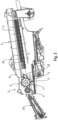
- a combine harvester 1 known from the prior art is exemplified by Figure 1 illustrated.
- This includes a cutting unit 25 , by means of which plants can be cut off, which can then be fed to a tangential threshing device 2 by means of an inclined conveyor 26 .
- the threshing device 2 includes a pre-drum 4 , a threshing drum 5 and a turning drum 27 , with central axes of the drums being aligned transversely to a longitudinal direction of the combine harvester 1 .
- the threshing device 2 includes a threshing concave 6 , which partially surrounds at least the pre-drum 4 and the threshing drum 5 .
- the processing of the harvested crop by means of the threshing device 2 results in fruits being detached from the plants and the plants are thus separated into the fruits and remaining plant residues.
- a large part of the fruit can be removed directly in the area of the threshing device 2 by means of the threshing concave 6 downwards onto a feed floor.
- a mixture of plant residues and detached fruits is transferred to a downstream separating device 3 by means of the turning drum 27 .
- the example shown is formed by a horde shaker.
- the separating device 3 has the task of separating the remaining fruits from the plant residues so that they can be obtained separately.
- the plant residues are finally ejected from the combine harvester 1 at a rear end.
- the fruits on the other hand, are collected in a grain tank and stored until further collection.
- an axial separating device 3 which has at least one separating rotor 7 , 8 .
- the example shown from the prior art results in an axial separating device 3 , which has two separating rotors 7 , 8 , which are arranged parallel to one another and next to one another when viewed in the longitudinal direction of the combine harvester 1 .
- the separating rotors 7 , 8 are each mounted so that they can rotate about an axis of rotation 20 .
- the separating device 3 includes an inlet head 10 facing the threshing device 2 , into which the crop emanating from the threshing device 2 is transferred.
- the inlet head 10 includes two inlet areas 29 , one of which is assigned to one of the separating rotors 7 , 8 .
- the inlet areas 29 are structurally separated from one another by means of a crop flow divider 28 , so that crop material that is transferred from the threshing device 2 to the separating device 3 is divided between the two inlet areas 29 by means of the crop flow divider 28 .
- the crop flow divider 28 is formed here by a vertical partition that separates the two inlet areas 29 from each other.
- a special feature of the Figure 2 The embodiment shown is that the threshing device 2 without an in Figure 1 shown turning drum 27 or another feed drum is designed so that the crop is transferred directly from the threshing drum 5 to the separating device 3 .
- the threshing drum 5 extends longitudinally along a central axis 11 of a drum body 12 and includes a plurality of beater bars 13 .
- the blow bars 13 are arranged on an outer lateral surface 14 of the drum body 12 of the threshing drum 5 , with the blow bars 13 protruding radially beyond the lateral surface 14 in relation to the central axis 11 of the drum body 12 .
- the blow bars 13 each include a striking edge 15 , which forms a radially outer end of a respective blow bar 13 .
- the blow bars 13 come into striking contact with the crop with their striking edges 15 , which causes the fruits to be separated from the plant residues.
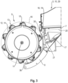
- the striking edges 15 which extend parallel to the central axis 11 , move in the course of a rotational drive of the drum body 12 on a circumferential circle 16 , which is in Figure 3 is illustrated by a dashed line.
- the circumferential circle 16 extends with respect to the central axis 11 in an impact radius 31 around the central axis 11 .
- the threshing concave 6 is connected flush to an end of the inlet head 10 facing the threshing device 2 .
- the threshing concave includes 6 rear basket segment 9 , which is connected directly and flush to the inlet head 10 .
- the combine harvester 1 which is not shown as a whole, comprises two separating rotors 7 , 8 which are arranged next to one another in the manner described above.
- the separating rotors 7 , 8 each have an inlet wing 17 , which is formed at an end of the respective separating rotor 7 , 8 facing the threshing device 2 .
- the respective inlet wing 17 extends so far towards the threshing drum 5 that it reaches as far as the circumferential circle 16 of the striking edges 15 of the blow bars 13 . This is particularly clear from: Figure 3 .
- a minimum distance of the circumferential circle 16 from the inlet wing 17 is only a few centimeters, here approx. 3 cm.
- the inlet wing 17 in the example shown is guided at its end facing the threshing drum 5 over a housing 19 of a bearing console 18 of the respective separating rotor 7 , 8 .
- the bearing bracket 18 has the function of providing a bearing point 23 for a shaft 24 of the respective separating rotor 7 , 8 , which forms the axis of rotation 20 around which the respective separating rotor 7 , 8 can be driven in rotation.
- the bearing console 18 is enclosed with the housing 19 described.
- the housing 19 is designed with a cylindrical cross section, with the respective inlet wing 17 being guided in the direction of the threshing drum 5 and over the housing 19 of the respective bearing console 18 .
- the housing 19 is also designed to reach up to the circumferential circle 16 of the striking edges 15 at its end facing the threshing device 2 , the housing 19 being shaped in a manner adapted to the circumferential circle in the manner of a circular arc section. This is particularly clear from the Figures 3 and 7 .
- the design has the advantage that crop material that is transferred from the threshing drum 5 to the separating device 3 should largely enter the inlet head 10 and, if possible, should not have the opportunity to pass the inlet head 10 in the tangential direction of the threshing drum 5 to be guided.
- a stripping edge 30 is formed on the housing 19 , which is explained separately below.
- the inlet wing 17 extends directly to the threshing drum 5 , the crop flow, which is transferred from the threshing drum 5 to the separating device 3 , can be detected directly in the respective inlet area 29 of the inlet head 10 by means of the inlet wing 17 .
- the crop stream is transferred from the threshing drum 5 directly into an effective area of the respective inlet wing 17 .
- the transfer of the crop flow from the threshing device 2 is optimized, since in particular the flow direction or its change, which in principle must take place in the course of the transfer of the crop from the threshing device 2 to the separating device 3 , immediately when the crop enters the respective inlet areas 29 begins.
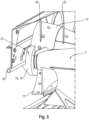
- the inlet head 10 is equipped in the inlet areas 29 with additional guide elements 22 , which extend partially helically on an inner lateral surface of the inlet head 10 and are suitable for giving the respective crop stream the desired helical flow direction about the axis of rotation 20 of the respective separating rotor 7 . 8 to imprint.
- guide elements 22 result particularly well from the Figures 4 and 5 .
- the combine harvester according to the invention 1 in the example shown comprises a stripping edge 30 which is formed at an end of the inlet head 10 of the separating device 3 facing the threshing device 2 and extends parallel to the central axis 11 of the drum body 12 .
- the scraper edge 30 results particularly well from the Figures 6 and 7 . It serves to strip crops that are guided tangentially with respect to the central axis 11 of the drum body 12 and which are moved by the threshing drum 5 from the threshing drum 5 and in this way to transfer them into the inlet head 10 .
- the stripping edge 30 is preferably arranged in height above the central axis 11 of the drum body 12 , with the stripping edge 30 being located in an upper quarter region of the threshing drum 5 in the example shown.
- Figure 3 the stripping edge 30 is designed to be divided, with the stripping edge 30 comprising two mutually opposite outer sections as well as a middle section located between the outer sections, which is assigned to the crop flow divider 28 between the inlet areas 29 .
- Figure 7 is particularly clear from:
- the middle section of the stripping edge 30 is arranged in height above the bearing point 23 of the respective separating rotor 7 , 8 , while the outer sections are at least essentially at the same height level as the axes of rotation 20 of the separating rotors 7 , 8 .
- the arrangement of the outer sections of the scraper edge 30 at a lower height level reduces unintentional lateral ejection of crop material during the transfer from the threshing device 2 to the separating device 3 . This is not necessary in the middle section of the scraper edge 30 , so that this is arranged higher than the outer sections of the scraper edge 30 in order to increase the overall entry cross section of the inlet head 10 and thereby improve the entry of the crop into the inlet head 10 . Stripping crops from the threshing drum 5 prevents the crops from being thrown over the threshing drum 5 . This minimizes the risk of a blockage or other disruption to the flow of the crop.
Landscapes
- Life Sciences & Earth Sciences (AREA)
- Environmental Sciences (AREA)
- Threshing Machine Elements (AREA)
Applications Claiming Priority (1)
| Application Number | Priority Date | Filing Date | Title |
|---|---|---|---|
| DE102022123311.1A DE102022123311A1 (de) | 2022-09-13 | 2022-09-13 | Selbstfahrender Mähdrescher |
Publications (2)
| Publication Number | Publication Date |
|---|---|
| EP4338580A1 true EP4338580A1 (fr) | 2024-03-20 |
| EP4338580B1 EP4338580B1 (fr) | 2025-12-24 |
Family
ID=87426587
Family Applications (1)
| Application Number | Title | Priority Date | Filing Date |
|---|---|---|---|
| EP23186580.9A Active EP4338580B1 (fr) | 2022-09-13 | 2023-07-20 | Moissonneuse-batteuse automotrice |
Country Status (2)
| Country | Link |
|---|---|
| EP (1) | EP4338580B1 (fr) |
| DE (1) | DE102022123311A1 (fr) |
Citations (6)
| Publication number | Priority date | Publication date | Assignee | Title |
|---|---|---|---|---|
| DE3537959A1 (de) * | 1985-10-25 | 1987-05-07 | Claas Ohg | Selbstfahrender maehdrescher |
| DE3601359A1 (de) * | 1986-01-18 | 1987-07-23 | Claas Ohg | Selbstfahrender maehdrescher |
| DE4232450A1 (de) | 1992-09-28 | 1994-03-31 | Claas Ohg | Selbstfahrender Mähdrescher |
| US6129629A (en) * | 1997-05-27 | 2000-10-10 | Claas Selbstfahrende Erntemaschinen Gmbh | Intake zone for axial separator |
| EP1147701A1 (fr) * | 2000-04-19 | 2001-10-24 | CLAAS Selbstfahrende Erntemaschinen GmbH | Moissonneuse-batteuse automotrice |
| EP4230025A1 (fr) * | 2022-02-21 | 2023-08-23 | CLAAS Selbstfahrende Erntemaschinen GmbH | Moissonneuse-batteuse automotrice |
-
2022
- 2022-09-13 DE DE102022123311.1A patent/DE102022123311A1/de active Pending
-
2023
- 2023-07-20 EP EP23186580.9A patent/EP4338580B1/fr active Active
Patent Citations (6)
| Publication number | Priority date | Publication date | Assignee | Title |
|---|---|---|---|---|
| DE3537959A1 (de) * | 1985-10-25 | 1987-05-07 | Claas Ohg | Selbstfahrender maehdrescher |
| DE3601359A1 (de) * | 1986-01-18 | 1987-07-23 | Claas Ohg | Selbstfahrender maehdrescher |
| DE4232450A1 (de) | 1992-09-28 | 1994-03-31 | Claas Ohg | Selbstfahrender Mähdrescher |
| US6129629A (en) * | 1997-05-27 | 2000-10-10 | Claas Selbstfahrende Erntemaschinen Gmbh | Intake zone for axial separator |
| EP1147701A1 (fr) * | 2000-04-19 | 2001-10-24 | CLAAS Selbstfahrende Erntemaschinen GmbH | Moissonneuse-batteuse automotrice |
| EP4230025A1 (fr) * | 2022-02-21 | 2023-08-23 | CLAAS Selbstfahrende Erntemaschinen GmbH | Moissonneuse-batteuse automotrice |
Also Published As
| Publication number | Publication date |
|---|---|
| DE102022123311A1 (de) | 2024-03-14 |
| EP4338580B1 (fr) | 2025-12-24 |
Similar Documents
| Publication | Publication Date | Title |
|---|---|---|
| DE2628414C2 (fr) | ||
| DE3918393C2 (de) | Getreideerntemaschine | |
| DE2000553C3 (fr) | ||
| EP1106048B1 (fr) | Dispositif d'introduction et de cueillage d'un dispositif de chargement de récoltes | |
| DE2430718B2 (de) | Mähdrescher | |
| DE19959338A1 (de) | Einzugs- und Pflückeinrichtung sowie Erntemaschine | |
| EP3391725A1 (fr) | Ensemble à convoyeur à vis pour une moissonneuse-batteuse | |
| DE2943840A1 (de) | Maehdrescher | |
| DE19803336A1 (de) | Rotationsförderer mit einem Rotationskörper und wenigstens einem Mitnehmer und Erntemaschine mit einem solchen Rotationsförderer | |
| DE102018102594A1 (de) | Mähdrescher | |
| EP3453248A1 (fr) | Moissonneuse-batteuse | |
| DE3025380C2 (fr) | ||
| EP4338578A1 (fr) | Tambour batteur pour un dispositif batteur d'une moissonneuse-batteuse ainsi que moissonneuse-batteuse | |
| DE3135118C2 (de) | Mähdrescher mit Axialdreschmaschine | |
| DE1222307B (de) | Dresch- und Trennvorrichtung | |
| DE2922982C2 (fr) | ||
| EP4230024A1 (fr) | Moissonneuse-batteuse automotrice | |
| DD215924A5 (de) | Steinfangvorrichtung fuer maehdrescher | |
| EP1967061B1 (fr) | Hache-paille et moissonneuse équipée de celle-ci | |
| DE1938082C3 (de) | Dresch- und Reinigungseinrichtung für Mähgut | |
| EP4338580B1 (fr) | Moissonneuse-batteuse automotrice | |
| EP4338579B1 (fr) | Moissonneuse-batteuse automotrice | |
| EP4349183A1 (fr) | Machine de récolte de cucurbitacées | |
| EP4230025A1 (fr) | Moissonneuse-batteuse automotrice | |
| BE1021334B1 (de) | Mähdrescher mit einer zwischen der drescheinrichtung und der reinigung angeordneten nachdrescheinrichtung |
Legal Events
| Date | Code | Title | Description |
|---|---|---|---|
| PUAI | Public reference made under article 153(3) epc to a published international application that has entered the european phase |
Free format text: ORIGINAL CODE: 0009012 |
|
| STAA | Information on the status of an ep patent application or granted ep patent |
Free format text: STATUS: THE APPLICATION HAS BEEN PUBLISHED |
|
| AK | Designated contracting states |
Kind code of ref document: A1 Designated state(s): AL AT BE BG CH CY CZ DE DK EE ES FI FR GB GR HR HU IE IS IT LI LT LU LV MC ME MK MT NL NO PL PT RO RS SE SI SK SM TR |
|
| P01 | Opt-out of the competence of the unified patent court (upc) registered |
Effective date: 20240320 |
|
| STAA | Information on the status of an ep patent application or granted ep patent |
Free format text: STATUS: REQUEST FOR EXAMINATION WAS MADE |
|
| 17P | Request for examination filed |
Effective date: 20240920 |
|
| RBV | Designated contracting states (corrected) |
Designated state(s): AL AT BE BG CH CY CZ DE DK EE ES FI FR GB GR HR HU IE IS IT LI LT LU LV MC ME MK MT NL NO PL PT RO RS SE SI SK SM TR |
|
| GRAP | Despatch of communication of intention to grant a patent |
Free format text: ORIGINAL CODE: EPIDOSNIGR1 |
|
| STAA | Information on the status of an ep patent application or granted ep patent |
Free format text: STATUS: GRANT OF PATENT IS INTENDED |
|
| INTG | Intention to grant announced |
Effective date: 20250716 |
|
| GRAS | Grant fee paid |
Free format text: ORIGINAL CODE: EPIDOSNIGR3 |
|
| GRAA | (expected) grant |
Free format text: ORIGINAL CODE: 0009210 |
|
| STAA | Information on the status of an ep patent application or granted ep patent |
Free format text: STATUS: THE PATENT HAS BEEN GRANTED |
|
| AK | Designated contracting states |
Kind code of ref document: B1 Designated state(s): AL AT BE BG CH CY CZ DE DK EE ES FI FR GB GR HR HU IE IS IT LI LT LU LV MC ME MK MT NL NO PL PT RO RS SE SI SK SM TR |
|
| REG | Reference to a national code |
Ref country code: CH Ref legal event code: F10 Free format text: ST27 STATUS EVENT CODE: U-0-0-F10-F00 (AS PROVIDED BY THE NATIONAL OFFICE) Effective date: 20251224 Ref country code: GB Ref legal event code: FG4D Free format text: NOT ENGLISH |
|
| REG | Reference to a national code |
Ref country code: DE Ref legal event code: R096 Ref document number: 502023002564 Country of ref document: DE |
|
| REG | Reference to a national code |
Ref country code: LT Ref legal event code: MG9D |
|
| PG25 | Lapsed in a contracting state [announced via postgrant information from national office to epo] |
Ref country code: NO Free format text: LAPSE BECAUSE OF FAILURE TO SUBMIT A TRANSLATION OF THE DESCRIPTION OR TO PAY THE FEE WITHIN THE PRESCRIBED TIME-LIMIT Effective date: 20260324 |
|
| PG25 | Lapsed in a contracting state [announced via postgrant information from national office to epo] |
Ref country code: HR Free format text: LAPSE BECAUSE OF FAILURE TO SUBMIT A TRANSLATION OF THE DESCRIPTION OR TO PAY THE FEE WITHIN THE PRESCRIBED TIME-LIMIT Effective date: 20251224 Ref country code: FI Free format text: LAPSE BECAUSE OF FAILURE TO SUBMIT A TRANSLATION OF THE DESCRIPTION OR TO PAY THE FEE WITHIN THE PRESCRIBED TIME-LIMIT Effective date: 20251224 |
|
| PG25 | Lapsed in a contracting state [announced via postgrant information from national office to epo] |
Ref country code: RS Free format text: LAPSE BECAUSE OF FAILURE TO SUBMIT A TRANSLATION OF THE DESCRIPTION OR TO PAY THE FEE WITHIN THE PRESCRIBED TIME-LIMIT Effective date: 20260324 |
|
| PG25 | Lapsed in a contracting state [announced via postgrant information from national office to epo] |
Ref country code: LV Free format text: LAPSE BECAUSE OF FAILURE TO SUBMIT A TRANSLATION OF THE DESCRIPTION OR TO PAY THE FEE WITHIN THE PRESCRIBED TIME-LIMIT Effective date: 20251224 |
|
| REG | Reference to a national code |
Ref country code: NL Ref legal event code: MP Effective date: 20251224 |
|
| PG25 | Lapsed in a contracting state [announced via postgrant information from national office to epo] |
Ref country code: BG Free format text: LAPSE BECAUSE OF FAILURE TO SUBMIT A TRANSLATION OF THE DESCRIPTION OR TO PAY THE FEE WITHIN THE PRESCRIBED TIME-LIMIT Effective date: 20251224 |