EP4338640A1 - Abdeckung für klappbare elektronische vorrichtung mit stifthalter - Google Patents
Abdeckung für klappbare elektronische vorrichtung mit stifthalter Download PDFInfo
- Publication number
- EP4338640A1 EP4338640A1 EP22853364.2A EP22853364A EP4338640A1 EP 4338640 A1 EP4338640 A1 EP 4338640A1 EP 22853364 A EP22853364 A EP 22853364A EP 4338640 A1 EP4338640 A1 EP 4338640A1
- Authority
- EP
- European Patent Office
- Prior art keywords
- cover
- pen holder
- guide rail
- pen
- electronic device
- Prior art date
- Legal status (The legal status is an assumption and is not a legal conclusion. Google has not performed a legal analysis and makes no representation as to the accuracy of the status listed.)
- Pending
Links
Images





Classifications
-
- A—HUMAN NECESSITIES
- A45—HAND OR TRAVELLING ARTICLES
- A45C—PURSES; LUGGAGE; HAND CARRIED BAGS
- A45C11/00—Receptacles for purposes not provided for in groups A45C1/00-A45C9/00
-
- H—ELECTRICITY
- H04—ELECTRIC COMMUNICATION TECHNIQUE
- H04B—TRANSMISSION
- H04B1/00—Details of transmission systems, not covered by a single one of groups H04B3/00 - H04B13/00; Details of transmission systems not characterised by the medium used for transmission
- H04B1/38—Transceivers, i.e. devices in which transmitter and receiver form a structural unit and in which at least one part is used for functions of transmitting and receiving
- H04B1/3827—Portable transceivers
- H04B1/3888—Arrangements for carrying or protecting transceivers
-
- A—HUMAN NECESSITIES
- A45—HAND OR TRAVELLING ARTICLES
- A45C—PURSES; LUGGAGE; HAND CARRIED BAGS
- A45C11/00—Receptacles for purposes not provided for in groups A45C1/00-A45C9/00
- A45C11/002—Receptacles for purposes not provided for in groups A45C1/00-A45C9/00 for storing portable handheld communication devices, e.g. pagers or smart phones
-
- A—HUMAN NECESSITIES
- A45—HAND OR TRAVELLING ARTICLES
- A45C—PURSES; LUGGAGE; HAND CARRIED BAGS
- A45C13/00—Details; Accessories
-
- A—HUMAN NECESSITIES
- A45—HAND OR TRAVELLING ARTICLES
- A45C—PURSES; LUGGAGE; HAND CARRIED BAGS
- A45C13/00—Details; Accessories
- A45C13/005—Hinges
-
- A—HUMAN NECESSITIES
- A45—HAND OR TRAVELLING ARTICLES
- A45C—PURSES; LUGGAGE; HAND CARRIED BAGS
- A45C15/00—Purses, bags, luggage or other receptacles covered by groups A45C1/00 - A45C11/00, combined with other objects or articles
-
- G—PHYSICS
- G06—COMPUTING OR CALCULATING; COUNTING
- G06F—ELECTRIC DIGITAL DATA PROCESSING
- G06F3/00—Input arrangements for transferring data to be processed into a form capable of being handled by the computer; Output arrangements for transferring data from processing unit to output unit, e.g. interface arrangements
- G06F3/01—Input arrangements or combined input and output arrangements for interaction between user and computer
- G06F3/03—Arrangements for converting the position or the displacement of a member into a coded form
- G06F3/033—Pointing devices displaced or positioned by the user, e.g. mice, trackballs, pens or joysticks; Accessories therefor
- G06F3/0354—Pointing devices displaced or positioned by the user, e.g. mice, trackballs, pens or joysticks; Accessories therefor with detection of two-dimensional [2D] relative movements between the device, or an operating part thereof, and a plane or surface, e.g. 2D mice, trackballs, pens or pucks
- G06F3/03545—Pens or stylus
-
- G—PHYSICS
- G09—EDUCATION; CRYPTOGRAPHY; DISPLAY; ADVERTISING; SEALS
- G09F—DISPLAYING; ADVERTISING; SIGNS; LABELS OR NAME-PLATES; SEALS
- G09F9/00—Indicating arrangements for variable information in which the information is built-up on a support by selection or combination of individual elements
- G09F9/30—Indicating arrangements for variable information in which the information is built-up on a support by selection or combination of individual elements in which the desired character or characters are formed by combining individual elements
- G09F9/301—Indicating arrangements for variable information in which the information is built-up on a support by selection or combination of individual elements in which the desired character or characters are formed by combining individual elements flexible foldable or roll-able electronic displays, e.g. thin LCD, OLED
Definitions
- the disclosure relates to a cover for a foldable electronic device that includes a pen holder.
- a foldable electronic device may include a flexible display having a partial area deformable to be flat or curved.
- the foldable electronic device may include a first housing on one side of a bending area of the flexible display and a second housing on an opposite side of the bending area of the flexible display.
- the foldable electronic device may include a hinge structure that connects the first housing and the second housing such that the first housing and the second housing are foldable and a hinge housing that covers the hinge structure.
- the foldable electronic device may include a pen as an input device.
- the foldable electronic device may include a pen holder having a pen storage space formed therein.
- Embodiments of the disclosure provide a protective cover for a foldable electronic device from which a pen and a pen holder are detachable and that supports folding and unfolding motions of the foldable electronic device.
- a cover for an electronic device includes: a first cover portion configured to be coupled to a first housing of the electronic device, a second cover portion configured to be coupled to a second housing of the electronic device, a connecting portion provided between the first cover portion and the second cover portion and extending in a first direction, the connecting portion being configured such that the first cover portion and the second cover portion are folded to be superimposed on each other or are unfolded, and a pen holder configured to at least partially accommodate a pen and mounted on the connecting portion to be detachable.
- the cover for the foldable electronic device may include the guide rail and the pen holder slidably coupled to the guide rail. Accordingly, the pen holder may be easily attached and detached depending on a user's selection. Furthermore, the pen holder may be configured such that the pen is stored therein. Accordingly, depending on the user's selection, the pen may be removed alone, or the pen and the pen holder may be removed together.
- the disclosure may provide various effects that are directly or indirectly recognized.
- FIG. 1 is a diagram illustrating an example foldable electronic device in an unfolded (e.g., flat) state according to various embodiments.
- FIG. 1 is a view illustrating the foldable electronic device to which a cover for the foldable electronic device is coupled according various embodiments.
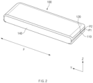
- FIG. 2 is a perspective view illustrating the foldable electronic device in a folded state according to various embodiments.
- FIG. 2 is a view illustrating the foldable electronic device to which the cover for the foldable electronic device is coupled according to various embodiments.
- the foldable electronic device 100 may include a first housing 110, a second housing 120, a hinge housing 140, and a display 130.
- first housing 110 and the second housing 120 may be folded or unfolded with a folding axis F therebetween.
- the first housing 110 and the second housing 120 may be configured to rotate in opposite directions about axes of rotation parallel to the folding axis F, respectively.
- the first housing 110 may rotate in the clockwise direction
- the second housing 120 may rotate in the counterclockwise direction.
- the hinge housing 140 may be disposed between the first housing 110 and the second housing 120. In the flat state, the hinge housing 140 may be hidden by the first housing 110 and the second housing 120, and in the folded state, the hinge housing 140 may be exposed to the outside.
- the hinge housing 140 may have a shape extending in the y-axis direction as a whole.
- the hinge housing 140 may have a hinge structure (not illustrated) disposed therein for rotating the first housing 110 and the second housing 120.
- the display 130 may be provided to be at least partially flexible.
- the display 130 may include a first area 131 and a second area 132 that are flat in the flat state and the folded state, and a folding are 133 that is curved in the folded state and flat in the flat state.
- the first area 131 may be at least partially disposed in the first housing 110
- the second area 132 may be at least partially disposed in the second housing 120.
- the folding area 133 may be defined between the first area 131 and the second area 132.
- the folding area 133 may be deformed to be flat or curved in a folding or unfolding motion of the electronic device 100.
- the electronic device 100 may include camera modules 139 and 129.
- the camera modules 139 and 129 may be disposed under the display 130.
- the first camera module 139 may include a punch hole camera module disposed under the second area 132.
- the second camera module 129 may include a punch hole camera module disposed under a sub-display 128.
- the first housing 110 may include a first back cover 116 that forms a rear surface 110B in the flat state.
- the sub-display 128 may be disposed on the first back cover 116.
- the second housing 120 may include a second back cover 126 that forms a rear surface 120B in the flat state.
- a third camera module 119 may be disposed on the second back cover 126.
- a first edge P1 of the electronic device 100 and a second edge P2 of the electronic device 100 that are parallel to the folding axis F may be defined.
- the flat state of the electronic device 100 will be described below with reference to FIG. 1 .
- the flat state may include the state in which the folding area 133 of the display 130 is flat.
- the flat state may include the state in which the first area 131 and the second area 132 of the display 130 are flat to face the same direction.
- the flat state may include the state in which the first normal vector of the first area 131 and the second normal vector of the second area 132 of the display 130 are parallel to each other.
- the folded state may refer to the state in which the first edge P1 and the second edge P2 substantially make contact with each other.
- the folding area 133 in the folded state may be curved.
- the hinge housing 140 may form at least a portion of a surface of the electronic device 100.
- the hinge housing 140 may be visually exposed between the first housing 110 and the second housing 120.
- FIGS. 3 and 4 are perspective views illustrating a cover including a pen holder for the foldable electronic device (hereinafter, referred to as the cover), according to various embodiments.
- the cover 200 may include a first cover portion 210 coupled to the first housing 110 of the electronic device 100, a second cover portion 220 coupled to the second housing 120 of the electronic device 100, a connecting portion 230 connecting the first cover portion 210 and the second cover portion 220, and the pen holder 250.
- the first cover portion 210 may be provided to surround at least a portion of the first housing 110 of the electronic device 100.
- the first cover portion 210 may be coupled to the first housing 110 to cover at least a portion of the rear surface 110B of the first housing 110.
- the first cover portion 210 may at least partially cover the first back cover 116 of the first housing 110.
- the first cover portion 210 may include a display area 218 through which the sub-display 128 is visible.
- the display area 228 may include a transparent area.
- the first cover portion 210 may face a first area 221 of the second cover portion 220 by bending of the connecting portion 230, or may be unfolded to form substantially the same plane with the first area 221 of the second cover portion 220.
- the second cover portion 220 may be provided to surround at least a portion of the second housing 120 of the electronic device 100.
- the second cover portion 220 may be coupled to the second housing 120 to cover at least portions of the rear surface 120B and the side surface 120C of the second housing 120.
- the second cover portion 220 may at least partially cover the second back cover 126 of the second housing 120.
- the second cover portion 220 may include the first area 221 that covers at least a portion of the rear surface 120B of the second housing 120 and a second area 222 that covers at least a portion of the side surface 120C of the second housing 120.
- the second area 222 may extend from at least a portion of the periphery of the first area 221.
- the first area 221 may at least partially make contact with the second back cover 126 of the second housing 120.
- an opening area 229 corresponding to a camera module (e.g., the camera module 119) of the electronic device 100 may be formed in the second cover portion 220.
- the opening area 229 may be formed in the first area 221 of the second cover portion 220.
- the opening area 229 may be formed in the first area 221 and/or the second area 222 of the second cover portion 220 depending on the positions of various modules provided in the electronic device 100.
- first cover portion 210 and the second cover portion 220 may be folded or unfolded with the folding axis F therebetween.
- a flat state and a folded state of the cover 200 may be defined by a flat state and a folded state of the electronic device 100.
- the flat state may include the state in which the first cover portion 210 and the first area 221 of the second cover portion 220 form substantially the same plane.
- FIGS. 3 and 4 illustrate the cover 200 in the flat state.
- the folded state may include the state in which the first cover portion 210 at least partially makes contact with the second area 222 of the second cover portion 220.
- the connecting portion 230 may be defined between the first cover portion 210 and the second cover portion 220 and may connect the first cover portion 210 and the second cover portion 220.
- the connecting portion 230 may be configured such that the first cover portion 210 and the second cover portion 220 are folded toward each other or unfolded away from each other.
- the connecting portion 230 may be configured to be at least partially flexible.
- the connecting portion 230 may be bent depending on a folding or unfolding motion of the electronic device 100. As the connecting portion 230 is bent, the first cover portion 210 and the second cover portion 220 may be folded or unfolded. In an embodiment, in a folded state, the connecting portion 230 may at least partially face the hinge housing 140.
- the connecting portion 230 may have a shape extending parallel to the folding axis F.
- the first cover portion 210 and the second cover portion 220 may be connected to opposite sides of the connecting portion 230 that are perpendicular to the folding axis F.
- the connecting portion 230 may include an inner surface 230b and an outer surface 230a facing away from the inner surface 230b.
- the inner surface 230b when viewed in a flat state, may be defined as a surface facing the hinge housing 140 of the electronic device 100.
- the pen holder 250 may be coupled to the outer surface 230a of the connecting portion 230.
- the connecting portion 230 may include a guide rail 240 to which the pen holder 250 is coupled.
- the guide rail 240 may be configured to guide a sliding direction S of the pen holder 250 when the pen holder 250 is mounted.
- the guide rail 240 may be formed on the outer surface 230a of the connecting portion 230.
- the guide rail 240 may have a shape extending parallel to the folding axis F.
- the guide rail 240 may extend parallel to the extension direction of the connecting portion 230.
- the pen holder 250 may be coupled to the connecting portion 230 so as to be detachable.
- the pen holder 250 may extend parallel to the folding axis F.
- the pen holder 250 may include a protruding portion 251 (refer to FIG. 5 ) at least partially inserted into the guide rail 240.
- the protruding portion 251 may extend parallel to the folding axis F.
- a pen 258 may be at least partially accommodated in the pen holder 250.
- the pen holder 250 may be provided in a shape surrounding at least a portion of the pen 258.
- a first end portion of the pen 258 may be surrounded by the pen holder 250, and a second end portion of the pen 258 may be exposed to the outside.
- the first end portion of the pen 258 may include a pen tip.
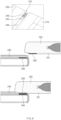
- FIG. 5 is a diagram illustrating the pen holder of the cover for the foldable electronic device according to various embodiments.
- FIG. 6 is a sectional view of the cover for the foldable electronic device according to various embodiments.
- the illustrated sliding direction S may refer to the direction in which the pen holder 250 is mounted on, or removed from, the connecting portion 230.
- the sliding direction S may be parallel to the folding axis F of the electronic device 100.
- the sliding direction S may be parallel to the y-axis.
- the guide rail 240 may extend in the extension direction of the connecting portion 230 (e.g., the y-axis direction or the direction of the folding axis F).
- the guide rail 240 may be provided in a form in which a first end portion 241 is closed and a second end portion 242 is open.
- the protruding portion 251 of the pen holder 250 may be at least partially accommodated in the guide rail 240.
- a second depression 245 may be provided on the guide rail 240.
- the second depression 245 may be formed in a position adjacent to the second end portion 242 of the guide rail 240.
- the second depression 245 may be formed in a position corresponding to a fourth end portion 253 of the pen holder 250 in the state in which the pen holder 250 is completely mounted.
- a second protrusion 255 of the pen holder 250 may be at least partially inserted into the second depression 245.
- the pen holder 250 may be inserted into the second end portion 242 of the guide rail 240 and slid in the direction from the second end portion 242 toward the first end portion 241 of the guide rail 240 and thus may be mounted on the connecting portion 230.
- a first sliding direction S may be defined as a direction in which the pen holder 250 is mounted on the connecting portion 230
- a second sliding direction S may be defined as a direction in which the pen holder 250 is removed from the connecting portion 230.
- the pen holder 250 may include a holder portion 256 at least partially surrounding the pen 258, the protruding portion 251 formed on the lower surface 250a of the holder portion 256, and a first protrusion 254 and the second protrusion 255 formed on the protruding portion 251.
- the holder portion 256 may include a hollow portion (e.g., a hollow portion 250h of FIG. 12 ) in which the pen 258 is disposed.
- the lower surface 250a of the holder portion 256 may have a length corresponding to that of the pen 258, and the upper surface 250b of the holder portion 256 may be shorter than the pen 258.
- the hollow portion of the holder portion 256 (e.g., the hollow portion 250h of FIG. 12 ) may be provided in a shape corresponding to the shape of the pen 258.
- the holder portion 256 may be provided to surround a portion of the pen 258.
- the portion of the pen 258 may include a pen tip 258c.
- the protruding portion 251 may protrude from the lower surface 250a of the holder portion 256.
- the protruding portion 251 may protrude in the z-axis direction.
- the protruding portion 251 may be at least partially accommodated in the guide rail 240.
- the protruding portion 251 may extend in a direction substantially parallel to the extension direction of the guide rail 240 (e.g., the sliding direction S).
- the protruding portion 251 may extend a length substantially the same as the extension length of the guide rail 240.
- the third end portion 252 and a fourth end portion 253 may be defined on the protruding portion 251 of the pen holder 250.
- the third end portion 252 may be defined as a portion corresponding to the first end portion 241 of the guide rail 240 in the state in which the pen holder 250 is completely mounted on the connecting portion 230
- the fourth end portion 253 may be defined as a portion corresponding to the second end portion 242 of the guide rail 240 in the state in which the pen holder 250 is completely mounted on the connecting portion 230.
- the protruding portion 251 may include the second protrusion 255 for hook coupling.
- the second protrusion 255 may be formed in a position adjacent to the third end portion 252 of the protruding portion 251.
- the second protrusion 255 may include a portion protruding from the third end portion 252 of the protruding portion 251 in the first sliding direction S.
- the second protrusion 255 may be at least partially inserted into the second depression 245 formed on the first end portion 241 of the guide rail 240.
- the pen holder 250 and the connecting portion 230 may be hook-coupled by insertion of the second protrusion 255 of the protruding portion 251 into the second depression 245 of the guide rail 240.
- the second depression 245 of the guide rail 240 may be defined by a bottom surface 243 and an inner wall 241a of the first end portion 241 of the guide rail 240.
- the inner wall 241a of the first end portion 241 of the guide rail 240 may protrude in the second sliding direction S so as to be engaged with the second protrusion 255.
- the second protrusion 255 may at least partially make contact with at least one of the inner wall 241a or the bottom surface 243.
- the second protrusion 255 when viewed in the z-axis direction, may overlap a protruding portion of the inner wall 241a of the second depression 245.
- the pen holder 250 and the connecting portion 230 may be fixed in the z-axis direction.
- the pen holder 250 may be fixed to the connecting portion 230 in the direction perpendicular to the sliding direction (e.g., the z-axis direction).
- the protruding portion 251 may include the first protrusion 254.
- the first protrusion 254 may be formed in a position adjacent to the fourth end portion 253 of the protruding portion 251.
- the first protrusion 254 may include a portion protruding from the fourth end portion 253 of the protruding portion 251 in the z-axis direction.
- the first protrusion 254 may be at least partially inserted into a first depression 244 formed on the second end portion 242 of the guide rail 240.
- the pen holder 250 and the connecting portion 230 may be coupled by insertion of the first protrusion 254 of the protruding portion 251 into the first depression 244 of the guide rail 240.
- the bottom surface 243 of the guide rail 240 may be recessed in the z-axis direction to define the first depression 244 of the guide rail 240.
- the first protrusion 254 may overlap the first depression 244 when viewed in the sliding direction S. Accordingly, as the first protrusion 254 is inserted into the first depression 244, the pen holder 250 and the connecting portion 230 may be fixed in the sliding direction S. As the first protrusion 254 protrudes in the direction perpendicular to the sliding direction S (e.g., the z-axis direction), the pen holder 250 may be fixed to the connecting portion 230 in the sliding direction S.
- FIG. 7 is a cross-sectional view of the cover for the foldable electronic device according to various embodiments.
- FIG. 7 is a sectional view taken along line A-A of FIG. 6 .
- the connecting portion 230 of the cover 200 may include a central area 233, a first extension area 231, and a second extension area 232.
- the central area 233 may include an area in which the guide rail 240 is located.
- the central area 233 may be located at the same distance from the first cover portion 210 and the second cover portion 220.
- One side of the central area 233 may be connected to the first cover portion 210 through the first extension area 231, and an opposite side of the central area 233 may be connected to the second cover portion 220 through the second extension area 232.
- the central area 233 may be a rigid area (a non-flexible area). For example, when the first cover portion 210 and the second cover portion 220 are folded or unfolded, the central area 233 may not be bent.
- the central area 233 may be formed to be thicker than the first extension area 231 and the second extension area 232.
- the connecting portion 230 may include a plurality of layers.
- the plurality of layers may include a first layer L1 that forms the outer surface 230a of the connecting portion 230 and a second layer L2 that forms the inner surface 230b of the connecting portion 230.
- At least a portion of the guide rail 240 may be located between the first layer L1 and the second layer L2.
- the guide rail 240 may include an injection-molded polymer material.
- the guide rail 240 may include a mold.
- the polymer material may form the bottom surface 243 and inner walls 246a and 246b of the guide rail 240.
- the first extension area 231 may connect the first cover portion 210 and the central area 233.
- the first extension area 231 may be an at least partially flexible area. For example, when the first cover portion 210 and the second cover portion 220 are folded or unfolded, the first extension area 231 may be bent.
- the second extension area 232 may connect the second cover portion 220 and the central area 233.
- the second extension area 232 may be an at least partially flexible area. For example, when the first cover portion 210 and the second cover portion 220 are folded or unfolded, the second extension area 232 may be bent.
- the guide rail 240 may have a gradually increasing width in the z-axis direction.
- the width may be defined in the direction perpendicular to the z-axis direction and the sliding direction S.
- the width may be defined as the distance between the inner walls 246a and 246b of the guide rail 240 that face each other.
- the guide rail 240 may be provided such that a portion adjacent to the inner surface 230b of the connecting portion 230 has a first width and a portion adjacent to the outer surface 230a of the connecting portion 230 or the pen holder 250 has a second width smaller than the first width.
- the inner walls 246a and 246b of the guide rail 240 that face each other may protrude toward each other while getting farther away from the bottom surface 243 or getting closer to the lower surface 250a of the pen holder 250.
- the protruding portion 251 of the pen holder 250 when viewed on the section, may have a shape corresponding to the guide rail 240.
- the protruding portion 251 may have a gradually increasing width while getting farther away from the lower surface 250a of the pen holder 250.
- the width may be the distance measured in the direction perpendicular to the z-axis direction and the sliding direction S.
- the protruding portion 251 when the pen holder 250 is viewed in the -z-axis direction, the protruding portion 251 may at least partially overlap the inner walls 246a and 246b of the guide rail 240.
- the pen holder 250 As part of the protruding portion 251 is engaged with the inner walls 246a and 246b of the guide rail 240 as described above, the pen holder 250 is movable in the sliding direction S, but may be constrained to the connecting portion 230 in the z-axis direction.
- FIG. 8 is a diagram illustrating an example of a guide structure of the cover for the foldable electronic device according to various embodiments.
- FIG. 9 is a diagram illustrating an example of the guide structure of the cover for the foldable electronic device according to various embodiments.
- the guide structure may guide the protruding portion 251 of the pen holder 250 such that the protruding portion 251 enters a specified position of the guide rail 240 (e.g., the second end portion 242 of the guide rail 240). For example, through the guide structure, the protruding portion 251 of the pen holder 250 may easily enter the guide rail 240.
- the guide structure may include a first magnet 248 located on the second end portion 242 of the guide rail 240 and a second magnet 258 located on the third end portion 252 of the protruding portion 251 of the pen holder 250.
- the first magnet 248 and the second magnet 258 may be provided to form an attractive force.
- the first magnet 248 may be located adjacent to the second depression 245.
- the protruding portion 251 may be located on the open second end portion 242 of the guide rail 240 by the attractive force between the first magnet 248 and the second magnet 258. Accordingly, a user may completely mount the pen holder 250 on the connecting portion 230 by sliding the pen holder 250 with a force greater than the attractive force between the first magnet 248 and the second magnet 258.
- a third magnet 249 may be disposed on the first end portion 241 of the guide rail 240, and a fourth magnet 259 may be disposed on the fourth end portion 253 of the protruding portion 251 of the pen holder 250.
- the protruding portion 251 of the pen holder 250 may be guided to an entrance position of the guide rail 240 by the attractive force between the first magnet 248 of the guide rail 240 and the second magnet 258 of the pen holder 250.
- the third magnet 249 of the guide rail 240 may face the second magnet 258 of the pen holder 250, and the first magnet 248 of the guide rail 240 may face the fourth magnet 259 of the pen holder 250.
- the third magnet 249 may at least partially make contact with the second magnet 258, and the first magnet 248 may at least partially make contact with the fourth magnet 259.
- the pen holder 250 and the connecting portion 230 may be firmly fixed to each other by the attractive force between the third magnet 249 and the second magnet 258 and the attractive force between the first magnet 248 and the fourth magnet 259.
- the first depression 244 of the guide rail 240 and the first protrusion 254 of the pen holder 250 may be omitted, and the function of the first protrusion 254 and the first depression 244 may be replaced with the attractive force between the first magnet 248 and the fourth magnet 259.
- the second depression 245 of the guide rail 240 and the second protrusion 255 of the pen holder 250 may be omitted, and the function of the second protrusion 255 and the second depression 245 may be replaced with the attractive force between the second magnet 258 and the third magnet 249.
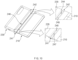
- FIG. 10 is a perspective view illustrating a cover for a foldable electronic device according to various embodiments.
- a guide rail 240 may be provided in a form in which opposites sides are open.
- a pen holder 250 may be mounted on a connecting portion 230 through a first end portion 241 or a second end portion 242 of the guide rail 240.
- a protruding portion 251 may enter the first end portion 241 of the guide rail 240 and may move in the second sliding direction S, or may enter the second end portion 242 of the guide rail 240 and may move in the first sliding direction S.
- the cover 200 illustrated in FIG. 10 may differ from the cover 200 illustrated in FIG. 6 in that the former does not include the second depression 245 of the guide rail 240 and the second protrusion 255 of the pen holder 250.
- a third depression 247 may be formed on the first end portion 241 of the guide rail 240.
- the third depression 247 may be recessed in the z-axis direction, and at least a portion of a third protrusion (not illustrated) that is formed on the protruding portion 251 of the pen holder 250 may be inserted into the third depression 247.
- the third protrusion may be substantially the same as the first protrusion 254, except that the third protrusion is formed on a third end portion 252 of the protruding portion 251 of the pen holder 250.
- the cover 200 in which the pen holder 250 is able to be inserted into the guide rail 240 in the opposite directions, may include the physical coupling structures provided on the opposite end portions of the guide rail 240 and the opposite end portions of the pen holder 250.
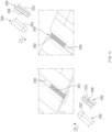
- FIG. 11 is a perspective view illustrating a cover for a foldable electronic device according to various embodiments.
- the cover 200 illustrated in FIG. 11 may differ from the cover 200 illustrated in FIG. 6 in that the former does not include the first depression 244, the first protrusion 254, the second depression 245, and the second protrusion 255.
- the cover 200 may include a coupling structure using magnets.
- a first magnet 261 may be disposed on a first end portion 241 of a guide rail 240
- a second magnet 262 may be disposed on a second end portion 242 of the guide rail 240.
- the pen holder 250 may be mounted on a connecting portion in various directions.
- a third end portion 252 of a protruding portion 251 of the pen holder 250 may enter the second end portion 242 of the guide rail 240 and may be inserted into the guide rail 240 in the first sliding direction S.
- a fourth end portion 253 of the protruding portion 251 of the pen holder 250 may enter the second end portion 242 of the guide rail 240 and may be inserted into the guide rail 240 in the first sliding direction S.
- the third end portion 252 of the protruding portion 251 of the pen holder 250 may enter the first end portion 241 of the guide rail 240 and may be inserted into the guide rail 240 in the second sliding direction S.
- the fourth end portion 253 of the protruding portion 251 of the pen holder 250 may enter the first end portion 241 of the guide rail 240 and may be inserted into the guide rail 240 in the second sliding direction S.
- the pen holder 250 may include a third magnet (not illustrated) that corresponds to the first magnet 261 of the guide rail 240 in a completely mounted state and a fourth magnet (not illustrated) that corresponds to the second magnet 262 of the guide rail 240 in the completely mounted state.
- the third magnet may be located on the third end portion 252 of the pen holder 250
- the fourth magnet may be located on the fourth end portion 253 of the pen holder 250.
- the corresponding magnets may form an attractive force.
- the pen holder 250 and the connecting portion may be stably fixed to each other by the attractive force of the corresponding magnets.
- one of the two magnets 261 and 262 included in the guide rail 240 may guide one of the two magnets included in the pen holder 250 (e.g., the second magnet 258 and the fourth magnet 259 of FIG. 9 ).
- FIG. 12 is a perspective view illustrating attachment and detachment of a pen to and from a cover for a foldable electronic device according to various embodiments.
- the pen 258 may be configured to be detachable from a pen holder 250.
- a first end portion 258a of the pen 258 that includes a pen tip 258c may be located in the pen holder 250 to protect the pen tip 258c in the state in which the pen 258 is mounted.
- the remaining portion of the pen 258 e.g., a second end portion 258b of the pen 258, may be exposed outside the pen holder 250.
- a user may remove the pen 258 from the pen holder 250 by holding and pulling the remaining portion.
- the pen holder 250 may include a second protruding portion 257 at least partially surrounding the second end portion 258b of the pen 258 in the state in which the pen 258 is mounted.
- the second protruding portion 257 may be provided in a curved shape along the second end portion 258b of the pen 258.
- the second protruding portion 257 may protrude from the lower surface of the pen holder 250 in the -z-axis direction.
- the second protruding portion 257 may make contact with the pen 258 in a process of attaching and detaching the pen 258.
- the pen 258 may be attached and detached in a direction inclined at a predetermined angle with respect to the sliding direction S.
- the second protruding portion 257 of the pen holder 250 may constrain the pen 258 in the sliding direction S such that the pen is not separated from the inside of the pen holder.
- the second protruding portion 257 may partially overlap the pen 258 when viewed in the sliding direction S.
- the electronic device may be one of various types of electronic devices.
- the electronic devices may include, for example, a portable communication device (e.g., a smartphone), a computer device, a portable multimedia device, a portable medical device, a camera, a wearable device, a home appliance, or the like. According to an embodiment of the disclosure, the electronic devices are not limited to those described above.
- each of such phrases as “A or B,” “at least one of A and B,” “at least one of A or B,” “A, B, or C,” “at least one of A, B, and C,” and “at least one of A, B, or C,” may include any one of, or all possible combinations of the items enumerated together in a corresponding one of the phrases.
- such terms as “1st” and “2nd,” or “first” and “second” may be used to simply distinguish a corresponding component from another, and does not limit the components in other aspect (e.g., importance or order).
- an element e.g., a first element
- the element may be coupled with the other element directly (e.g., wiredly), wirelessly, or via a third element.
- module may include a unit implemented in hardware, software, or firmware, and may interchangeably be used with other terms, for example, “logic,” “logic block,” “part,” or “circuitry”.
- a module may be a single integral component, or a minimum unit or part thereof, adapted to perform one or more functions.
- the module may be implemented in a form of an application-specific integrated circuit (ASIC).
- ASIC application-specific integrated circuit
- Various embodiments as set forth herein may be implemented as software (e.g., a program) including one or more instructions that are stored in a storage medium (e.g., internal memory or external memory) that is readable by a machine (e.g., an electronic device).
- a processor of the machine e.g., the electronic device
- the one or more instructions may include a code generated by a complier or a code executable by an interpreter.
- the machine-readable storage medium may be provided in the form of a non-transitory storage medium.
- non-transitory simply means that the storage medium is a tangible device, and does not include a signal (e.g., an electromagnetic wave), but this term does not differentiate between where data is semi-permanently stored in the storage medium and where the data is temporarily stored in the storage medium.
- a method may be included and provided in a computer program product.
- the computer program product may be traded as a product between a seller and a buyer.
- the computer program product may be distributed in the form of a machine-readable storage medium (e.g., compact disc read only memory (CD-ROM)), or be distributed (e.g., downloaded or uploaded) online via an application store (e.g., PlayStore TM ), or between two user devices (e.g., smart phones) directly. If distributed online, at least part of the computer program product may be temporarily generated or at least temporarily stored in the machine-readable storage medium, such as memory of the manufacturer's server, a server of the application store, or a relay server.
- CD-ROM compact disc read only memory
- an application store e.g., PlayStore TM
- two user devices e.g., smart phones
- each component e.g., a module or a program of the above-described components may include a single entity or multiple entities, and some of the multiple entities may be separately disposed in different components. According to various embodiments, one or more of the above-described components may be omitted, or one or more other components may be added. Alternatively or additionally, a plurality of components (e.g., modules or programs) may be integrated into a single component. In such a case, according to various embodiments, the integrated component may still perform one or more functions of each of the plurality of components in the same or similar manner as they are performed by a corresponding one of the plurality of components before the integration.
- operations performed by the module, the program, or another component may be carried out sequentially, in parallel, repeatedly, or heuristically, or one or more of the operations may be executed in a different order or omitted, or one or more other operations may be added.
Landscapes
- Engineering & Computer Science (AREA)
- Computer Networks & Wireless Communication (AREA)
- Signal Processing (AREA)
- General Engineering & Computer Science (AREA)
- Theoretical Computer Science (AREA)
- Human Computer Interaction (AREA)
- Physics & Mathematics (AREA)
- General Physics & Mathematics (AREA)
- Telephone Set Structure (AREA)
Applications Claiming Priority (2)
| Application Number | Priority Date | Filing Date | Title |
|---|---|---|---|
| KR1020210104115A KR20230022006A (ko) | 2021-08-06 | 2021-08-06 | 펜 홀더를 포함하는 폴더블 전자 장치용 커버 |
| PCT/KR2022/011178 WO2023013986A1 (ko) | 2021-08-06 | 2022-07-29 | 펜 홀더를 포함하는 폴더블 전자 장치용 커버 |
Publications (2)
| Publication Number | Publication Date |
|---|---|
| EP4338640A1 true EP4338640A1 (de) | 2024-03-20 |
| EP4338640A4 EP4338640A4 (de) | 2024-09-04 |
Family
ID=85153872
Family Applications (1)
| Application Number | Title | Priority Date | Filing Date |
|---|---|---|---|
| EP22853364.2A Pending EP4338640A4 (de) | 2021-08-06 | 2022-07-29 | Abdeckung für klappbare elektronische vorrichtung mit stifthalter |
Country Status (3)
| Country | Link |
|---|---|
| US (1) | US12301273B2 (de) |
| EP (1) | EP4338640A4 (de) |
| CN (1) | CN117794421A (de) |
Families Citing this family (7)
| Publication number | Priority date | Publication date | Assignee | Title |
|---|---|---|---|---|
| USD986845S1 (en) * | 2021-04-29 | 2023-05-23 | Samsung Electronics Co., Ltd. | Electronic device |
| USD986203S1 (en) * | 2021-04-29 | 2023-05-16 | Samsung Electronics Co., Ltd. | Electronic device |
| KR20230044673A (ko) * | 2021-09-27 | 2023-04-04 | 삼성전자주식회사 | 전자 장치의 커버 |
| USD1042388S1 (en) * | 2022-05-26 | 2024-09-17 | Samsung Electronics Co., Ltd. | Mobile electronic device |
| USD1042387S1 (en) * | 2022-05-26 | 2024-09-17 | Samsung Electronics Co., Ltd. | Mobile electronic device |
| CN220342350U (zh) * | 2023-06-28 | 2024-01-12 | 谢炳区 | 一种手机保护壳 |
| WO2025228276A1 (zh) * | 2024-04-30 | 2025-11-06 | 深圳市乐沐营销顾问有限公司 | 一种磁吸笔套及磁吸笔 |
Family Cites Families (26)
| Publication number | Priority date | Publication date | Assignee | Title |
|---|---|---|---|---|
| JP3225411B2 (ja) | 1992-09-18 | 2001-11-05 | 大日本印刷株式会社 | 艶消転写箔 |
| JP2004030096A (ja) * | 2002-06-25 | 2004-01-29 | Toshiba Corp | 携帯型電子機器 |
| JP5061602B2 (ja) | 2006-12-01 | 2012-10-31 | カシオ計算機株式会社 | 電子機器 |
| JP2013236729A (ja) | 2012-05-15 | 2013-11-28 | Casio Computer Co Ltd | 保護カバー |
| KR101331174B1 (ko) | 2013-08-19 | 2013-11-19 | (주)선운 이앤지 | 정확한 현지조사작업을 통한 수치지도 제작 시스템 |
| KR20150073747A (ko) * | 2013-12-23 | 2015-07-01 | 삼성전자주식회사 | 햅틱 피드백을 제공하기 위한 방법, 시스템 및 컴퓨터 판독 가능한 기록 매체. |
| US9327544B2 (en) | 2014-05-28 | 2016-05-03 | Alexander Ceruzzi | Stick-on stylus holder |
| WO2016022704A1 (en) | 2014-08-05 | 2016-02-11 | Bihn Hunter S | Diabetic medication delivery pen packet |
| KR101705084B1 (ko) | 2015-03-18 | 2017-02-09 | 최상효 | 휴대폰용 플립 케이스 |
| US9971379B2 (en) | 2015-08-26 | 2018-05-15 | Apple Inc. | Attachment features for an accessory device |
| JP6586341B2 (ja) | 2015-10-01 | 2019-10-02 | Dynabook株式会社 | 電子機器、ペン、及びペンの保持方法 |
| WO2017123899A1 (en) | 2016-01-15 | 2017-07-20 | Corning Incorporated | Foldable electronic device assemblies and cover elements for the same |
| JP6125703B1 (ja) | 2016-07-21 | 2017-05-10 | レノボ・シンガポール・プライベート・リミテッド | 固定構造およびそれを備えた情報処理システム |
| US10892625B1 (en) * | 2017-02-17 | 2021-01-12 | Apple Inc. | Cases and folios for carrying and charging accessories |
| US10739871B2 (en) * | 2017-04-27 | 2020-08-11 | Apple Inc. | Capacitive wireless charging systems |
| KR102763743B1 (ko) | 2019-07-29 | 2025-02-10 | 삼성전자주식회사 | 펜 수납부를 포함하는 커버 및 이를 포함하는 전자 장치 |
| CN210573497U (zh) | 2019-10-25 | 2020-05-19 | 李奎 | 一种新型ipad保护套 |
| KR102311151B1 (ko) | 2019-11-29 | 2021-10-13 | 김대용 | 화장품 케이스 |
| US11452311B1 (en) * | 2020-01-14 | 2022-09-27 | Christopher Johns | Phone case vape pen |
| US20210288687A1 (en) * | 2020-03-13 | 2021-09-16 | Jayno, LLC | Multi-functional padfolio |
| US11068023B1 (en) | 2020-09-03 | 2021-07-20 | Pioneer Square Brands, Inc. | Accessory coupling system |
| CN213043730U (zh) | 2020-11-05 | 2021-04-23 | 天之娇(厦门)皮革制品有限公司 | 一种可拆分式手机夹套 |
| USD986871S1 (en) * | 2020-12-01 | 2023-05-23 | Samsung Electronics Co., Ltd. | Case for electronic device |
| USD984428S1 (en) * | 2021-04-30 | 2023-04-25 | Samsung Electronics Co., Ltd. | Case for portable electronic device |
| CN220342350U (zh) * | 2023-06-28 | 2024-01-12 | 谢炳区 | 一种手机保护壳 |
| CN220457468U (zh) * | 2023-08-14 | 2024-02-06 | 深圳市维果时代科技有限公司 | 一种充分保护的折叠屏用外全包手机壳 |
-
2022
- 2022-07-29 CN CN202280054414.5A patent/CN117794421A/zh active Pending
- 2022-07-29 EP EP22853364.2A patent/EP4338640A4/de active Pending
- 2022-08-05 US US17/882,008 patent/US12301273B2/en active Active
Also Published As
| Publication number | Publication date |
|---|---|
| US20230037484A1 (en) | 2023-02-09 |
| CN117794421A (zh) | 2024-03-29 |
| US12301273B2 (en) | 2025-05-13 |
| EP4338640A4 (de) | 2024-09-04 |
Similar Documents
| Publication | Publication Date | Title |
|---|---|---|
| EP4338640A1 (de) | Abdeckung für klappbare elektronische vorrichtung mit stifthalter | |
| KR102716697B1 (ko) | 폴더블 전자 장치 및 그의 힌지 구조물 | |
| US11877406B2 (en) | Electronic device including display | |
| CN113439433B (zh) | 铰链模块及包括该铰链模块的可折叠电子装置 | |
| KR102344928B1 (ko) | 힌지 모듈 및 이를 포함하는 폴더블 전자 장치 | |
| KR102919929B1 (ko) | 플렉서블 디스플레이를 포함하는 전자 장치 | |
| US11188120B2 (en) | Foldable electronic device | |
| KR20180040968A (ko) | 플렉서블 디스플레이를 포함하는 폴더블 전자 장치 | |
| JP2019529991A (ja) | フレキシブルディスプレイ電子装置 | |
| JP7667950B2 (ja) | ヒンジカバーを含む電子装置 | |
| JP2013016767A (ja) | 携帯型電子機器の収納カバー | |
| US12449842B2 (en) | Strap structure connected to housing, and wearable electronic device comprising same | |
| KR20230022006A (ko) | 펜 홀더를 포함하는 폴더블 전자 장치용 커버 | |
| KR20160081450A (ko) | 하우징 결합 구조 및 그것을 갖는 전자 장치 | |
| US12547215B2 (en) | Electronic device including fixing member | |
| KR20230031100A (ko) | 서랍형 상자 | |
| KR20250061567A (ko) | 폴더블 전자 장치의 힌지부에 형성된 액세서리 체결 구조 및 스토퍼 구조 | |
| KR20250139698A (ko) | 이동식 디스플레이 구조를 포함하는 전자 장치 | |
| JP6368038B2 (ja) | 電子機器 | |
| JP6171823B2 (ja) | 端末システム及び携帯端末 | |
| EP4296194A1 (de) | Schubladenartige schachtel | |
| KR20250139697A (ko) | 전자 장치를 위한 크래들 | |
| KR20230033986A (ko) | 포장 상자 | |
| KR20250139696A (ko) | 전자 장치를 위한 밀착형 크래들 | |
| KR20240085097A (ko) | 전자 장치의 그립을 보조하기 위한 구조를 포함하는 케이스 |
Legal Events
| Date | Code | Title | Description |
|---|---|---|---|
| STAA | Information on the status of an ep patent application or granted ep patent |
Free format text: STATUS: THE INTERNATIONAL PUBLICATION HAS BEEN MADE |
|
| PUAI | Public reference made under article 153(3) epc to a published international application that has entered the european phase |
Free format text: ORIGINAL CODE: 0009012 |
|
| STAA | Information on the status of an ep patent application or granted ep patent |
Free format text: STATUS: REQUEST FOR EXAMINATION WAS MADE |
|
| 17P | Request for examination filed |
Effective date: 20231215 |
|
| AK | Designated contracting states |
Kind code of ref document: A1 Designated state(s): AL AT BE BG CH CY CZ DE DK EE ES FI FR GB GR HR HU IE IS IT LI LT LU LV MC MK MT NL NO PL PT RO RS SE SI SK SM TR |
|
| A4 | Supplementary search report drawn up and despatched |
Effective date: 20240806 |
|
| RIC1 | Information provided on ipc code assigned before grant |
Ipc: A45C 13/00 20060101ALI20240731BHEP Ipc: H04B 1/3888 20150101ALI20240731BHEP Ipc: A45C 15/00 20060101ALI20240731BHEP Ipc: A45C 11/00 20060101AFI20240731BHEP |
|
| DAV | Request for validation of the european patent (deleted) | ||
| DAX | Request for extension of the european patent (deleted) |