EP4338721A1 - Unité de traitement dentaire compatible avec différentes boîtes de connexion - Google Patents
Unité de traitement dentaire compatible avec différentes boîtes de connexion Download PDFInfo
- Publication number
- EP4338721A1 EP4338721A1 EP23196568.2A EP23196568A EP4338721A1 EP 4338721 A1 EP4338721 A1 EP 4338721A1 EP 23196568 A EP23196568 A EP 23196568A EP 4338721 A1 EP4338721 A1 EP 4338721A1
- Authority
- EP
- European Patent Office
- Prior art keywords
- dental
- base
- hydrogroup
- unit
- treatment unit
- Prior art date
- Legal status (The legal status is an assumption and is not a legal conclusion. Google has not performed a legal analysis and makes no representation as to the accuracy of the status listed.)
- Pending
Links
Images







Classifications
-
- A—HUMAN NECESSITIES
- A61—MEDICAL OR VETERINARY SCIENCE; HYGIENE
- A61G—TRANSPORT, PERSONAL CONVEYANCES, OR ACCOMMODATION SPECIALLY ADAPTED FOR PATIENTS OR DISABLED PERSONS; OPERATING TABLES OR CHAIRS; CHAIRS FOR DENTISTRY; FUNERAL DEVICES
- A61G12/00—Accommodation for nursing, e.g. in hospitals, not covered by groups A61G1/00 - A61G11/00, e.g. trolleys for transport of medicaments or food; Prescription lists
- A61G12/002—Supply appliances, e.g. columns for gas, fluid, electricity supply
- A61G12/007—Supply appliances, e.g. columns for gas, fluid, electricity supply mounted on the floor, e.g. tracks
-
- A—HUMAN NECESSITIES
- A61—MEDICAL OR VETERINARY SCIENCE; HYGIENE
- A61G—TRANSPORT, PERSONAL CONVEYANCES, OR ACCOMMODATION SPECIALLY ADAPTED FOR PATIENTS OR DISABLED PERSONS; OPERATING TABLES OR CHAIRS; CHAIRS FOR DENTISTRY; FUNERAL DEVICES
- A61G15/00—Operating chairs; Dental chairs; Accessories specially adapted therefor, e.g. work stands
- A61G15/14—Dental work stands; Accessories therefor
Definitions
- the present invention relates to dental treatment units, and in particular to a base and a hydrogroup for said units allowing an easy replacement of a dental treatment unit already installed in a dental practice with a new dental treatment unit.
- Dental treatment units have been industrially produced for several decades, and comprise a plurality of instruments allowing a dentist to administer dental therapies to a patient.
- they comprise a patient chair, a hydrogroup, a scialytic lamp, a dentist's board, an assistant's board generally provided with suction cannulas.
- said patient chair comprises a headrest.
- the two configurations a and b have been known for a long time in the art, too.
- US3650033A1 of Siemens AG shows a patient chair of the chair mounted type, wherein the hydrogroup is integrally connected to the patient chair through a connecting arm, while the patient chair is fixed to the floor.
- Figure 2 of US3650033A1 shows a patient chair 1 and a hydrogroup 10 connected through a connecting arm 35.
- a parallelogram arm 8 allows the rising and lowering of said patient chair 1, which thanks to its integral connections to the hydrogroup 10 through said arm 35, drags said hydrogroup 10 raising and lowering it with respect to the floor.
- DE1822226U of EMDA published in 1960 , describes a solution of the type b, i.e. a suspended chair dental treatment unit, with a hydrogroup fixed to the floor provided with a vertical movement for the patient chair with respect to the floor, well visible in Figure 2 of DE1822226U .
- Other known art documents are EP2086489A1 of Kaltenbach & Voigt, published in 2009 , and EP2526916A1 of Planmeca, published in 2012 .
- the unit is shiftable orbitally and laterally with respect to the chair so that the instrument center can be located in the correct position relative to the position of the headrest of the chair throughout the range of adjustment of the chair back.
- the invention described in this patent allows to move the hydrogroup (called dental unit 12) with respect to the patient chair 11, in order to obtain alternatively a first configuration wherein the hydrogroup is placed on the right of the patient seated in the chair or a second configuration wherein the hydrogroup is placed on the left of the patient seated in the chair.
- a movement on the horizontal plane of dental unit 12 with respect to the patient chair 11 is provided.
- vacuum connection 52 electric connection 53, compressed air connection 54, water connection 55, and a drain or waste connection 56, i.e. the well 51, is located under the base assembly 10, inside the outline of the patient chair 11.
- These connections must allow the movement of the dental unit 12 around the patient chair 11.
- a further feature is that, in case of fixed hydrogroup dental units, the patient chair can alternatively provide:
- Figures 1 show a chair mounted dental treatment unit presently produced by the applicant
- Figures 2 show a floor mounted dental treatment unit presently produced by the applicant
- Figures 3 show a suspended chair dental treatment unit presently produced by the applicant.
- Figures 2 show a floor mounted dental unit provided with a patient chair comprising two articulated portions, the first portion supporting patient's thighs and the second portion supporting patient's calves.
- the hydrogroup is a structural portion of the dental treatment unit, which generally allows to support the dental treatment unit portions different from patient chair, i.e. the assistant's board, the scialytic lamp, optionally the dentist's board, which in its turn supports a plurality of dental handpieces (dental syringe, micro-motor, turbine, polymerizing lamp, dental camera, etc.). Often the hydrogroup also supports a bowl and a water-to-cup spout.
- the hydrogroup is substantially a hollow structure housing reservoirs, electronic boards, piping and wiring. These components are hidden from view, so that the dental treatment unit shows a pleasing and reassuring look for patients.
- Said hydrogroup is substantially provided with the shape of a parallelepiped with six sides:
- the metallic frame of the hydrogroup can be likened to a boxed body, in fact its faces are actually its two top and lower bases. Its four lateral faces are open; there are provided just the edges of the boxed body.
- the metallic frame of the hydrogroup is closed and hidden from view by an aesthetic housing, generally made of a suitable plastic material.
- Patient chair must be connected to electric energy for its movements; dental handpieces generally need be fed with electric energy, compressed air and water; suction cannulas must be connected to a suction device. Moreover, the liquids coming from the dental treatment unit must be conveyed to sewer drain. Generally, under the floor there are provided systems providing the necessary feeds, and the drain of liquids. These systems generally come out from the floor in contiguous points, forming a connections box.
- connections box relates to the set of all the supplies (i.e. suction, compressed air, water, electric energy and drain) that are needed for the functioning of dental units, i.e. the piping and wiring providing said supplies in their point of emersion from the floor, which piping and wiring are typically placed inside a small area, called connections box.
- supplies i.e. suction, compressed air, water, electric energy and drain
- connections boxes are provided so as to arrive directly under the dental treatment unit; e.g. see US3524676A of Cocherell et al . In this way, they remain hidden from view, once the dental treatment unit is installed in a dental practice.
- the piping and wiring conveying suction, compressed air, water, electric energy and drain piping come out from said connections box, which generally lies on the floor; then their path continues in order to establish a connection to said dental treatment unit in a site called feeds entry point.
- the market of dental treatment units is a mature market, wherein the main part of dental treatment units, in a proportion of about 90/10, is acquired in order to replace a pre-existing dental treatment unit, already installed in a dental practice.
- Each manufacturer of dental treatment units provides its own characteristic arrangement of the internal organs of the hydrogroup, in particular with respect to the connections box. This allows to easily replace an already installed dental treatment unit with a new dental treatment unit provided with its connections box arranged in the same position.
- Aim of the present invention is providing a dental treatment unit allowing to easily replace an already installed dental treatment unit with a new one, even when the already installed dental treatment unit is provided with a different arrangement of said connections box.
- the present invention is applicable to dental units of the type chair mounted dental treatment unit and floor mounted dental treatment unit.
- the present invention reaches this aim by providing a base allowing the connection of the feeds entry point in the hydrogroup with all the main positions of the connections boxes known in the art. Moreover, each of the connections boxes is covered by a respective aesthetic housing hiding feed piping and wiring (for suction, compressed air, water, electric energy and drain) from the view, from their point of exit from the floor and for a portion of such piping and wiring. Said aesthetic housings are provided adjacent and in continuity with the aesthetic housing covering the base of patient chair, so as to form a visual-functional unit, preventing the running of free piping and wiring on the floor, which poses a serious danger for the safety of dental staff and patients.
- Said bases are provided in different embodiments according to the kind of dental treatment unit, as will be made clearer in the following.
- Each base is substantially a plate optionally in continuity with the base of the hydrogroup lying on the floor.
- Each embodiment allows the passage of piping and wiring above said base.
- said base cooperates with the structure of the hydrogroup. According to different cases, the ingress of piping and wiring is provided on the main side of the hydrogroup oriented toward the patient chair, or on the posterior short side of the hydrogroup, or on the front of the chair.
- the different kinds of bases are completed by specific aesthetic housings made of a suitable plastic material, aimed at covering the different connections boxes from view.
- a first advantage is easing and accelerating the replacement of a dental treatment unit already installed in a dental practice with a new one, by exploiting the already existing hydraulic/electric/pneumatic connections.
- a second advantage is the possibility of replacement without the need of masonry/hydraulic/electric/pneumatic works.
- the third advantage is the possibility of maintaining the same outline on the floor of the patient chair already installed in the dental practice, without the need to move the new dental treatment unit in order to connect it to the floor feeds already present. Therefore, for dental staff the room for manoeuvre remains the same.
- a fourth advantage is the improvement in safety for dental staff and patients, in that the aesthetic housings form a visual-functional continuity with the floor outline of the dental treatment unit, preventing the possibility of tripping in flying connections.
- a fifth advantage is that the aesthetic housings according to the invention are modular. According to the connections box already present in the dental practice, a housing can be chosen in order to obtain a dental treatment unit pleasing to the eye, but especially safe for dental staff and patients.
- FIGS 1A, 1B show a chair mounted dental treatment unit 10 that is part of the present production of the applicant.
- Said chair mounted dental treatment unit comprises: a patient chair 1, a hydrogroup 2, a bowl 3, a dentist's board 4, an assistant's board 5 and a headrest 9.
- the vertical movement of the patient chair 1 is performed through a pantograph mechanism placed in the base of patient chair 1, provided with a pantograph arm 6.
- the patient chair 1 and the hydrogroup 2 are integrally connected through a connecting arm 8 (visible in Figure 1B only), and therefore patient chair and hydrogroup rise and lower at the same time.
- FIGS 2A, 2B show a floor mounted dental treatment unit 20 that is part of the present production of the applicant.
- Said floor mounted dental treatment unit comprises: a patient chair 1, a hydrogroup 2, a bowl 3, a dentist's board 4, an assistant's board 5 and a headrest 9.
- the vertical movement of the patient chair 1 is performed through a pantograph mechanism placed in the base of patient chair 1, provided with a pantograph arm 6.
- the hydrogroup 2 remains stationary, while the patient chair 1 rises and lowers with respect to the floor and the hydrogroup.
- the patient chair 1 and the hydrogroup 2 are substantially independent.
- the chair 1 is provided with a support 11 for patient's thighs and a support 12 for patient's calves, articulated at the level of patient's knees.
- FIGS 3A, 3B show a suspended chair dental treatment unit 30 that is part of the present production of the applicant.
- Said suspended chair dental treatment unit comprises: a patient chair 1, a hydrogroup 2, a bowl 3, a dentist's board 4, an assistant's board 5 and a headrest 9.
- the vertical movement of the patient chair 1 is performed through a raising/lowering mechanism inside the hydrogroup 2, comprising a mechanism for raising and lowering the patient chair through an arm 7 (visible in Figure 3B only).
- the hydrogroup 2 remains stationary, while the patient chair 1 rises and lowers with respect to the hydrogroup 2 and the floor.
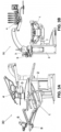
- Figure 4 shows a simplified axonometric view of a dental treatment unit 101 of a floor mounted dental unit according to the first embodiment of the present invention, comprising a patient chair 41 and a hydrogroup 42.
- Figure 4 shows the main alternative positions of the connections boxes C1, C2, C3 with respect to patient chair 41 and hydrogroup 42.
- just one of the shown connections boxes is present on the floor of the dental practice, and to this connections box the already installed dental treatment unit is connected.
- Figure 5 shows the second embodiment according to the present invention, with the main alternative positions of the connections boxes C1, C3 with respect to the patient chair 411, 412, 413 and hydrogroup 42.
- the patient chair is provided with a seat 412 articulated with a calf support 413 at the height of patient's knees.
- the calf support 413 In the position wherein both the backrest 411 and the calf support 413 are perpendicular to the floor, the calf support 413 must not collide against the housing of the chair base, and therefore the chair base must be provided with dimensions more reduced with respect to the first embodiment.
- Figure 6 shows the third embodiment according to the present invention, with the main alternative positions of the connections boxes C2, C3 with respect to the patient chair 41 and hydrogroup 42. As the hydrogroup 42 never touches the floor, in this embodiment the connection with the connections box C1 is not provided.
- connection box C3 As can be observed in Figures 4 , 5 , 6 , the positions of the different connections boxes are characteristic and markedly different. For instance, should a new dental treatment unit be connected to a connections box C3, masonry works would be needed in order to move the connections box. Alternatively, the new dental treatment unit should be translated in the space, but in the new position collisions might occur with dental practice walls or furniture. Alternatively, the connections box and the feeds entry point of the new dental treatment might be connected through external piping and wiring running freely on the floor, which are an obstacle and pose a danger for dental staff and patients.
- the present invention allows reaching the feeds entry point inside the hydrogroup 42 from any of the connections boxes C1 or C2 or C3 thanks to a base 511, 512, 513 according to the present invention.
- the placement of the different components inside the hydrogroup was made so as to allow the ingress of piping and wiring from alternative points, substantially placed on the posterior short side or on the internal main side of said hydrogroup or in front of the chair.
- Over said base there are provided specific aesthetic housings, allowing to cover the path of piping/wiring from the different connections boxes C1 or C2 or C3 to the feeds entry point.
- Said aesthetic housings are placed in continuity with the aesthetic housings covering the chair base or the hydrogroup, and therefore no free-running piping/wiring are provided, and anyway the housings are in a visual-functional continuity with the dental treatment unit.
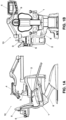
- FIGS 7A, 7B , 7C show the hydrogroup without its aesthetic housing 42 allowing to appreciate the path of the piping/wiring coming from C1, C2 and C3 connections boxes, respectively, and the shape of the base 511 according to the first embodiment.
- Said hydrogroup comprises a known metallic frame 52 having a parallelepiped shape.
- Said metallic frame 52 is a frame supporting the functional internal components (not shown reservoirs, piping, electric boards, wiring), which is in its turn integral with said base 511.
- the connections box C1 piping and wiring enter into the hydrogroup by the posterior short side
- the connections boxes C2 and C3 the same piping and wiring enter into the hydrogroup by the internal main side.
- internal main side the hydrogroup side oriented toward the patient chair is meant.
- Said base 511 which remains the same for all connections boxes C1, C2, C3, is provided with a substantial T-shape, with the base 551 of said T adjacent to the base 43 of said metallic structure 52, a posterior arm 552 and an anterior arm 558.
- Said anterior arm 558 is provided with two prongs, a first prong 556 and a second prong 557, between which there is provided a recess 555.
- the central portion 553 of said T is provided with a slot 554.
- Figure 7A shows the position of the connections box C1, which is adjacent to the posterior short side of the metallic structure 52, and in use is covered by a specific aesthetic housing, forming a visual-functional unit.
- Figure 7B shows the position of the connections box C3, which is placed in front of the base of patient chair 41, but nearer to the hydrogroup, and in use is covered by an aesthetic housing, forming a visual-functional unit. From the connections box C3, piping/wiring follow a path leading them to the feeds entry point inside said hydrogroup.
- Figure 7C shows the position of the connections box C2, which is placed in front of the base of patient chair 41 too, and in use is covered by an aesthetic housing, forming a visual-functional unit.
- the connections box C2 is placed inside said recess 555 provided between said two prongs 556 and 557. From the connections box C2, piping/wiring follow a path leading them to the feeds entry point inside said hydrogroup.
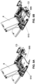
- FIGS 8A, 8B show the hydrogroup without the aesthetic housings 42 and allow to appreciate the path of piping/wiring coming from connections boxes C1 and C3, respectively, and the shape of the base 512 according to the second embodiment.
- Said hydrogroup comprises the known metallic frame 52 having a parallelepiped shape.
- Said metallic frame 52 is a frame supporting the functional internal components (not shown reservoirs, piping, electric boards, wiring), which is in its turn integral with said base 512.
- Said base 512 which remains the same for both connections boxes C1 and C3, in its rear position is provided with the same shape of the base 511. Due to the fact that the base must support a patient chair provided with an articulated calf support 413 (see Figure 5 ), the front portion of the T is missing, i.e. the front arm 558 is missing.
- the base 551 of the T is adjacent to said hydrogroup base 43, and there is provided the rear arm 552.
- the central portion 553 of the T is provided with said slot 554.
- Figure 8A shows the position of the connections box C1, which is adjacent to the rear short side of the metallic structure 52, and in use is covered by a specific aesthetic housing, forming a visual-functional unit.
- Figure 8B shows the connections box C3, which is placed in front of the base of patient chair 41, but nearer to the hydrogroup, and in use is covered by a specific aesthetic housing, forming a visual-functional unit. From the connections box C3, piping/wiring follow a path leading them to the feeds entry point inside said hydrogroup.
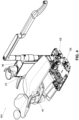
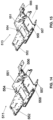
- Figures 9A, 9B show the base of the patient chair 41 without the aesthetic housing and allow to appreciate the path of piping/wiring coming from connections boxes C2 and C3, respectively, and the shape of the base 513 according to the third embodiment.
- the hydrogroup never touches the ground. Therefore, the position C1 of the connections box is not provided.
- the piping/wiring coming from the connections box C2 and C3 follow a path (visible in Figure 9C ) that provides, in its first portion downside the connections box, penetrating inside the housing covering the pantograph arm 6 supporting the patient chair 41, then passing inside the arm 8 connecting the patient chair 41 and the hydrogroup 42, and finally reaching the hydrogroup on its internal main side.
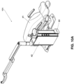
- FIG 10A shows the dental treatment unit 101 as it appears from the outside when connected to the connections box C1 ( Figure 7A ).
- the point of emergence of piping/wiring from the floor is covered by a specific housing 61, which is provided only in the case when the dental unit 101 is actually connected to a connections box C1. If the dental unit 101 is connected to a connections box C2 or C3, the aesthetic housing 61 is not provided.
- Figure 10B shows the dental treatment unit 101 as it appears from the outside when it is connected to the connections box C1 or C2 or C3.
- An aesthetic housing 441 covers the basis of the patient chair 41.
- a further aesthetic housing 63 covers the portion 556 of the base 511, and is always provided.
- the two aesthetic housings 441 and 63 are adjacent; on the adjacent walls of the housings 441 and 63 there are provided apertures allowing the passage of piping/wiring. On the floor there are no free piping/wiring.
- Figures 11A and 11B show the dental treatment unit 102 as it appears from the outside when it is connected to the connections box C1 ( Figure 8A ).
- An aesthetic housing 442 completely covers the base 512.
- Figure 11A shows the dental treatment unit 102 in a front view when it is connected to the connections box C1.
- Figure 11B shows that the point of emergence of piping/wiring from the floor is covered by a specific housing 62, which is provided only when said unit 102 is actually connected to a connections box C1. If the dental unit 102 is connected to a connections C3, the housing 62 is not provided.
- Figures 12A and 12B show the dental treatment unit 102 as it appears from the outside when it is connected to the connections box C3 ( Figure 8B ).
- Figure 12A shows the dental unit 102 in a front view.
- the aesthetic housing 442 completely covers the base 512, and is of reduced dimensions in order to allow the calf support 413 to reach its extreme position wherein it is perpendicular to the floor.
- An aesthetic housing 64 covers the connections box C3, and is in a visual-functional continuity with the housing 442.
- the aesthetic housing 442 is pre-set in order to connect it to the aesthetic housing 64: there are provided some apertures for the passage of piping/wiring.
- Figure 12B that is a rear view, shows that the aesthetic housing 61 is not provided, as in this case is useless.
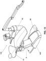
- Figure 13 shows the dental treatment unit 103 as it appears from the outside when it is connected to the connections box C2 or C3.
- An aesthetic housing 65 covers the portion 556 of the base 513, and is in a visual-functional continuity with the housing 443. From the outside it is not possible to tell whether the dental unit 103 is connected to a connections box C2 or C3, as the aesthetic housings 443 and 65 do not change.
- the aesthetic housing 443 is pre-set with apertures for the passage of piping/wiring in order to connect it to the aesthetic housing 65.
- the front wall of said housing 441, 442 is continuous.
- the wall of the housing 443 is continuous, while the housing 42 covering the hydrogroup is pre-set for the passage of piping/wiring.
- the wall of the aesthetic cover 441, 443 covering the chair base is provided for allowing the passage of connecting piping/wiring coming from the connections box C3.
- the bases 511, 512, 513 are components produced in metallic carpentry, which undergo suitable working for fixing the carpentry components that form the supporting structure 52 of the hydrogroup, preferably made of metal.
- the base 43 of the hydrogroup 42 and the bases 511, 512 form one piece: this allows to obtain a dental treatment unit with more stability.
- the method according to the present invention comprises the following steps:
Landscapes
- Health & Medical Sciences (AREA)
- Life Sciences & Earth Sciences (AREA)
- Animal Behavior & Ethology (AREA)
- General Health & Medical Sciences (AREA)
- Public Health (AREA)
- Veterinary Medicine (AREA)
- Nursing (AREA)
- Accommodation For Nursing Or Treatment Tables (AREA)
Applications Claiming Priority (1)
| Application Number | Priority Date | Filing Date | Title |
|---|---|---|---|
| IT102022000018648A IT202200018648A1 (it) | 2022-09-13 | 2022-09-13 | Unità di trattamento odontoiatrico compatibile con diverse cassette allacciamenti |
Publications (1)
| Publication Number | Publication Date |
|---|---|
| EP4338721A1 true EP4338721A1 (fr) | 2024-03-20 |
Family
ID=84331342
Family Applications (1)
| Application Number | Title | Priority Date | Filing Date |
|---|---|---|---|
| EP23196568.2A Pending EP4338721A1 (fr) | 2022-09-13 | 2023-09-11 | Unité de traitement dentaire compatible avec différentes boîtes de connexion |
Country Status (2)
| Country | Link |
|---|---|
| EP (1) | EP4338721A1 (fr) |
| IT (1) | IT202200018648A1 (fr) |
Citations (9)
| Publication number | Priority date | Publication date | Assignee | Title |
|---|---|---|---|---|
| DE1822226U (de) | 1960-09-17 | 1960-11-24 | Emda | Zahnaerztlicher hoehenverstellbarer behandlungsstuhl. |
| DE1932324U (de) | 1965-12-04 | 1966-02-10 | Kaltenbach & Voigt | Zahnaerztliches einheitsgeraet. |
| US3524676A (en) | 1967-08-04 | 1970-08-18 | Francis E Cocherell | Dental apparatus |
| US3578379A (en) | 1967-12-28 | 1971-05-11 | Pennwalt Corp | Adjustable chair |
| US3650033A (en) | 1968-10-26 | 1972-03-21 | Siemens Ag | Dental treatment units |
| EP0100491A2 (fr) | 1982-08-02 | 1984-02-15 | Siemens Aktiengesellschaft | Fauteuil dentaire |
| EP0895769A2 (fr) | 1997-07-30 | 1999-02-10 | Kaltenbach & Voigt Gmbh & Co. | Fauteuil de soins médicaux ou dentaires |
| EP2086489A1 (fr) | 2006-10-31 | 2009-08-12 | Kaltenbach & Voigt GmbH | Fauteuil dentaire |
| EP2526916A1 (fr) | 2006-11-21 | 2012-11-28 | Planmeca Oy | Appareil de soins dentaires intégré |
-
2022
- 2022-09-13 IT IT102022000018648A patent/IT202200018648A1/it unknown
-
2023
- 2023-09-11 EP EP23196568.2A patent/EP4338721A1/fr active Pending
Patent Citations (9)
| Publication number | Priority date | Publication date | Assignee | Title |
|---|---|---|---|---|
| DE1822226U (de) | 1960-09-17 | 1960-11-24 | Emda | Zahnaerztlicher hoehenverstellbarer behandlungsstuhl. |
| DE1932324U (de) | 1965-12-04 | 1966-02-10 | Kaltenbach & Voigt | Zahnaerztliches einheitsgeraet. |
| US3524676A (en) | 1967-08-04 | 1970-08-18 | Francis E Cocherell | Dental apparatus |
| US3578379A (en) | 1967-12-28 | 1971-05-11 | Pennwalt Corp | Adjustable chair |
| US3650033A (en) | 1968-10-26 | 1972-03-21 | Siemens Ag | Dental treatment units |
| EP0100491A2 (fr) | 1982-08-02 | 1984-02-15 | Siemens Aktiengesellschaft | Fauteuil dentaire |
| EP0895769A2 (fr) | 1997-07-30 | 1999-02-10 | Kaltenbach & Voigt Gmbh & Co. | Fauteuil de soins médicaux ou dentaires |
| EP2086489A1 (fr) | 2006-10-31 | 2009-08-12 | Kaltenbach & Voigt GmbH | Fauteuil dentaire |
| EP2526916A1 (fr) | 2006-11-21 | 2012-11-28 | Planmeca Oy | Appareil de soins dentaires intégré |
Also Published As
| Publication number | Publication date |
|---|---|
| IT202200018648A1 (it) | 2024-03-13 |
Similar Documents
| Publication | Publication Date | Title |
|---|---|---|
| CN102639029B (zh) | 用于家具的可伸缩立柱 | |
| US7195219B2 (en) | Modular dental chair equipment mounting system | |
| EP4338721A1 (fr) | Unité de traitement dentaire compatible avec différentes boîtes de connexion | |
| CN105937260B (zh) | 具有冲洗附盖的座便器 | |
| GB2169014A (en) | Service outlet system | |
| JP5871869B2 (ja) | 統合歯科治療装置 | |
| EP4338720B1 (fr) | Unité de traitement dentaire compatible avec différentes boîtes de connexion | |
| CN213607956U (zh) | 一种膝关节康复训练椅 | |
| CN206651963U (zh) | 用于牙科治疗单元的模块化结构 | |
| US20200107984A1 (en) | Adjustable Surgical Chair | |
| JPH08289909A (ja) | 供給ユニット | |
| CN101583333A (zh) | 一体化牙科护理装置 | |
| CN108261221B (zh) | 一种下颌骨截骨导板 | |
| JPH077934Y2 (ja) | 歯科椅子の患者唾液吸引ノズル支持用スイングアーム | |
| US3295206A (en) | Dental equipment | |
| US3418714A (en) | Device for variable height positioning of treatment appliances on dental equipment | |
| WO2022049729A1 (fr) | Buse d'aspiration sous vide pour traitement dentaire, vide pour traitement dentaire et dispositif de traitement dentaire | |
| CN201026239Y (zh) | 肢体治疗支架 | |
| CN215535572U (zh) | 一种用于青光眼治疗的眼部给药装置 | |
| KR101705669B1 (ko) | L자형 의료가스 베드 콘솔 유닛 | |
| CN211094697U (zh) | 一种可升降手术终端 | |
| FI130935B1 (en) | Within mouth scanning arrangement | |
| EP0116184A1 (fr) | Système de réglage en hauteur et en longueur d'un châlit | |
| USD1057952S1 (en) | Medical imaging stand | |
| CN217525477U (zh) | 一种口腔正畸开口器用调节装置 |
Legal Events
| Date | Code | Title | Description |
|---|---|---|---|
| PUAI | Public reference made under article 153(3) epc to a published international application that has entered the european phase |
Free format text: ORIGINAL CODE: 0009012 |
|
| STAA | Information on the status of an ep patent application or granted ep patent |
Free format text: STATUS: THE APPLICATION HAS BEEN PUBLISHED |
|
| AK | Designated contracting states |
Kind code of ref document: A1 Designated state(s): AL AT BE BG CH CY CZ DE DK EE ES FI FR GB GR HR HU IE IS IT LI LT LU LV MC ME MK MT NL NO PL PT RO RS SE SI SK SM TR |
|
| STAA | Information on the status of an ep patent application or granted ep patent |
Free format text: STATUS: REQUEST FOR EXAMINATION WAS MADE |
|
| 17P | Request for examination filed |
Effective date: 20240809 |
|
| RBV | Designated contracting states (corrected) |
Designated state(s): AL AT BE BG CH CY CZ DE DK EE ES FI FR GB GR HR HU IE IS IT LI LT LU LV MC ME MK MT NL NO PL PT RO RS SE SI SK SM TR |
|
| STAA | Information on the status of an ep patent application or granted ep patent |
Free format text: STATUS: EXAMINATION IS IN PROGRESS |
|
| 17Q | First examination report despatched |
Effective date: 20250917 |