EP4338775A1 - Sac de respiration artificielle manuel comprenant un dispositif venturi - Google Patents
Sac de respiration artificielle manuel comprenant un dispositif venturi Download PDFInfo
- Publication number
- EP4338775A1 EP4338775A1 EP22196394.5A EP22196394A EP4338775A1 EP 4338775 A1 EP4338775 A1 EP 4338775A1 EP 22196394 A EP22196394 A EP 22196394A EP 4338775 A1 EP4338775 A1 EP 4338775A1
- Authority
- EP
- European Patent Office
- Prior art keywords
- oxygen
- gas
- conduct
- upstream
- rear member
- Prior art date
- Legal status (The legal status is an assumption and is not a legal conclusion. Google has not performed a legal analysis and makes no representation as to the accuracy of the status listed.)
- Granted
Links
Images



Classifications
-
- A—HUMAN NECESSITIES
- A61—MEDICAL OR VETERINARY SCIENCE; HYGIENE
- A61M—DEVICES FOR INTRODUCING MEDIA INTO, OR ONTO, THE BODY; DEVICES FOR TRANSDUCING BODY MEDIA OR FOR TAKING MEDIA FROM THE BODY; DEVICES FOR PRODUCING OR ENDING SLEEP OR STUPOR
- A61M16/00—Devices for influencing the respiratory system of patients by gas treatment, e.g. ventilators; Tracheal tubes
- A61M16/10—Preparation of respiratory gases or vapours
- A61M16/12—Preparation of respiratory gases or vapours by mixing different gases
- A61M16/122—Preparation of respiratory gases or vapours by mixing different gases with dilution
- A61M16/125—Diluting primary gas with ambient air
- A61M16/127—Diluting primary gas with ambient air by Venturi effect, i.e. entrainment mixers
-
- A—HUMAN NECESSITIES
- A61—MEDICAL OR VETERINARY SCIENCE; HYGIENE
- A61M—DEVICES FOR INTRODUCING MEDIA INTO, OR ONTO, THE BODY; DEVICES FOR TRANSDUCING BODY MEDIA OR FOR TAKING MEDIA FROM THE BODY; DEVICES FOR PRODUCING OR ENDING SLEEP OR STUPOR
- A61M16/00—Devices for influencing the respiratory system of patients by gas treatment, e.g. ventilators; Tracheal tubes
- A61M16/0057—Pumps therefor
- A61M16/0084—Pumps therefor self-reinflatable by elasticity, e.g. resuscitation squeeze bags
-
- A—HUMAN NECESSITIES
- A61—MEDICAL OR VETERINARY SCIENCE; HYGIENE
- A61M—DEVICES FOR INTRODUCING MEDIA INTO, OR ONTO, THE BODY; DEVICES FOR TRANSDUCING BODY MEDIA OR FOR TAKING MEDIA FROM THE BODY; DEVICES FOR PRODUCING OR ENDING SLEEP OR STUPOR
- A61M16/00—Devices for influencing the respiratory system of patients by gas treatment, e.g. ventilators; Tracheal tubes
- A61M16/10—Preparation of respiratory gases or vapours
- A61M16/1005—Preparation of respiratory gases or vapours with O2 features or with parameter measurement
-
- A—HUMAN NECESSITIES
- A61—MEDICAL OR VETERINARY SCIENCE; HYGIENE
- A61M—DEVICES FOR INTRODUCING MEDIA INTO, OR ONTO, THE BODY; DEVICES FOR TRANSDUCING BODY MEDIA OR FOR TAKING MEDIA FROM THE BODY; DEVICES FOR PRODUCING OR ENDING SLEEP OR STUPOR
- A61M16/00—Devices for influencing the respiratory system of patients by gas treatment, e.g. ventilators; Tracheal tubes
- A61M16/20—Valves specially adapted to medical respiratory devices
- A61M16/201—Controlled valves
-
- A—HUMAN NECESSITIES
- A61—MEDICAL OR VETERINARY SCIENCE; HYGIENE
- A61M—DEVICES FOR INTRODUCING MEDIA INTO, OR ONTO, THE BODY; DEVICES FOR TRANSDUCING BODY MEDIA OR FOR TAKING MEDIA FROM THE BODY; DEVICES FOR PRODUCING OR ENDING SLEEP OR STUPOR
- A61M16/00—Devices for influencing the respiratory system of patients by gas treatment, e.g. ventilators; Tracheal tubes
- A61M16/20—Valves specially adapted to medical respiratory devices
- A61M16/208—Non-controlled one-way valves, e.g. exhalation, check, pop-off non-rebreathing valves
- A61M16/209—Relief valves
-
- A—HUMAN NECESSITIES
- A61—MEDICAL OR VETERINARY SCIENCE; HYGIENE
- A61M—DEVICES FOR INTRODUCING MEDIA INTO, OR ONTO, THE BODY; DEVICES FOR TRANSDUCING BODY MEDIA OR FOR TAKING MEDIA FROM THE BODY; DEVICES FOR PRODUCING OR ENDING SLEEP OR STUPOR
- A61M16/00—Devices for influencing the respiratory system of patients by gas treatment, e.g. ventilators; Tracheal tubes
- A61M16/0057—Pumps therefor
- A61M16/0078—Breathing bags
-
- A—HUMAN NECESSITIES
- A61—MEDICAL OR VETERINARY SCIENCE; HYGIENE
- A61M—DEVICES FOR INTRODUCING MEDIA INTO, OR ONTO, THE BODY; DEVICES FOR TRANSDUCING BODY MEDIA OR FOR TAKING MEDIA FROM THE BODY; DEVICES FOR PRODUCING OR ENDING SLEEP OR STUPOR
- A61M16/00—Devices for influencing the respiratory system of patients by gas treatment, e.g. ventilators; Tracheal tubes
- A61M16/04—Tracheal tubes
-
- A—HUMAN NECESSITIES
- A61—MEDICAL OR VETERINARY SCIENCE; HYGIENE
- A61M—DEVICES FOR INTRODUCING MEDIA INTO, OR ONTO, THE BODY; DEVICES FOR TRANSDUCING BODY MEDIA OR FOR TAKING MEDIA FROM THE BODY; DEVICES FOR PRODUCING OR ENDING SLEEP OR STUPOR
- A61M16/00—Devices for influencing the respiratory system of patients by gas treatment, e.g. ventilators; Tracheal tubes
- A61M16/06—Respiratory or anaesthetic masks
-
- A—HUMAN NECESSITIES
- A61—MEDICAL OR VETERINARY SCIENCE; HYGIENE
- A61M—DEVICES FOR INTRODUCING MEDIA INTO, OR ONTO, THE BODY; DEVICES FOR TRANSDUCING BODY MEDIA OR FOR TAKING MEDIA FROM THE BODY; DEVICES FOR PRODUCING OR ENDING SLEEP OR STUPOR
- A61M16/00—Devices for influencing the respiratory system of patients by gas treatment, e.g. ventilators; Tracheal tubes
- A61M16/20—Valves specially adapted to medical respiratory devices
- A61M16/201—Controlled valves
- A61M16/202—Controlled valves electrically actuated
- A61M16/203—Proportional
- A61M16/205—Proportional used for exhalation control
-
- A—HUMAN NECESSITIES
- A61—MEDICAL OR VETERINARY SCIENCE; HYGIENE
- A61M—DEVICES FOR INTRODUCING MEDIA INTO, OR ONTO, THE BODY; DEVICES FOR TRANSDUCING BODY MEDIA OR FOR TAKING MEDIA FROM THE BODY; DEVICES FOR PRODUCING OR ENDING SLEEP OR STUPOR
- A61M16/00—Devices for influencing the respiratory system of patients by gas treatment, e.g. ventilators; Tracheal tubes
- A61M16/20—Valves specially adapted to medical respiratory devices
- A61M16/208—Non-controlled one-way valves, e.g. exhalation, check, pop-off non-rebreathing valves
-
- A—HUMAN NECESSITIES
- A61—MEDICAL OR VETERINARY SCIENCE; HYGIENE
- A61M—DEVICES FOR INTRODUCING MEDIA INTO, OR ONTO, THE BODY; DEVICES FOR TRANSDUCING BODY MEDIA OR FOR TAKING MEDIA FROM THE BODY; DEVICES FOR PRODUCING OR ENDING SLEEP OR STUPOR
- A61M2202/00—Special media to be introduced, removed or treated
- A61M2202/02—Gases
- A61M2202/0208—Oxygen
-
- A—HUMAN NECESSITIES
- A61—MEDICAL OR VETERINARY SCIENCE; HYGIENE
- A61M—DEVICES FOR INTRODUCING MEDIA INTO, OR ONTO, THE BODY; DEVICES FOR TRANSDUCING BODY MEDIA OR FOR TAKING MEDIA FROM THE BODY; DEVICES FOR PRODUCING OR ENDING SLEEP OR STUPOR
- A61M2205/00—General characteristics of the apparatus
- A61M2205/33—Controlling, regulating or measuring
- A61M2205/3331—Pressure; Flow
- A61M2205/3337—Controlling, regulating pressure or flow by means of a valve by-passing a pump
Definitions
- the present invention relates to a manual artificial respiration bag, such as manual resuscitation devices/systems, resuscitators or the like, comprising a venturi device that can be used for providing a respiratory gas, namely oxygen or an air/oxygen mixture, to a person, i.e. a patient, especially a person in state of cardiac arrest or any other patient in need of being artificially ventilated by such a manual artificial respiration bag.
- a manual artificial respiration bag such as manual resuscitation devices/systems, resuscitators or the like
- a venturi device that can be used for providing a respiratory gas, namely oxygen or an air/oxygen mixture
- a manual resuscitation bag can be used for providing a respiratory gas, such as air, oxygen or a mixture thereof, to a person in need of a respiratory assistance, typically a patient.
- a respiratory gas such as air, oxygen or a mixture thereof
- Classical manual artificial respiration bags are used for providing a respiratory gas, such as air or an air/O 2 mixture, to a patient, during his/her transportation or transfer from a first place, such as an operation room or a radiotherapy room, to a second place, such as a recovery room or a bedroom, or vice versa. Examples of such bags are given by US-A-3,063,620 , US-A-2017/0157348 , US-A-4,501,271 or US-A-2,834,339 . However, such classical manual artificial respiration bags are not suitable for providing a respiratory gas to a person in state of cardiac arrest as they are not compatible or well-adapted with the cardiac massage that is done on the person.
- a respiratory gas such as air or an air/O 2 mixture
- manual artificial respiration bags also called manual resuscitation bags
- manual resuscitation bags have been specifically designed for artificially ventilating a person in state of cardiac arrest, with air or an air/O 2 mixture, while thoracic compressions (TC), i.e. successive compressions and decompressions, are exerted by a rescuer on the thoracic cage of said person for restoring gas exchanges in the lungs and a blood circulation in the body and toward the organs, especially to the brain of the patient.
- manual resuscitation bags are given by WO2019/001751 , WO2019/001752 , WO2017/096286 , WO2015/041396 , WO2005/035065 and EP-A-0743075 .
- EP-A-3884982 and EP-A-3884983 disclose improved multifunctional manual artificial respiration bags that can be used in various situations, such as transportation/transfer of patients, persons in state of cardiac arrest that undergo thoracic compressions...
- Such an improved manual artificial respiration bag comprises an air entry and an oxygen entry for providing both air and oxygen to the bag, thereby allowing delivering either air, oxygen or mixtures thereof to the patient in need thereof.
- a spontaneous circulation i.e. of a blood circulation perfusing the body resulting from the resumption of a cardiac rhythm
- the FiO 2 i.e. the quantity of oxygen that is provided by the manual respiration bag, for taking into account the variation of the oxygen saturation of the patient, namely the concentration of oxygen into the blood of the patient.
- the amount of oxygen provided to the patients is random, especially for amounts less than 100 vol.%.
- a goal of the present invention is to provide an improved manual artificial respiration bag allowing a more accurate control of the proportion of oxygen provided to the patients, especially when the proportion of oxygen has to be less than 100 vol.%, typically less than 80 vol.%, for instance of about 50 vol.%, especially in case of ROSC while ventilating a person having had a cardiac arrest.
- a solution according to the present invention concerns a manual artificial respiration bag comprising:
- venturi device of the manual respiration bag can comprise of one or several of the following additional features:
- a manual respiration bag according to the present invention can comprise of one or several of the following additional features:
- Figure 1 represents a side view of an embodiment of a manual artificial respiration bag 1 according to the present invention.
- Said manual artificial respiration bag 1 comprises a deformable bag 10, i.e. flexible hollow bag or reservoir, comprising an inner volume 13 for receiving a respiratory gas, i.e. oxygen or a mixture of air and oxygen, a gas inlet 11 for allowing the gas to enter into said inner volume 13, and a gas outlet 12 for allowing the gas to exit said inner volume 13 of the deformable bag 10.
- a respiratory gas i.e. oxygen or a mixture of air and oxygen
- a gas inlet 11 for allowing the gas to enter into said inner volume 13
- a gas outlet 12 for allowing the gas to exit said inner volume 13 of the deformable bag 10.
- a user In use, a user, typically a rescuer, e.g. a physician or similar, can exert a manual-pressure on the deformable bag 10, i.e. manually squeeze it, for deforming it and thus expelling the gas contained therein, via the gas outlet 12, toward a patient in need thereof, such as a person in a state of cardiac arrest that should be artificially ventilated.
- a rescuer e.g. a physician or similar
- the deformable bag 10 is typically made of flexible material, typically a polymer material and has an inner volume 13 of preferably less than 2 L (i.e. when filled with water).
- the manual artificial respiration bag 1 further comprises an upstream conduct element 20 fluidly connected to the gas inlet 11 of the deformable bag 10, and a downstream conduct element 30 fluidly connected to the gas outlet 12 of the deformable bag 10.
- Both upstream and downstream conduct elements 20, 30 comprise a generally-tubular shape comprising a lumen, i.e. inner passage, for receiving and conveying the gas flow.
- the upstream conduct element 20 comprises a PEP exhaust valve 22 fluidly communicating with the ambient atmosphere for venting gas (i.e. any over-pressure) to the atmosphere when the gas pressure, into the upstream conduct element 20, i.e. in its lumen, exceeds a given pressure threshold.
- gas i.e. any over-pressure
- the PEP exhaust valve 22 prevents gas overpressures in the deformable bag 10 and/or in the upstream conduct element 20 fluidly connected to the gas inlet 4 of the deformable bag 2.
- the PEP exhaust valve 22 comprises a rotatable member 22-1, such as a rotating knob or the like, actuatable by a user, namely a rescuer, a valve body and means for setting a desired pressure threshold including pressure adjusting means arranged into the valve body.
- Said pressure adjusting means can comprise a piston head, a spring element, such as a cylindrical spring, and a valve seat cooperating with the piston head for adjusting the pressure threshold.
- the PEP exhaust valve 22 further comprises several markings corresponding to several settable pressure values, typically overpressure values of between 0 and 30 cm H 2 O.
- the rotatable member 22-1 further comprises an inner axially-projecting bulb, which cooperates with the pressure adjusting means for adjusting the pressure threshold.
- Such a PEP exhaust valve 22 has a known architecture.
- the upstream conduct element generally comprises an air admission valve in fluid communication with the ambient atmosphere, for providing ambient air to the upstream conduct element, and an oxygen port for connecting an oxygen source thereto, such as an oxygen cylinder, for providing additional oxygen to the upstream conduct element and forming an oxygen/air mixture therein.
- the upstream conduct element 20 comprises a unique gas entry port 21, i.e. a common and unique inlet, that is used for providing the desired gases to the lumen of the upstream conduct element 20, namely either pure oxygen or an oxygen/air mixture.
- both desired gases i.e. pure oxygen or an oxygen/air mixture
- a venturi device 50 that is arranged in the gas entry port 21 of the manual artificial respiration bag according to the present invention, as shown in Figure 1 .
- a venturi device 50 is arranged so as to be in fluid communication with the unique gas entry port 21 for delivering either pure oxygen or an air/oxygen mixture to the upstream conduct element 20 of the manual artificial respiration bag according to the present invention.
- An embodiment of the venturi device 50 equipping the manual artificial respiration bag 1 according to the invention is detailed below.
- an oxygen source such as an oxygen gas cylinder (not shown) or any other O 2 source
- a gas line 60 comprising a gas connector 60-1 or plug, such as a flexible hose or the like, as shown in Figure 1 .
- the gas connector 60-1 is arranged at a free end of the gas line 60 and fluidly connected to connector means 138 arranged on the oxygen feeding conduct 135 of the venturi device 50 for providing oxygen gas to the venturi device 50, as explained below.
- the manual artificial respiration bag according to the present invention of Figure 1 further comprises an upstream one-way valve (not visible) that is arranged into the upstream conduct element 20 between the deformable bag 10 and the PEP exhaust valve 22 and/or the unique gas entry port 21 in fluid communication with the venturi device 50.
- an upstream one-way valve (not visible) that is arranged into the upstream conduct element 20 between the deformable bag 10 and the PEP exhaust valve 22 and/or the unique gas entry port 21 in fluid communication with the venturi device 50.
- the upstream one-way valve is configured for allowing the flow of respiratory gas provided by the unique gas entry port 21 and the venturi device 50 to pass through said upstream one-way valve only toward the deformable bag 10, i.e. to circulate in the direction of the deformable bag 10.
- a downstream one-way valve (not shown) is arranged into the downstream conduct element 30, i.e. into its lumen, for instance between the over-pressure valve 31 (when present), such as a pressure relief valve, and an exhaust valve 35, and is configured for allowing a flow of respiratory gas provided by the deformable bag 10 to pass through said downstream one-way valve only toward the patient.
- the role of the downstream one-way valve is to control the way that the gas circulates into the downstream one-way valve 30.
- Said downstream one-way valve can comprise for instance a valve support arranged into the downstream conduct element 30 and a flexible valve body, which can have an umbrella-shape comprising a disk-shape body and a rod element integral with said disk-shape body, whereas the valve-support comprises a support orifice, the rod element of the flexible valve body traversing said support orifice of the valve-support, i.e. the rod element is positioned into the support orifice so as to be guided.
- the gas exits the deformable bag 10, via the gas outlet 12, upon manual pressures/squeezing operated by a rescuer, such as a physician or any other medical staff member, on the flexible peripheral wall(s) of the deformable bag 10, and then travels in the downstream conduct element 30, i.e. into its lumen, toward the patient.
- a rescuer such as a physician or any other medical staff member
- the bag 10 is immediately refilled by "fresh" gas, i.e. oxygen or an air/oxygen mixture, provided by the venturi device 50 and/or a flexible gas reservoir 40 that replaces the quantity or volume of gas that has been provided to the downstream conduct element 30.
- fresh gas i.e. oxygen or an air/oxygen mixture
- the upstream conduct element 20 further comprises a reservoir port 20-1 for fluidly connecting a flexible gas reservoir 40 thereto, as shown in Figure 1 , such as a flexible polymer pocket or the like.
- a flexible gas reservoir 40 is used for storing a part of the gas provided by the unique gas entry port 21 and the venturi device 50, and providing gas when required, e.g. for refilling the the deformable bag 10.
- the flexible gas reservoir 40 constitutes a gas buffer or the like.
- downstream conduct elements 30 may also optionally comprise an over-pressure valve 31 (in some embodiments, such an over-pressure valve may be not necessary) for venting to the atmosphere any overpressure in said downstream conduct elements 30, i.e. in its lumen.
- an over-pressure valve 31 in some embodiments, such an over-pressure valve may be not necessary
- the upstream conduct element 20 and/or the downstream conduct elements 30 are made of polymer material(s), such as plastic material(s) or the like.
- the respiratory gas such as air or an air/O 2 mixture
- the downstream conduct element 30 that is fluidly connected to the gas outlet 12 of the deformable bag 10
- a respiratory interface such as a facial mask, a laryngeal mask, an endotracheal tube or the like that fluidly connected to an interface port 32 arranged in the downstream conduct element 30, as illustrated in Figure 1 , for instance by means of a ball-head hollow connector or any other suitable tubular-connector.
- the interface port 32 of the downstream conduct element 30 can be arranged on a gas delivery conduct or the like, branched to the downstream conduct element 30.
- the manual resuscitation bag 1 can comprise a handle (not shown) or the like for manually transporting it, for instance when used in a mobile emergency vehicle, such as an ambulance, a firefighting vehicle or the like.
- a mobile emergency vehicle such as an ambulance, a firefighting vehicle or the like.
- the downstream conduct elements 30 further includes an exhaust valve 35 with an exhaust port 36 for venting to the atmosphere, the CO 2 -enriched gases expired by the patient and/or coming out of the lungs of the patient.
- mobile port-closing means 37 actuatable by the rescuer, cooperating with the exhaust port 36 of the exhaust valve 35 for at least partially closing said exhaust port 36 thereby controlling the flow of gas passing through the exhaust port 36 of the exhaust valve 35, especially CO 2 -enriched gas coming out of the patient lungs.
- Said mobile port-closing means 37 are arranged on or comprise a mobile support-structure actuatable by the user. Said mobile port-closing means 37 are configured for at least partially closing the exhaust port 36 of the exhaust valve 35 in response to an actuation of the mobile support-structure by the user, typically to a rotation, pivoting or translation of the support-structure.
- the mobile adjusting member 37 is rotatable, i.e. can be turned clockwise or counter-clockwise by a rescuer, and is further coupled to or arranged on the downstream conduct element 30.
- a pivoting or translating element for instance a rigid curtain or the like, directly arranged on the exhaust valve 35.
- said mobile port-closing means 37 cooperate with the exhaust port 36 of the exhaust valve 35 for partially closing said exhaust port 36 thereby limiting the flow of gas passing through said exhaust port 36.
- the port-closing means 37 can be omitted or removed from the exhaust port 36 so that said exhaust port 36 is free, i.e. widely open, thereby letting a maximum gas exiting through said exhaust port 36, i.e. be vented to the atmosphere.
- the mobile port-closing means 37 can comprise a closing flap or wall or the like that can partially occlude the exhaust port 36, when desired, for controlling the gas flow passage, i.e. section area, or the like and hence controlling the pressure prevailing in the downstream conduct element 30, such as a expiratory pressure.
- the closing flap or wall carried by the support-structure that can be actuated by the rescuer, typically rotated/turned (i.e. pivot), between several angular positions comprising a first angular position (i.e. "fully open” position) wherein it does not occlude/close the exhaust port 36 of the exhaust valve 35 so that a maximum flow of gas can be released to the atmosphere through said exhaust port 36, for instance when the patient is ventilated with the bag 1, and a second angular position (i.e. "closed” position) wherein it does occlude/close almost all of the exhaust port 36 of the exhaust valve 35, for instance about 90 or 95% of it (i.e.
- the closing flap of the mobile port-closing means 37 can be fixed to or carried by the outer wall of the rotatable support-structure.
- said closing flap or wall can be made in one-piece, for instance molded in one-piece, with the support-structure.
- the mobile port-closing means 37 can be fixed to another part of the manual resuscitation bag 1, in particular of the downstream conduct 30, i.e. not associated to or integral with the rotatable adjusting member 37.
- a flow-restriction element such as a disk element carrying a calibrated orifice, can also be arranged into the downstream conduct element 30 for regulating the flow of gas provided by the flexible reservoir 10.
- manual resuscitation bag 1 can also comprise additional elements or features.
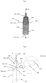
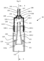
- Figures 2 to 8 are different views of an embodiment of a venturi device 50 equipping a manual artificial respiration bag 1 according to the invention.
- the venturi device 50 comprises an inner venturi nozzle 120 that is in fluid communication with the upstream conduct element 20, via the gas entry port 21 arranged in said upstream conduct element 20, for providing the desired gas to the upstream conduct element 20, namely oxygen or a mixture of oxygen and air, as explained below.
- Figure 2 is a general view of a preferred embodiment of a venturi device 50 forming part of a manual artificial respiration bag 1 according to the present invention, showing in transparency the two main parts or sub-units of the venturi device 50 cooperating together, namely a main body 110 and a rear member 130, i.e. a gas-providing member, unit or part, which are mobile with respect to the other for controlling, i.e. selecting, the type of gas, i.e. desired gas, that has to be provided by the venturi device 50 to the deformable reservoir 10, namely either oxygen or an air/oxygen mixture.
- a main body 110 and a rear member 130 i.e. a gas-providing member, unit or part
- the main body 110 comprises an inner compartment 111 comprising a venturi nozzle 120 co-axially arranged in said inner compartment 111.
- the inner compartment 111 is divided in 2 sub-compartments by an inner wall 139, namely an inlet chamber 112 or upstream chamber, and an outlet chamber 113 or downstream chamber.
- the inner compartment 111 has a circular section, i.e. a cylindrical inner-shape
- the inner wall 139 has a ring-shape.
- the venturi nozzle 120 is arranged through the inner wall 139 that divides the inner compartment 111. It comprises a nozzle inlet 121 located on the side of the inlet chamber 112 and a nozzle outlet 122 located on the side of the outlet chamber 113, preferably in said outlet chamber 113.
- An inner nozzle channel 120-1, 120-2 is arranged between the nozzle inlet 121 and the nozzle outlet 122 for conveying the gas from the nozzle inlet 121 to the nozzle outlet 122.
- the venturi nozzle 120 comprises two successive channel portions forming the inner nozzle channel 120-1, 120-2 comprising a first channel portion 120-1 comprising the nozzle inlet 121 and having an inner cylindrical shape, and a second channel portion comprising the nozzle outlet 122 and having an inner divergent shape.
- the first channel portion 120-1 fluidly connects the nozzle inlet 121 to the second channel portion 120-2.
- the first channel portion 120-1 can have an inner convergent shape.
- the second channel portion 120-2 is arranged between the first channel portion 120-1 and the nozzle outlet 122. As it comprises an inner divergent shape or profile, its inner diameter gradually increases toward the nozzle outlet 122.
- the gas i.e. O 2 or air/O 2
- the main body 110 of the venturi device 50 has an axially-elongated shape, i.e. along axis (XX), as shown in Fig. 7 (sectional view), in particular a tubular outer shape, e.g. cylindrical outer shape, but other outer shapes are possible.
- the outer diameter of the main body 110 is of about between 25 and 40 mm, and its length is of about between 60 and 110 mm.
- the inlet chamber 112 of the main body 110 is in fluid communication with the mixing chamber 133 of the rear member 130 that constitutes the second main part or sub-unit of the venturi device 50.
- the rear member 130 has a generally cup-like shape, but other shapes are possible. It comprises an (or several) oxygen inlet 131 for providing oxygen and one or preferably several air inlets 132 for providing air, and the mixing chamber 133 for mixing therein air with oxygen provided by said oxygen inlet 131.
- the oxygen inlet(s) 131 and the air inlets 132, for instance four air inlets 132, arranged around the oxygen inlet 131 are better visible in the top view 160 of Fig. 6 .
- the venturi device 50 comprises the main body 110 comprising the venturi nozzle 120 arranged therein, the oxygen inlet 131 for providing oxygen, the air inlets 132 for providing air, and the mixing chamber 133 for mixing the flow of oxygen provided by the oxygen inlet 131 and the flow of ambient air provided by air inlets 132, so as to provide a desired gas, namely only oxygen or an air/oxygen mixture, when such a mixture is required.
- the venturi device 50 further comprises gas selection means for selecting oxygen provided by the oxygen inlet 131 or an air/oxygen mixture provided by the mixing chamber 133 as a desired gas to be provided to the venturi nozzle 120, and subsequently to the upstream conduct element 20, through the gas entry port 21, of the manual artificial respiration bag 1 according to the present invention.
- the gas selection means comprise the rear member 130 that is mobile with respect to the main body 110, upon actuation of a user, between (at least) a closed position (as shown in Fig. 7B ), wherein the rear member 130 cooperates directly with the venturi nozzle 120 for providing oxygen to the venturi nozzle 120, in particular to the inner nozzle channel 120-1, 120-2 of the venturi nozzle 120, and an open position (as shown in Fig. 7A ), wherein the rear member 130 cooperates with the venturi nozzle 120 for providing the air/oxygen mixture obtained in the mixing chamber 133 to the inner nozzle channel 120-1, 120-2 of the venturi nozzle 120.
- the inner nozzle channel 120-1, 120-2 of the venturi nozzle 120 is fed with oxygen only, i.e. "pure" oxygen
- the inner nozzle channel 120-1, 120-2 of the venturi nozzle 120 is fed with a mixture of air and oxygen, i.e. an air/oxygen mixture, coming from the mixing chamber 133 of the rear member 130.
- the rear member 130 is preferably not mobile in translation, but rather according to a helicoidal motion with respect to the main body 110, as shown in Figures 4 & 5 , for allowing the user, i.e. rescuer, medical staff member or the like, to manually select and set a desired open or closed position.
- a helicoidal motion means that the selection or setting of the closed or open position is made by the user when turning, clockwise or counterclockwise (cf. Fig. 4 & 5 ), the rear member 130 with respect to the main body 110 of the venturi device 50, or vice versa, thereby obtaining an helicoidal motion of those parts 110, 130, one with respect to the other. In other words, it screws in and out.
- the rear member 130 is helicoidally mobile with respect to the main body 110 when manually-turned clockwise or counterclockwise by a user.
- the rear member 130 can be also mobile only in translation with respect to the main body 110 for selecting the closed or the open position. Nevertheless, a helicoidal motion is preferred as it avoids wrong or accidental motions of the mobile parts.
- the main body 110 of the venturi device 50 comprises one or several elongated grooves 140 and the rear member 130 comprises one or several guiding members 50, or vice versa, preferably two elongated grooves 140 cooperating with two guiding members 150, as shown in Fig. 2-7A & B , each guiding member 150 being inserted into one of said elongated grooves 140, thereby cooperating with said elongated grooves 140 for guiding the helicoidal motion of the rear member 130 with respect to the main body 110, while the rear member 130 is actuated by a user, i.e. manually rotated/turned around axis (XX), with respect to the main body 110, or vice versa.
- a user i.e. manually rotated/turned around axis (XX), with respect to the main body 110, or vice versa.
- the two elongated grooves 140 are arranged in the peripheral wall 142 of the main body 110 and are diametrically-opposed, whereas the two guiding members 150 are diametrically-oppositely arranged on the peripheral surface of the rear member 130.
- the elongated grooves 140 constitute guides or paths that guide the guiding members 150, when the venturi device 50 is manually-actuated by the user, i.e. turned clockwise or counterclockwise as shown in Fig. 4 & 5 .
- the elongated grooves 140 are preferably elongated slots 141 traversing the peripheral wall 142 of the main body 110, in particular the inlet chamber 112 of the main body 110, i.e. traversing slots 141 or the like.
- the guiding members 150 comprise or are protrusions 151 arranged on the peripheral outer surface 134 of the rear member 130, preferably the peripheral outer surface 134 of the front portion 130-1 of the rear member 130.
- Each protrusion 151 forms a dent, a pin, a finger or any other similar small structure projecting away from the peripheral outer surface 134 of the rear member 130.
- the elongated grooves 140 of the main body 110 in particular the slots 141, comprise a curved linear portion 147, i.e. a linear segment, arranged in the cylindrical peripheral wall 142 of the main body 110, which is terminated by two end lodgings 146A, 146B that correspond to the open (146B) and closed (146A) positions of the venturi device 50.
- the end lodgings 146A, 146B are sized and configured for receiving or lodging the guiding members 150, in particular the protrusions 151.
- the protrusions 151 cooperate with the end lodgings 146A, 146B for setting the venturi device 50 in the open (146B) or closed (146A) positions as illustrated in Figure 3 , thereby providing an oxygen/air mixture or only oxygen to the manual artificial respiration bag 1 of the present invention, via the inner venturi nozzle 120 and through the gas entry port 21 of the upstream conduct element 20, which are in fluid communication.
- each elongated groove 140 preferably of each elongated slot 141, is diagonally-arranged in the peripheral wall 142 of the main body 110, namely in the peripheral wall of the inlet chamber 112 of the main body 110 as shown in Fig. 4-6 .
- each end lodging 146A, 146B an abutment 145 as visible in Figure 3 , that is located at a site of junction 148 between of the curved linear portion 147 of the elongated grooves/slots 140, 141 and each end lodgings 146A, 146B.
- said abutments 145 can be little wall structures or similar projecting in each end lodging 146A, 146B.
- the role of those abutments 145 is to block or to retain the protrusions 151 in the end lodgings 146A, 146B for setting the venturi device 50 in the open (146B) or in the closed (146A) positions as illustrated in Figures 3-6 .
- those abutments 145 are safety blocks or the like.
- the venturi device 50 in the closed position with the two protrusions 151 lodged and blocked in the first end lodgings 146A corresponding to said closed position, as illustrated in Fig. 4 (left side), and has to be set in the open position
- the user actuates, namely rotates counterclockwise, for instance the rear member 130 so that the two protrusions 151 are helicoidally guided by the two slots 141, in particular the linear curved portions of the slots 141, until they reach the second end lodgings 146B corresponding to the open position, as illustrated in Fig. 4 (right side).
- the two protrusions 151 are blocked and retained therein by the abutments 145, as better shown in Fig. 3 , that shows an enlarged view of a second end lodging 146B with a protrusion 151 retained therein by an abutment 145.
- the abutments 45 prohibit that the protrusions 151 accidentally get out of the end lodgings 146A, 146B thereby ensuring stable open or closed positions of the venturi device 50.
- the elongated grooves 140 e.g. the elongated slots 141, each have a length of about between 20 and 30 mm, and/or a width of about between 3.5 and 5 mm.
- the guiding members 150 e.g. the protrusions 151, have a height of about between 1.5 and 3 mm.
- a front portion 130-1 of the rear member 130 is inserted into at least a part of the inlet chamber 112 of the main body 110.
- said front portion 130-1 of the rear member 130 is externally cylindrical, i.e. tubular, and at least a part 112-1 of the inlet chamber 112 of the main body 110 is internally cylindrical, so that said cylindrical front portion 130-1 of the rear member 130 can be rotate in said cylindrical part 112-1 of the inlet chamber 112 of the main body 110.
- the outer diameter Do of said front portion 130-1 of the rear member 130 is less but approximately equal to the inner diameter Di of the cylindrical part 112-1 of the inlet chamber 112 of the main body 110 so that the helicoidal motion is allowed, i.e. Do ⁇ Di, according to the embodiment shown in Figures 2-8 .
- the front portion 130-1 of the rear member 130 delimits at least a part of the mixing chamber 133 used for mixing the oxygen flow and the air flow(s), when required.
- the rear member 130 comprises a hollow tubular portion 130-2 closed at one end by a blind bottom 130-3, i.e. it has a cup-like shape or similar as better shown in Fig. 8 .
- the other end of the tubular portion 130-2 is open toward the inlet chamber 112 of the main body 110.
- the rear member 130 has an outer diameter of about between 20 and 40 mm, and a length of about between 40 and 70 mm.
- the rear member 130 comprises, i.e. is traversed by, an oxygen feeding conduct 135 comprising an outer conduct portion 135-2, i.e. upstream portion, and an inner conduct portion 135-1, i.e. downstream portion, for providing oxygen gas to the venturi device 50.
- the oxygen feeding conduct 135 is axially-arranged (XX axis) through the blind bottom 130-3 of the rear member 130, i.e. it traverses the blind bottom 130-3.
- the outer conduct portion 135-2 of the oxygen feeding conduct 135 comprises the oxygen inlet 131, at its distal free end, and is located outside of the venturi device 50.
- the inner conduct portion 135-1 of the oxygen feeding conduct 135 comprises an oxygen delivery port 136 for providing oxygen located at its free end.
- the oxygen feeding conduct 135 is axially-traversed by a lumen 137 for conveying oxygen gas from the oxygen inlet 131 to the oxygen delivery port 136 thereby providing oxygen coming from an external oxygen source, such as a gas cylinder, a gas line or any other O 2 source.
- an external oxygen source such as a gas cylinder, a gas line or any other O 2 source.
- the outer conduct portion 135-2 of the oxygen feeding conduct 135 also comprises connector means 138, such as a specific outer design, for fluidly connecting the oxygen line 60 thereto, as shown in Fig. 1 , that is fed by an external oxygen source (not shown), such as an oxygen gas cylinder or an oxygen wall-plug fed by a gas network.
- an external oxygen source such as an oxygen gas cylinder or an oxygen wall-plug fed by a gas network.
- the inner conduct portion 135-1 of the oxygen feeding conduct 135 is arranged so as to axially-project into the mixing chamber 133, whereas the outer conduct portion 135-2 of the oxygen feeding conduct 135 is arranged so as to axially-project outwardly of the rear member, i.e. outside of it.
- the oxygen feeding conduct 135 is in fluid communication, in particular via the lumen 137 of the inner and outer conduct portions 135-1, 135-2, with the mixing chamber 133, when the rear member 130 is in the open position as shown in Fig. 7A and 8 , for mixing air and oxygen, and providing such an O 2 /air mixture to the venturi nozzle 120.
- the oxygen feeding conduct 135 is in fluid communication, in particular via the lumen 137, with the inner nozzle channel 120-1, 120-2 of the venturi nozzle 120, when the rear member 130 is in the closed position as shown in Fig. 7B .
- the proximal free end of the inner conduct portion 135-1 of the oxygen feeding conduct 135 penetrates in the inner nozzle channel 120-1, 120-2 of the venturi nozzle 120, through the nozzle inlet 121, to deliver oxygen directly into the venturi nozzle 120, subsequently to the upstream conduct element 20, via the gas entry port 21, of the manual artificial respiration bag 1 according to the invention, as shown in Fig. 1 .
- the improved manual artificial respiration bag 1 of the present invention it is possible to operate a more accurate control of the proportion of oxygen provided to the patient, especially when the proportion of oxygen has to be less than 100 vol.%, typically less than 80 vol.%, for instance of about 50 vol.%, especially in case of ROSC while ventilating a person having had a cardiac arrest.
- the venturi device integrated in the manual respiration bag 1 of the invention can provide at least two accurate and precise levels of FiO 2 for ventilating persons suffering from a cardiac arrest or from another respiratory pathology or medical condition requiring at least two different amounts of oxygen, i.e. various FiO 2 , in particular a first amount of 100 vol% of oxygen, i.e. pure oxygen flow, and a second (or more) amount of oxygen that is less than 100 vol.%, resulting from the dilution of oxygen with ambient air in the mixing chamber 133 of the venturi device, for instance a quantity of oxygen of about 50 vol%.
- various FiO 2 in particular a first amount of 100 vol% of oxygen, i.e. pure oxygen flow, and a second (or more) amount of oxygen that is less than 100 vol.%, resulting from the dilution of oxygen with ambient air in the mixing chamber 133 of the venturi device, for instance a quantity of oxygen of about 50 vol%.
- the venturi system is designed for delivering a fixed amount of oxygen in the air/oxygen mixture obtained in the mixing chamber 133.
- the dimensions of the air inlet 132, the nozzle inlet 121 and nozzle outlet 136 for instance can be chosen and set to get the desired FiO 2 level, for instance a FiO 2 level of 50 vol.%.
- the dilution rate is controlled by controlling or adjusting the amount of air passing through the mixing chamber 133 by venturi effect, which depends on the O 2 flow.
- the FiO 2 will remain stable, for instance a FiO 2 of 50 vol.%.
- a manual artificial respiration bag 1 can be used in various situations, for instance for resuscitating a person in state of cardiac arrest or the like, or for ventilation a person during transportation from one place to another place, in the field, in hospital, at the patient's home, in emergency vehicles or in any other place.
Landscapes
- Health & Medical Sciences (AREA)
- Pulmonology (AREA)
- Emergency Medicine (AREA)
- Engineering & Computer Science (AREA)
- Anesthesiology (AREA)
- Biomedical Technology (AREA)
- Heart & Thoracic Surgery (AREA)
- Hematology (AREA)
- Life Sciences & Earth Sciences (AREA)
- Animal Behavior & Ethology (AREA)
- General Health & Medical Sciences (AREA)
- Public Health (AREA)
- Veterinary Medicine (AREA)
- Critical Care (AREA)
- Respiratory Apparatuses And Protective Means (AREA)
Priority Applications (3)
| Application Number | Priority Date | Filing Date | Title |
|---|---|---|---|
| EP22196394.5A EP4338775B1 (fr) | 2022-09-19 | 2022-09-19 | Sac de respiration artificielle manuel comprenant un dispositif venturi |
| CA3207872A CA3207872A1 (fr) | 2022-09-19 | 2023-07-28 | Sac de respiration artificielle manuel comprenant un dispositif venturi |
| US18/370,180 US20240091471A1 (en) | 2022-09-19 | 2023-09-19 | Manual artificial respiration bag comprising a venturi device |
Applications Claiming Priority (1)
| Application Number | Priority Date | Filing Date | Title |
|---|---|---|---|
| EP22196394.5A EP4338775B1 (fr) | 2022-09-19 | 2022-09-19 | Sac de respiration artificielle manuel comprenant un dispositif venturi |
Publications (2)
| Publication Number | Publication Date |
|---|---|
| EP4338775A1 true EP4338775A1 (fr) | 2024-03-20 |
| EP4338775B1 EP4338775B1 (fr) | 2026-04-01 |
Family
ID=83362554
Family Applications (1)
| Application Number | Title | Priority Date | Filing Date |
|---|---|---|---|
| EP22196394.5A Active EP4338775B1 (fr) | 2022-09-19 | 2022-09-19 | Sac de respiration artificielle manuel comprenant un dispositif venturi |
Country Status (3)
| Country | Link |
|---|---|
| US (1) | US20240091471A1 (fr) |
| EP (1) | EP4338775B1 (fr) |
| CA (1) | CA3207872A1 (fr) |
Citations (18)
| Publication number | Priority date | Publication date | Assignee | Title |
|---|---|---|---|---|
| US2834339A (en) | 1955-12-14 | 1958-05-13 | Bennett Respiration Products I | Positive pressure breathing apparatus |
| US3063620A (en) | 1959-01-06 | 1962-11-13 | British Oxygen Co Ltd | Self-expandable bag |
| US3262446A (en) * | 1963-11-18 | 1966-07-26 | Air Shields | Resuscitator |
| US3913607A (en) * | 1974-05-07 | 1975-10-21 | Hudson Oxygen Therapy Sales Co | Oxygen dilution apparatus |
| US4501271A (en) | 1981-10-13 | 1985-02-26 | John William Spear | Resuscitator |
| US4886055A (en) * | 1988-01-22 | 1989-12-12 | Hoppough John M | Nebulizer device |
| EP0743075A2 (fr) | 1995-05-16 | 1996-11-20 | Willy Rüsch Ag | Ballon d'insufflateur manuel |
| GB2407043A (en) * | 2003-03-06 | 2005-04-20 | Intersurgical Ltd | Adjustable venturi device for mixing gases for inhalation |
| WO2005035065A1 (fr) | 2003-09-11 | 2005-04-21 | Advanced Circulatory Systems, Inc. | Dispositif de reanimation a ballon et valve pour le traitement de l'hypotension, du traumatisme cranien et de l'arret cardiaque |
| WO2015041396A1 (fr) | 2013-09-22 | 2015-03-26 | (주)웰텍 | Ballon manuel de réanimation d'urgence comprenant un dispositif mesurant la quantité d'air inhalé |
| BE1023576B1 (fr) * | 2016-04-29 | 2017-05-09 | Frédéric DUPREZ | Insufflateur manuel a fraction inspiree d'oxygene constante |
| US20170157348A1 (en) | 2015-12-03 | 2017-06-08 | Capnia, Inc. | Resuscitation bag |
| US20180333555A1 (en) * | 2017-05-22 | 2018-11-22 | Vayu Global Health Innovations, LLC | Adjustable Ambient Air-Oxygen Blender |
| WO2019001751A1 (fr) | 2017-06-27 | 2019-01-03 | Air Liquide Sante (International) | Ballon de réanimation comportant une soupape d'échappement en pep compatible avec des compressions thoraciques |
| WO2019001752A1 (fr) | 2017-06-27 | 2019-01-03 | Air Liquide Sante (International) | Ballon de réanimation avec conduit de dérivation compatible avec des compressions thoraciques |
| US20210205566A1 (en) * | 2020-01-03 | 2021-07-08 | Aeon Research And Technology, Inc. | Gas delivery venturi devices |
| EP3884983A1 (fr) | 2020-03-25 | 2021-09-29 | Air Liquide Medical Systems | Sac de respiration artificielle manuel multifonctionnel |
| EP3884982A1 (fr) | 2020-03-25 | 2021-09-29 | Air Liquide Medical Systems | Sac de respiration artificielle manuel comportant des moyens de réglage de la résistance à l'écoulement coopérant avec une soupape unidirectionnelle |
-
2022
- 2022-09-19 EP EP22196394.5A patent/EP4338775B1/fr active Active
-
2023
- 2023-07-28 CA CA3207872A patent/CA3207872A1/fr active Pending
- 2023-09-19 US US18/370,180 patent/US20240091471A1/en active Pending
Patent Citations (19)
| Publication number | Priority date | Publication date | Assignee | Title |
|---|---|---|---|---|
| US2834339A (en) | 1955-12-14 | 1958-05-13 | Bennett Respiration Products I | Positive pressure breathing apparatus |
| US3063620A (en) | 1959-01-06 | 1962-11-13 | British Oxygen Co Ltd | Self-expandable bag |
| US3262446A (en) * | 1963-11-18 | 1966-07-26 | Air Shields | Resuscitator |
| US3913607A (en) * | 1974-05-07 | 1975-10-21 | Hudson Oxygen Therapy Sales Co | Oxygen dilution apparatus |
| US4501271A (en) | 1981-10-13 | 1985-02-26 | John William Spear | Resuscitator |
| US4886055A (en) * | 1988-01-22 | 1989-12-12 | Hoppough John M | Nebulizer device |
| EP0743075A2 (fr) | 1995-05-16 | 1996-11-20 | Willy Rüsch Ag | Ballon d'insufflateur manuel |
| GB2407043A (en) * | 2003-03-06 | 2005-04-20 | Intersurgical Ltd | Adjustable venturi device for mixing gases for inhalation |
| WO2005035065A1 (fr) | 2003-09-11 | 2005-04-21 | Advanced Circulatory Systems, Inc. | Dispositif de reanimation a ballon et valve pour le traitement de l'hypotension, du traumatisme cranien et de l'arret cardiaque |
| WO2015041396A1 (fr) | 2013-09-22 | 2015-03-26 | (주)웰텍 | Ballon manuel de réanimation d'urgence comprenant un dispositif mesurant la quantité d'air inhalé |
| US20170157348A1 (en) | 2015-12-03 | 2017-06-08 | Capnia, Inc. | Resuscitation bag |
| WO2017096286A1 (fr) | 2015-12-03 | 2017-06-08 | Capnia Inc. | Ballon de réanimation |
| BE1023576B1 (fr) * | 2016-04-29 | 2017-05-09 | Frédéric DUPREZ | Insufflateur manuel a fraction inspiree d'oxygene constante |
| US20180333555A1 (en) * | 2017-05-22 | 2018-11-22 | Vayu Global Health Innovations, LLC | Adjustable Ambient Air-Oxygen Blender |
| WO2019001751A1 (fr) | 2017-06-27 | 2019-01-03 | Air Liquide Sante (International) | Ballon de réanimation comportant une soupape d'échappement en pep compatible avec des compressions thoraciques |
| WO2019001752A1 (fr) | 2017-06-27 | 2019-01-03 | Air Liquide Sante (International) | Ballon de réanimation avec conduit de dérivation compatible avec des compressions thoraciques |
| US20210205566A1 (en) * | 2020-01-03 | 2021-07-08 | Aeon Research And Technology, Inc. | Gas delivery venturi devices |
| EP3884983A1 (fr) | 2020-03-25 | 2021-09-29 | Air Liquide Medical Systems | Sac de respiration artificielle manuel multifonctionnel |
| EP3884982A1 (fr) | 2020-03-25 | 2021-09-29 | Air Liquide Medical Systems | Sac de respiration artificielle manuel comportant des moyens de réglage de la résistance à l'écoulement coopérant avec une soupape unidirectionnelle |
Also Published As
| Publication number | Publication date |
|---|---|
| US20240091471A1 (en) | 2024-03-21 |
| CA3207872A1 (fr) | 2024-03-19 |
| EP4338775B1 (fr) | 2026-04-01 |
Similar Documents
| Publication | Publication Date | Title |
|---|---|---|
| AU2022204843B2 (en) | Breathing assistance apparatus | |
| US3945378A (en) | Positive pressure breathing circuit | |
| US12017008B2 (en) | Pressure safety device for bag valve mask | |
| EP2266651B1 (fr) | Appareil d'assistance respiratoire | |
| US6986349B2 (en) | Systems and methods for enhancing blood circulation | |
| EP1414527B1 (fr) | Appareil d'interface pour respirateur de type volumetrique mecanique continu et ventilateur a percussion intra-pulmonaire, combinaison de ceux-ci | |
| EP3682926B1 (fr) | Ballon de réanimation manuelle à soupape d'échappement en pep améliorée | |
| EP3884983B1 (fr) | Sac de respiration artificielle manuel multifonctionnel | |
| EP4338775B1 (fr) | Sac de respiration artificielle manuel comprenant un dispositif venturi | |
| EP3884982A1 (fr) | Sac de respiration artificielle manuel comportant des moyens de réglage de la résistance à l'écoulement coopérant avec une soupape unidirectionnelle | |
| EP4233949B1 (fr) | Dispositif venturi pour réguler la fraction d'oxygène dans des thérapies respiratoires | |
| HK1152498B (en) | Breathing assistance apparatus | |
| HK1189524A (en) | Breathing assistance apparatus |
Legal Events
| Date | Code | Title | Description |
|---|---|---|---|
| PUAI | Public reference made under article 153(3) epc to a published international application that has entered the european phase |
Free format text: ORIGINAL CODE: 0009012 |
|
| STAA | Information on the status of an ep patent application or granted ep patent |
Free format text: STATUS: THE APPLICATION HAS BEEN PUBLISHED |
|
| AK | Designated contracting states |
Kind code of ref document: A1 Designated state(s): AL AT BE BG CH CY CZ DE DK EE ES FI FR GB GR HR HU IE IS IT LI LT LU LV MC MK MT NL NO PL PT RO RS SE SI SK SM TR |
|
| RAP3 | Party data changed (applicant data changed or rights of an application transferred) |
Owner name: AIR LIQUIDE MEDICAL SYSTEMS S.R.L. Owner name: AIR LIQUIDE MEDICAL SYSTEMS |
|
| STAA | Information on the status of an ep patent application or granted ep patent |
Free format text: STATUS: REQUEST FOR EXAMINATION WAS MADE |
|
| 17P | Request for examination filed |
Effective date: 20240920 |
|
| RBV | Designated contracting states (corrected) |
Designated state(s): AL AT BE BG CH CY CZ DE DK EE ES FI FR GB GR HR HU IE IS IT LI LT LU LV MC MK MT NL NO PL PT RO RS SE SI SK SM TR |
|
| STAA | Information on the status of an ep patent application or granted ep patent |
Free format text: STATUS: EXAMINATION IS IN PROGRESS |
|
| 17Q | First examination report despatched |
Effective date: 20250425 |
|
| REG | Reference to a national code |
Ref country code: DE Ref legal event code: R079 Free format text: PREVIOUS MAIN CLASS: A61M0016000000 Ipc: A61M0016120000 Ref country code: DE Ref legal event code: R079 Ref document number: 602022033350 Country of ref document: DE Free format text: PREVIOUS MAIN CLASS: A61M0016000000 Ipc: A61M0016120000 |
|
| GRAP | Despatch of communication of intention to grant a patent |
Free format text: ORIGINAL CODE: EPIDOSNIGR1 |
|
| STAA | Information on the status of an ep patent application or granted ep patent |
Free format text: STATUS: GRANT OF PATENT IS INTENDED |
|
| RIC1 | Information provided on ipc code assigned before grant |
Ipc: A61M 16/12 20060101AFI20251120BHEP |
|
| INTG | Intention to grant announced |
Effective date: 20251208 |
|
| GRAS | Grant fee paid |
Free format text: ORIGINAL CODE: EPIDOSNIGR3 |
|
| GRAA | (expected) grant |
Free format text: ORIGINAL CODE: 0009210 |
|
| STAA | Information on the status of an ep patent application or granted ep patent |
Free format text: STATUS: THE PATENT HAS BEEN GRANTED |
|
| AK | Designated contracting states |
Kind code of ref document: B1 Designated state(s): AL AT BE BG CH CY CZ DE DK EE ES FI FR GB GR HR HU IE IS IT LI LT LU LV MC MK MT NL NO PL PT RO RS SE SI SK SM TR |
|
| REG | Reference to a national code |
Ref country code: CH Ref legal event code: F10 Free format text: ST27 STATUS EVENT CODE: U-0-0-F10-F00 (AS PROVIDED BY THE NATIONAL OFFICE) Effective date: 20260401 Ref country code: GB Ref legal event code: FG4D |
|
| REG | Reference to a national code |
Ref country code: DE Ref legal event code: R096 Ref document number: 602022033350 Country of ref document: DE |
|
| REG | Reference to a national code |
Ref country code: IE Ref legal event code: FG4D |