EP4338785A2 - Vorrichtung, system und verfahren zur in-situ-kalibrierung von biosensoren - Google Patents
Vorrichtung, system und verfahren zur in-situ-kalibrierung von biosensoren Download PDFInfo
- Publication number
- EP4338785A2 EP4338785A2 EP23193420.9A EP23193420A EP4338785A2 EP 4338785 A2 EP4338785 A2 EP 4338785A2 EP 23193420 A EP23193420 A EP 23193420A EP 4338785 A2 EP4338785 A2 EP 4338785A2
- Authority
- EP
- European Patent Office
- Prior art keywords
- calibration
- fluid
- stopcock
- multiport
- flow
- Prior art date
- Legal status (The legal status is an assumption and is not a legal conclusion. Google has not performed a legal analysis and makes no representation as to the accuracy of the status listed.)
- Pending
Links
- 238000000034 method Methods 0.000 title claims abstract description 52
- 238000011065 in-situ storage Methods 0.000 title claims abstract description 30
- 239000012530 fluid Substances 0.000 claims abstract description 167
- 230000007246 mechanism Effects 0.000 claims abstract description 33
- 238000004140 cleaning Methods 0.000 claims description 44
- DDRJAANPRJIHGJ-UHFFFAOYSA-N creatinine Chemical compound CN1CC(=O)NC1=N DDRJAANPRJIHGJ-UHFFFAOYSA-N 0.000 claims description 8
- 238000007789 sealing Methods 0.000 claims description 7
- 238000003860 storage Methods 0.000 claims description 6
- JVTAAEKCZFNVCJ-UHFFFAOYSA-M Lactate Chemical compound CC(O)C([O-])=O JVTAAEKCZFNVCJ-UHFFFAOYSA-M 0.000 claims description 5
- 230000015654 memory Effects 0.000 claims description 5
- 239000004382 Amylase Substances 0.000 claims description 4
- 102000013142 Amylases Human genes 0.000 claims description 4
- 108010065511 Amylases Proteins 0.000 claims description 4
- XSQUKJJJFZCRTK-UHFFFAOYSA-N Urea Chemical compound NC(N)=O XSQUKJJJFZCRTK-UHFFFAOYSA-N 0.000 claims description 4
- 238000002835 absorbance Methods 0.000 claims description 4
- 235000019418 amylase Nutrition 0.000 claims description 4
- 239000004202 carbamide Substances 0.000 claims description 4
- 229940109239 creatinine Drugs 0.000 claims description 4
- 239000002699 waste material Substances 0.000 claims description 4
- 230000009471 action Effects 0.000 claims description 3
- 238000004891 communication Methods 0.000 claims description 3
- 230000003213 activating effect Effects 0.000 claims description 2
- 238000012544 monitoring process Methods 0.000 abstract description 8
- 208000015181 infectious disease Diseases 0.000 abstract description 3
- 230000007423 decrease Effects 0.000 abstract description 2
- 239000012925 reference material Substances 0.000 description 10
- 230000006870 function Effects 0.000 description 9
- 238000012545 processing Methods 0.000 description 8
- 238000013502 data validation Methods 0.000 description 6
- 230000008569 process Effects 0.000 description 6
- WQZGKKKJIJFFOK-GASJEMHNSA-N Glucose Natural products OC[C@H]1OC(O)[C@H](O)[C@@H](O)[C@@H]1O WQZGKKKJIJFFOK-GASJEMHNSA-N 0.000 description 5
- 239000008103 glucose Substances 0.000 description 5
- 230000002159 abnormal effect Effects 0.000 description 4
- 239000000090 biomarker Substances 0.000 description 4
- 238000004422 calculation algorithm Methods 0.000 description 4
- 238000013527 convolutional neural network Methods 0.000 description 3
- 238000001914 filtration Methods 0.000 description 3
- 238000005259 measurement Methods 0.000 description 3
- 230000000306 recurrent effect Effects 0.000 description 3
- 239000000523 sample Substances 0.000 description 3
- 238000010200 validation analysis Methods 0.000 description 3
- 238000004458 analytical method Methods 0.000 description 2
- 238000013528 artificial neural network Methods 0.000 description 2
- 230000008859 change Effects 0.000 description 2
- 239000003795 chemical substances by application Substances 0.000 description 2
- 238000001514 detection method Methods 0.000 description 2
- 238000010348 incorporation Methods 0.000 description 2
- 230000003287 optical effect Effects 0.000 description 2
- 239000012086 standard solution Substances 0.000 description 2
- 239000012491 analyte Substances 0.000 description 1
- 238000013459 approach Methods 0.000 description 1
- 238000003491 array Methods 0.000 description 1
- 230000003416 augmentation Effects 0.000 description 1
- 230000003190 augmentative effect Effects 0.000 description 1
- 230000008901 benefit Effects 0.000 description 1
- WQZGKKKJIJFFOK-VFUOTHLCSA-N beta-D-glucose Chemical compound OC[C@H]1O[C@@H](O)[C@H](O)[C@@H](O)[C@@H]1O WQZGKKKJIJFFOK-VFUOTHLCSA-N 0.000 description 1
- 230000002457 bidirectional effect Effects 0.000 description 1
- 230000000903 blocking effect Effects 0.000 description 1
- 239000007853 buffer solution Substances 0.000 description 1
- 238000013145 classification model Methods 0.000 description 1
- 238000004590 computer program Methods 0.000 description 1
- 230000001186 cumulative effect Effects 0.000 description 1
- 238000013135 deep learning Methods 0.000 description 1
- 238000011161 development Methods 0.000 description 1
- 206010012601 diabetes mellitus Diseases 0.000 description 1
- 230000000694 effects Effects 0.000 description 1
- 238000005516 engineering process Methods 0.000 description 1
- 230000007613 environmental effect Effects 0.000 description 1
- 238000011156 evaluation Methods 0.000 description 1
- 210000000416 exudates and transudate Anatomy 0.000 description 1
- 230000003862 health status Effects 0.000 description 1
- 230000000977 initiatory effect Effects 0.000 description 1
- 238000002347 injection Methods 0.000 description 1
- 239000007924 injection Substances 0.000 description 1
- 238000012417 linear regression Methods 0.000 description 1
- 238000010801 machine learning Methods 0.000 description 1
- 238000012986 modification Methods 0.000 description 1
- 230000004048 modification Effects 0.000 description 1
- 230000006855 networking Effects 0.000 description 1
- 231100000252 nontoxic Toxicity 0.000 description 1
- 230000003000 nontoxic effect Effects 0.000 description 1
- 238000003909 pattern recognition Methods 0.000 description 1
- 238000002360 preparation method Methods 0.000 description 1
- 239000012488 sample solution Substances 0.000 description 1
- 238000013515 script Methods 0.000 description 1
- 230000006403 short-term memory Effects 0.000 description 1
- 238000011144 upstream manufacturing Methods 0.000 description 1
Images


Classifications
-
- A—HUMAN NECESSITIES
- A61—MEDICAL OR VETERINARY SCIENCE; HYGIENE
- A61B—DIAGNOSIS; SURGERY; IDENTIFICATION
- A61B5/00—Measuring for diagnostic purposes; Identification of persons
- A61B5/145—Measuring characteristics of blood in vivo, e.g. gas concentration or pH-value ; Measuring characteristics of body fluids or tissues, e.g. interstitial fluid or cerebral tissue
- A61B5/1495—Calibrating or testing of in-vivo probes
-
- A—HUMAN NECESSITIES
- A61—MEDICAL OR VETERINARY SCIENCE; HYGIENE
- A61M—DEVICES FOR INTRODUCING MEDIA INTO, OR ONTO, THE BODY; DEVICES FOR TRANSDUCING BODY MEDIA OR FOR TAKING MEDIA FROM THE BODY; DEVICES FOR PRODUCING OR ENDING SLEEP OR STUPOR
- A61M39/00—Tubes, tube connectors, tube couplings, valves, access sites or the like, specially adapted for medical use
- A61M39/22—Valves or arrangement of valves
- A61M39/223—Multiway valves
-
- A—HUMAN NECESSITIES
- A61—MEDICAL OR VETERINARY SCIENCE; HYGIENE
- A61B—DIAGNOSIS; SURGERY; IDENTIFICATION
- A61B5/00—Measuring for diagnostic purposes; Identification of persons
- A61B5/15—Devices for taking samples of blood
- A61B5/150007—Details
- A61B5/150015—Source of blood
- A61B5/15003—Source of blood for venous or arterial blood
-
- A—HUMAN NECESSITIES
- A61—MEDICAL OR VETERINARY SCIENCE; HYGIENE
- A61B—DIAGNOSIS; SURGERY; IDENTIFICATION
- A61B5/00—Measuring for diagnostic purposes; Identification of persons
- A61B5/15—Devices for taking samples of blood
- A61B5/150992—Blood sampling from a fluid line external to a patient, such as a catheter line, combined with an infusion line; Blood sampling from indwelling needle sets, e.g. sealable ports, luer couplings or valves
-
- A—HUMAN NECESSITIES
- A61—MEDICAL OR VETERINARY SCIENCE; HYGIENE
- A61M—DEVICES FOR INTRODUCING MEDIA INTO, OR ONTO, THE BODY; DEVICES FOR TRANSDUCING BODY MEDIA OR FOR TAKING MEDIA FROM THE BODY; DEVICES FOR PRODUCING OR ENDING SLEEP OR STUPOR
- A61M39/00—Tubes, tube connectors, tube couplings, valves, access sites or the like, specially adapted for medical use
- A61M39/22—Valves or arrangement of valves
-
- A—HUMAN NECESSITIES
- A61—MEDICAL OR VETERINARY SCIENCE; HYGIENE
- A61B—DIAGNOSIS; SURGERY; IDENTIFICATION
- A61B5/00—Measuring for diagnostic purposes; Identification of persons
- A61B5/15—Devices for taking samples of blood
- A61B5/150007—Details
- A61B5/150206—Construction or design features not otherwise provided for; manufacturing or production; packages; sterilisation of piercing element, piercing device or sampling device
- A61B5/150221—Valves
-
- A—HUMAN NECESSITIES
- A61—MEDICAL OR VETERINARY SCIENCE; HYGIENE
- A61M—DEVICES FOR INTRODUCING MEDIA INTO, OR ONTO, THE BODY; DEVICES FOR TRANSDUCING BODY MEDIA OR FOR TAKING MEDIA FROM THE BODY; DEVICES FOR PRODUCING OR ENDING SLEEP OR STUPOR
- A61M39/00—Tubes, tube connectors, tube couplings, valves, access sites or the like, specially adapted for medical use
- A61M39/22—Valves or arrangement of valves
- A61M2039/229—Stopcocks
-
- A—HUMAN NECESSITIES
- A61—MEDICAL OR VETERINARY SCIENCE; HYGIENE
- A61M—DEVICES FOR INTRODUCING MEDIA INTO, OR ONTO, THE BODY; DEVICES FOR TRANSDUCING BODY MEDIA OR FOR TAKING MEDIA FROM THE BODY; DEVICES FOR PRODUCING OR ENDING SLEEP OR STUPOR
- A61M39/00—Tubes, tube connectors, tube couplings, valves, access sites or the like, specially adapted for medical use
- A61M39/10—Tube connectors; Tube couplings
Definitions
- the present invention relates generally to the field of calibration of biosensors, specifically to a device and system that enables in-situ calibration, more specifically to a method for the in-situ calibration of biosensors.
- Sensors are often used to monitor important biomarkers in patients' physiological fluids to assess their health status. It is advantageous to have a sensor that can measure the biomarkers in-situ, without having to draw samples or disconnect the sensor from the patient, due to a variety of reasons such as infection control. It is due to this need that several technologies have emerged to enable in-situ, bedside monitoring of a vast number of patient biomarkers.
- biosensors One of the challenges for in-situ biomarker monitoring sensors is the need for biosensors to be calibrated periodically in order to maintain their accuracy.
- the typical calibration process involves removal of the sensor from the patient, exposure to a known reference material and re-attachment to the patient again.
- stopcock actuators for automatically rotating a stopcock handle in order to divert flow.
- the stopcocks do not enable fluid flow from a patient through the stopcock, nor a combination of selectable fluids, such as calibration, cleaning, or patient biofluids.
- US 10561832 discloses a medical stopcock comprising a body provided with three female connectors and a male connector, at least one of the female connectors being designed to receive an injection syringe, and a mobile plug which is mounted in the body.
- the stopcock can allow or block fluid flow from a syringe to a patient.
- the device does not enable fluid flow from a patient through the stopcock, nor a combination of selectable fluids, such as calibration, cleaning, or patient biofluids.
- US7695445 discloses a three-way stopcock that can be opened/closed in the same manner as conventional operation methods and can reduce stagnated portions of fluid in a fluid flow passage. Out of branch openings, a first branch opening and a second branch opening are arranged on a straight line, and a third branch opening is directed perpendicularly to the line connecting the first and second branch openings. Provided at a flow passage switch portion are a first flow-passage opening and a second flow-passage opening that are arranged on a straight line and a third flow-passage opening that is directed perpendicularly to the line connecting the first and second bran openings.
- the stopcock is not equipped with multiple channels, nor is it equipped with biosensors which may be calibrated in-situ. The stopcock may also not be automatically opened/closed.
- DE19715441 discloses in-situ calibration of chemosensors or biosensors immersed in sample solution, with one or more standard solutions.
- the sensor layer with a reciprocal effect, is within the inner tube of a twin-tube system in direct contact with the sample for analysis. This is passed in pulses or continuously into the outer tube to be mixed with the standard solution in a fixed time sequence which can be repeated to show a constant or graduated concentration.
- the signals from the sensor show the actual sample fluid concentration, and the calibration function is computed.
- the calibration method does not disclose methods of calibrating sensors automatically, nor does it disclose calibration of sensors with a multichannel/multi-port flow cell/stopcock device, which enables on-site connection to the patient while calibrating medical sensors.
- Continuous glucose monitoring may continuously monitor glucose while calibrating a monitor (i.e. for users with diabetes). However, they generally rely on external reference materials (such as a finger prick, to calibrate the glucose monitor), and it is not configured to receive continuous flow of fluids from a patient.
- a multiport stopcock device comprising: one or more inlet ports, receiving fluid from a fluid source, fluidically connected by a flow cell comprising one or more fluid channels, to one or more outlet ports; and a mechanism for diverting flow of fluid between ports and fluid channels, wherein: at least one of the one or more inlet ports comprises an inlet tip, connectable to a syringe, and a slip tip, connectable to said fluid source, and at least one of the one or more outlet ports comprises an inlet tip, connectable to a syringe, and a slip tip, connectable to a reservoir.
- a method for in-situ calibration of a multi-port stopcock flow cell comprising: executing, by a computing device, instructions stored on the memory, which cause the processor to perform the steps:
- a computer readable, non-transitory storage medium comprising instructions that, when executed, perform the steps:
- elements may be described as “configured to” perform one or more functions or “configured for” such functions.
- an element that is configured to perform or configured for performing a function is enabled to perform the function, or is suitable for performing the function, or is adapted to perform the function, or is operable to perform the function, or is otherwise capable of performing the function.
- a multi-port stopcock device, system, and/or process for use in in-situ monitoring and/or calibration of biofluids are disclosed.
- the multi-port stopcock device preferably has the following elements and/or features, as shown in FIG. 1 - FIG. 6 : at least one high-flow, swabable 114, female self sealing luer tip 112 stopcock for the control of biofluids, several ports for the flow of biofluids and/or calibration fluids, including but not limited to an inlet port (A), an outlet port (B), and a calibration port (C), a selectively pivotable lever 110 for the control of the flow of biofluids and/or calibration fluids.
- the use of high-flow, swabable, luer-lock stopcocks with swabable 114 and/or female self sealing luer tips 112 preferably controls flow of biofluids from patient to sensor, sensor to calibration port.
- the high flow stopcock preferably minimizes chances of blockages while allowing fluid flow control in an intuitive manner.
- stopcocks in one embodiment may be designed to have 2 possible configurations to prevent possibility of reference materials from entering the patient.
- an adapter may preferably be placed on top of an off-the-shelf stopcock to prevent the possibility of reference materials from entering the patient.
- An adapter may limit movement of a stopcock lever in order to control the movement of reference materials, and/or patient biofluids.
- any number of luer-lock syringes may be employed in order to deliver reference materials and/or calibration fluids to the sensor. This preferably allows for any number of sensors to be calibrated using any number of reference materials.
- non-toxic reference materials that have a rinsing property and will not affect the performance of the sensor may be employed. This preferably allows for in-situ cleaning of the sensors that have been exposed to patient biofluids before calibration, ensuring the best accuracy possible.
- the selectively pivotable lever 110 preferably allows or restricts the flow of calibration fluids, cleaning fluids, and/or reference materials, from port (C) to one or more sensors.
- Further sensors may be provided within the stopcock body or ports for detecting relevant environmental conditions including but not limited to flow, bubbles, types of fluid, and/or whether or not syringes/tubing are connected.
- the sensors may preferably employ capabilities to transmit sensor readings to external device such as tablets or smartphones.
- Sensors may be in the stopcocks 604, 606, and/or they can be downstream of the calibration port (C) in the Flow cell 510.
- Flow cells may further comprise additional features such as internal vibration motors for breaking up bubbles in the flow cell.
- turning of the lever 110 may comprise a manual mechanism or automatic mechanism.
- a flow cell which is attached to the stopcock via catheter/tubing.
- the multi-port stopcock in combination with the flow cell, wherein the stopcock is preferably attached upstream, between the flow cell and the patient.
- a three-way stopcock configuration comprising: an inlet port (A), an outlet port (B), and a calibration port C).
- a four-way stopcock configuration comprising: an inlet port (A), an outlet port (B), a calibration port (C), and a calibration fluid outlet port (D), for selectively diverting the flow of calibration fluids from outlet port (B) to waste.
- the use of the multi-port stopcock in combination with the flow cell preferably enables: a) in-situ monitoring of patient fluids and/or exudates: at the inlet port (A) patient fluid flow in 106 leads to the flow cell, where the Biosensor- e.g. Electrical conductivity (EC) 504, biosensor e.g. pH reference electrodes 506, Biosensor e.g. pH electrode 508 may continuously monitor patient fluids as the patient fluid flow out 104 exits at the outlet port (B).
- the default mode for the multi-port stopcock would be to allow fluid flow between the patient and the flow cell.
- the lever 110 may be oriented during the in-situ calibration/cleaning, to block off the inlet port (A) and allow only flow (calibration/cleaning fluid flow in 116) from the calibration port (C), and re-oriented afterwards for flow of allowing patient fluids to resume flow out through the outlet port B.
- the lever 110 may be oriented during the in-situ calibration/cleaning to preferably allow the patient fluid flow in 106 and the calibration/cleaning fluid flow in 116 to flow from port (A) and (C), respectively, to the calibration/cleaning outlet port (D).
- stopcock or other flow control mechanism for the automatic control of aspects including, but not limited to, automated fluid delivery, number of reference fluids delivered per sensor, number of sensors calibrated , amount of fluid delivered, volume of syringe used, type of syringe used, order of fluids delivered , ratio of reference fluid:air or reference fluid:rinsing agents, type of rinsing agents incorporated into the reference fluids, combinations of reference fluids to calibrate multiple sensors, incorporation of stopcock or other flow control mechanisms into the flow cell, use of other flow control mechanisms other than stopcocks, incorporation of algorithms that can detect the different reference fluids and automatically control the calibration process.
- the inner diameters are preferably consistent with one another.
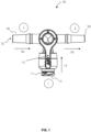
- FIG. 1 illustrates a top view of a multi-port stopcock device-three-port embodiment 100.
- a three-way stopcock device comprising three ports: an inlet port (A), an outlet port (B), and a calibration port (C), according to an embodiment of the invention.
- An inlet portion (A) further comprising patient fluid entry 102, which flows in from the male barbed slip tip 108 in the direction of patient fluid flow in 106.
- the default mode for the patient fluid flow out occurs at the outlet port (B), further comprising patient fluid flow out 104, where the outlet port (B) typically flows back to the patient through the male barbed slip tip 108.
- a second mode for fluid flow occurs at the calibration port (C), further comprising the female self sealing luer tip 112/ swabable tip 114, where a calibration/cleaning fluid flow in 116 flows from port (C) to an outlet port.
- a mechanism comprising a portion, lever 110, controls the flow of the patient fluid and calibration/cleaning fluid. As shown in FIG. 1 , the lever portion is "off' to the calibration/cleaning fluid, allowing only the patient fluid flow in 106 to flow through to the patient fluid flow out 104.
- Opening the lever 110 to port (C) allows the calibration/cleaning fluid flow in 116 to flow from port (C) through the female self sealing luer tip 112/ swabable tip 114, through to the patient fluid flow out 104 (in a three-port embodiment), or to an additional waste port (which can be seen in FIG. 6- FIG. 7 .
- the lever 110 may be pivoted between positions manually or remotely via an electronic mechanism.
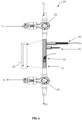
- FIG. 2 illustrates a side view of the multi-port stopcock device- three-port embodiments 200 device, viewed along the axis of the outlet port (B).
- the lever 110 is open to port (C), further comprising a female self sealing luer tip 112/ swabable tip 114, allowing the calibration/cleaning fluid flow in 116 from port (C).
- FIG. 3 illustrates a cross-sectional view of the multi-port stopcock device- three-port embodiment 300 illustrating the mechanism for flow control of the lever 110, namely a rotatable t-channel 302, which blocks or allows fluid to flow.
- the rotatable t-channel 302 is open to port (A), allowing patient fluid entry 102 to flow from patient fluid flow in 106 to Port (B), and out through patient fluid flow out 104.
- the rotatable t-channel 302 is closed to port (C), blocking calibration/cleaning fluid flow in 116 from entering.
- FIG. 4 illustrates a rear view of a three-port stopcock device, viewed along the axis of the calibration port (C).
- the inlet and outlet ports of Ports A and B respectively connect to fluid sources or reservoirs via male barbed slip tips 108.
- Calibration or cleaning fluid may flow in through a syringe, connectable to Port C of the stopcock device via the female self sealing luer tip 112.
- Port C may alternatively comprise a swabable tip 114, or a combination of luer and swabable tips 112, 114.
- FIG. 5 illustrates a multi-port stopcock flow cell device 500, embodiment comprising an inlet port (A), an outlet port (B), a calibration/cleaning port (C), a calibration/cleaning outlet port (D), connected by means of a Flow cell 510, which comprises multiple biosensors 504, 506, 508, the biosensors capable of measuring fluid properties.
- the multiport stopcock device preferably comprises: one or more inlet ports(A,C), receiving fluid from a fluid source, fluidically connected by a flow cell 510 comprising one or more fluid channels(shown in FIG. 6-7 ), to one or more outlet ports(B,D); and a mechanism (i.e. the lever 110) for diverting flow of fluid between ports and fluid channels, wherein: at least one of the one or more inlet ports comprises an inlet tip, connectable to a syringe, and a slip tip, connectable to said fluid source, and at least one of the one or more outlet ports comprises an inlet tip, connectable to a syringe, and a slip tip, connectable to a reservoir.
- flow of the patient fluid flow in 106 and calibration/cleaning fluid flow in 116 enter from ports (A) and (C), respectively, by means of a lever 110, located at the junction between ports (A) and (C) as in the previously described embodiment.
- the patient fluid flow out 104and calibration/cleaning fluid flow out 502 are controlled by an additional lever 110 located at the junction between ports (B) and (D).
- the biosensors Upon fluid flowing through the flow cell 510, and over the biosensors 504, 506, 508, the biosensors measure data relating to fluid properties, and send the measured data, via a connection mechanism 512, to a computing device 524.
- the connection mechanism 512 may be wired or wireless, and may include, but is not limited to, the internet, a wired connection, Bluetooth, NFC, and any other connection mechanisms known in the art.
- the data may be sent to cloud storage, and downloadable to the computing device 524.
- the computing device 524 may comprise a computer, laptop, smart phone, tablet, or any other computing device known in the art.
- the computing device 524 may be on-site, with the multi-port stopcock flow cell device 500, or remote from it. In an example, data may be measured at a patient's home, and automatically sent, via the internet, to a hospital or lab environment for analysis.
- FIG. 6 illustrates a multi-port stopcock flow cell device- four port, one channel embodiment 600 comprising an inlet port (A), an outlet port (B), a calibration/cleaning port (C), a calibration/cleaning outlet port (D), with stopcocks 604 and 606 located at the inlet ports and the outlet ports, connected by means of a Flow cell 510, which comprises multiple biosensors 504, 506, 508, wherein the flow of either the patient fluid flow in 106 or the calibration/cleaning fluid flow in 116 is directed along Path 1 - over Path 1- over the Path 1 - over biosensors 602.
- Internal view- fluid channel 608 illustrates one fluid channel, comprising a path 1 - over biosensors 602, for fluids to flow through.
- Fluids pass through the entry stopcock 604 from patient fluid entry 102 or from calibration/cleaning fluid flow in 116, according to whether stopcock device is in calibration mode or non-calibration mode.
- FIG. 7 illustrates a multi-port stopcock flow cell device- four port, two channel embodiment 700, comprising an inlet port (A), an outlet port (B), a calibration/cleaning port (C), a calibration/cleaning outlet port (D), with stopcocks 604 and 606 located at the inlet ports and the outlet ports, connected by means of a Flow cell 510, which comprises multiple biosensors 504, 506, 508, wherein the flow of either the patient fluid flow in 106 or the calibration/cleaning fluid flow in 116 is directed along either or both of two channels- Path 1-over the biosensors 710, and Path 2- bypass 712.
- Fluids pass through the entry stopcock 604 from patient fluid entry 102 or from calibration/cleaning fluid flow in 116, and are either passed through the Flow cell 510, over the biosensors, to the patient fluid flow out 104 or through the Flow cell 510, to Path 1 - over biosensors 602,to the calibration/cleaning fluid flow out 502.
- the flow cell may be equipped with a bubble removal means 714.
- the computing device 524 may be communicatively coupled with an active bubble removal means 714, including, but not limited to, a vibration motor, ultrasonicating device, or the like, where the active bubble removal means may be within the stopcock or the flow cell (or both), and may be automatically activated by the method, such that the vibration of the motor breaks up the bubbles.
- active bubble removal means 714 including, but not limited to, a vibration motor, ultrasonicating device, or the like, where the active bubble removal means may be within the stopcock or the flow cell (or both), and may be automatically activated by the method, such that the vibration of the motor breaks up the bubbles.
- Other active techniques, communicatively to the computing device may include optical, electric, mechanical, or thermal fields, or combinations thereof. This embodiment is discussed in greater detail with respect to FIG. 8A .
- a passive bubble removal means 714 including, but not limited to, bubble traps on or in the flow cell, or at inlet ports of the flow cell. Bubble traps may be used in combination with vacuum pumps if a sample needs to be degassed. Bubble traps may be commercially available or may be formed by adjusting the geometry of the inlet ports or flow cells.
- the signals measured by the sensors are sent to a computing device (via, for example, the internet, a wired connection, bluetooth, NFC, and any other connection mechanisms known in the art).
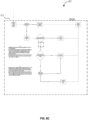
- FIGS 8 . A-C comprise flow charts relating to Data validation 800, and applications of the methods.
- FIGS, 8 A-C relate to EC and pH sensor calibration methods. It should be readily understood that this method may be applied to calibration of other sensors that require external calibrators, such as UV-VIS, optical sensors, lactate, glucose, and the like.
- Instructions for performing the method may be stored on a computer readable, non-transitory medium, that, when executed by a computer, cause it to perform the steps described below.
- the steps may be described as two alternating steps, and a third step.
- Alternating data validation ( FIG. 8A ) and data calibration ( FIG. 8B ) steps are performed each pair of validation and calibration steps corresponding to a calibration fluid flowing through the flow cell and being measured by the sensors 504- 508, in the flow cell 510.
- the calibration data is then filtered/ augmented in a third, filtering/augmentation step ( FIG. 8C ).
- the third step may be performed after all of the data validation and calibration steps.
- FIG. A-C relate to methods of in-situ calibration.
- the method for in-situ calibration of a multi-port stopcock flow cell generally comprises executing, by a computing device, instructions stored on the memory, which cause the processor to perform the steps:
- the method involves the following:
- FIG. 8A Data validation 800
- FIG. 8B data calibration 801
- FIG. 8C calibration artifact filtration 802
- the method may further employ various decision making engines which evaluate the calibration data in order to decide which data may be best suited for determining calibration artifacts. For example, very high or very low pH or conductivity may be filtered out of the calibration, and data determined to be invalid due to the presence of bubbles may be filtered out.
- Calibrated data from the method disclosed above is preferably used to process fluid data, i.e. from a patient.
- the multiport stopcock device may be in fluid communication with a patient, such as by connection to a patient catheter, for monitoring patient biofluids.
- Using the multi-port stopcock flow cell device allows for multiple sensor calibrations and readings, without disconnecting the device from the patient.
- the device may alternatively be calibrated elsewhere, and measurements may be performed at the point of care, i.e. at the patient's home. Additional sensor readings may relate to pH, lactate, amylase, urea, creatinine, electrical conductivity, light absorbance, and/or colour.
- Machine learning algorithms may be applied to previously acquired signal data associated with a user condition or calibration anomalies. For example, pattern recognition may be performed on previously acquired signal data that is associated with a particular user condition. The machine leaning may generate a user condition classification model trained by the previously acquired signal data.
- Deep Belief Network DNN
- SBE Deep Belief Network
- CNN Convolutional Neural Network
- RNN Recurrent Neural Network
- Other examples include, without limitation, Restricted Boltzmann machines (RBM), Social Restricted Boltzmann Machines (SRBM), Fuzzy Restricted Boltzmann Machines (FRBM), TTRBM models of Deep Belief Networks (DBN) or similar approaches could be used; AE, FAE, GAE, DAE, BAE models of Statistically Adjusted End Use (SAE) models could be used; models such as AlexNet, ResNet, Inception, VGG16, ECNN models of CNN may be used; Bidirectional Recurrent Neural Networks (BiRNN), Long Short-Term Memory (LSTM) networks, Gate Recurrent Unit (GRU) of RNN may also be used. Additional techniques specific to time-series modelling may be employed, including, but not limited to, dynamic time warping, change point detection,
- CA cumulative average
- the present disclosure includes systems having processors to provide various functionality to process information, and to determine results based on inputs.
- the processing may be achieved with a combination of hardware and software elements.
- the hardware aspects may include combinations of operatively coupled hardware components including microprocessors, logical circuitry, communication/networking ports, digital filters, memory, or logical circuitry.
- the processors may be adapted to perform operations specified by a computer-executable code, which may be stored on a non-transitory computer readable medium.
- processors and/or machines employed by embodiments of the present disclosure for any processing or evaluation may include one or more networked or non-networked general purpose computer systems, microprocessors, field programmable gate arrays (FPGA's), digital signal processors (DSP's), micro-controllers, and the like, programmed according to the teachings of the exemplary embodiments discussed above and appreciated by those skilled in the computer and software arts.
- the exemplary embodiments of the present invention may include software for controlling the devices and subsystems of the exemplary embodiments, for processing data and signals, for enabling the devices and subsystems of the exemplary embodiments to interact with a human user or the like.
- software can include, but is not limited to, device drivers, firmware, operating systems, development tools, applications software, and the like.
- Such computer-readable media further can include the computer program product of an embodiment of the present invention for preforming all or a portion (if processing is distributed) of the processing performed in implementations.
- Computer code devices of the exemplary embodiments of the present invention can include any suitable interpretable or executable code mechanism, including but not limited to scripts, interpretable programs, dynamic link libraries (DLLs), complete executable programs and the like.
- Computer-readable media may include, for example, magnetic disks, flash memory, RAM, a PROM, an EPROM, a FLASH-EPROM, or any other suitable memory chip or medium from which a computer or processor can read.
Landscapes
- Health & Medical Sciences (AREA)
- Life Sciences & Earth Sciences (AREA)
- Heart & Thoracic Surgery (AREA)
- Animal Behavior & Ethology (AREA)
- Veterinary Medicine (AREA)
- Engineering & Computer Science (AREA)
- Biomedical Technology (AREA)
- Public Health (AREA)
- General Health & Medical Sciences (AREA)
- Physics & Mathematics (AREA)
- Hematology (AREA)
- Pathology (AREA)
- Surgery (AREA)
- Molecular Biology (AREA)
- Medical Informatics (AREA)
- Biophysics (AREA)
- Pulmonology (AREA)
- Anesthesiology (AREA)
- Optics & Photonics (AREA)
- Infusion, Injection, And Reservoir Apparatuses (AREA)
Applications Claiming Priority (1)
| Application Number | Priority Date | Filing Date | Title |
|---|---|---|---|
| US202263373623P | 2022-08-26 | 2022-08-26 |
Publications (2)
| Publication Number | Publication Date |
|---|---|
| EP4338785A2 true EP4338785A2 (de) | 2024-03-20 |
| EP4338785A3 EP4338785A3 (de) | 2024-05-22 |
Family
ID=87845606
Family Applications (1)
| Application Number | Title | Priority Date | Filing Date |
|---|---|---|---|
| EP23193420.9A Pending EP4338785A3 (de) | 2022-08-26 | 2023-08-25 | Vorrichtung, system und verfahren zur in-situ-kalibrierung von biosensoren |
Country Status (3)
| Country | Link |
|---|---|
| US (1) | US20240065587A1 (de) |
| EP (1) | EP4338785A3 (de) |
| CA (1) | CA3210197A1 (de) |
Families Citing this family (1)
| Publication number | Priority date | Publication date | Assignee | Title |
|---|---|---|---|---|
| WO2025199653A1 (en) * | 2024-03-28 | 2025-10-02 | Nerv Technology Inc. | Systems and methods for one-point, on-site calibration of sensors |
Citations (4)
| Publication number | Priority date | Publication date | Assignee | Title |
|---|---|---|---|---|
| DE19715441C1 (de) | 1997-04-10 | 1998-09-17 | Inst Bioprozess Analysenmesst | Verfahren zur In-situ-Kalibrierung von in die Probenlösung eintauchenden Chemo- oder Biosensoren |
| US7695445B2 (en) | 2001-11-14 | 2010-04-13 | Jms Co., Ltd. | Three-way stopcock, and liquid transfusion circuit or blood transfusion circuit either using the three-way stopcock |
| US9089292B2 (en) | 2010-03-26 | 2015-07-28 | Medtronic Minimed, Inc. | Calibration of glucose monitoring sensor and/or insulin delivery system |
| US10561832B2 (en) | 2015-04-15 | 2020-02-18 | Guerbet | Medical stopcock, kit comprising such a stopcock, and method for preparing a mixture or an emulsion |
Family Cites Families (5)
| Publication number | Priority date | Publication date | Assignee | Title |
|---|---|---|---|---|
| US6158467A (en) * | 1998-01-08 | 2000-12-12 | George Loo | Four-port, four-way, stopcock for intravenous injections and infusions and direction of flow of fluids and gasses |
| US9050401B2 (en) * | 2010-05-19 | 2015-06-09 | Angioadvancements, Llc | System for controlled delivery of medical fluids |
| US9357950B2 (en) * | 2009-06-03 | 2016-06-07 | Biometrix Ltd. | Apparatus and method of fluid aspiration |
| US9649436B2 (en) * | 2011-09-21 | 2017-05-16 | Bayer Healthcare Llc | Assembly method for a fluid pump device for a continuous multi-fluid delivery system |
| US10549248B2 (en) * | 2015-04-23 | 2020-02-04 | B. Braun Medical Inc. | Compounding device system, software and method for controlling the process of compounding admixtures |
-
2023
- 2023-08-25 US US18/456,096 patent/US20240065587A1/en active Pending
- 2023-08-25 CA CA3210197A patent/CA3210197A1/en active Pending
- 2023-08-25 EP EP23193420.9A patent/EP4338785A3/de active Pending
Patent Citations (4)
| Publication number | Priority date | Publication date | Assignee | Title |
|---|---|---|---|---|
| DE19715441C1 (de) | 1997-04-10 | 1998-09-17 | Inst Bioprozess Analysenmesst | Verfahren zur In-situ-Kalibrierung von in die Probenlösung eintauchenden Chemo- oder Biosensoren |
| US7695445B2 (en) | 2001-11-14 | 2010-04-13 | Jms Co., Ltd. | Three-way stopcock, and liquid transfusion circuit or blood transfusion circuit either using the three-way stopcock |
| US9089292B2 (en) | 2010-03-26 | 2015-07-28 | Medtronic Minimed, Inc. | Calibration of glucose monitoring sensor and/or insulin delivery system |
| US10561832B2 (en) | 2015-04-15 | 2020-02-18 | Guerbet | Medical stopcock, kit comprising such a stopcock, and method for preparing a mixture or an emulsion |
Also Published As
| Publication number | Publication date |
|---|---|
| CA3210197A1 (en) | 2024-02-26 |
| EP4338785A3 (de) | 2024-05-22 |
| US20240065587A1 (en) | 2024-02-29 |
Similar Documents
| Publication | Publication Date | Title |
|---|---|---|
| EP3723608B1 (de) | Sensorüberwachungssystem für verweilkatheterbasierte behandlungen | |
| JP3542595B2 (ja) | 液体サンプリングモジュール | |
| US20170281064A1 (en) | System and method for early detection of post-surgery infection | |
| US20240006075A1 (en) | Systems and methods for predicting and detecting post-operative complications | |
| EP3967346A1 (de) | Verfahren, schaltungen, vorrichtungen, anordnungen, systeme und zugehöriger computerausführbarer code zum erfassen und analysieren von fluideigenschaften innerhalb einer leitung einer medizinischen vorrichtung und luftblasen darin | |
| CN107727532B (zh) | 腹膜透析液流径感测 | |
| CN106030303B (zh) | 自校准血室 | |
| EP4338785A2 (de) | Vorrichtung, system und verfahren zur in-situ-kalibrierung von biosensoren | |
| WO2019178159A1 (en) | Fluid analyte detection systems and methods | |
| US20230149608A1 (en) | Fluid sensor system | |
| JP2008518205A (ja) | インターフェレントを有するサンプル内の被検体濃度を決定する方法と装置 | |
| US20100094114A1 (en) | Use of multiple calibration solutions with an analyte sensor with use in an automated blood access system | |
| US20110060199A1 (en) | Determination of blood pump system performance and sample dilution using a property of fluid being transported | |
| US20240035948A1 (en) | A cell counter and diagnostic device | |
| WO2009117416A1 (en) | Biological sample quality determination | |
| US20240260902A1 (en) | Modular sensor platform for inline biomarker monitoring | |
| EP2538844A1 (de) | Vorrichtung, system und verfahren für den nachweis von analytkonzentrationen in einem durchfluss | |
| US20250302347A1 (en) | Systems and methods for one-point, on-site calibration of sensors | |
| CN120152684A (zh) | 流体收集装置 | |
| CA3143250C (en) | System and method of measurement and calibration of analyte testing | |
| CN117968791B (zh) | 一种快速实现多通道体积计量的装置 | |
| WO2026044426A1 (en) | Systems and methods for continuously monitoring blood analytes | |
| WO2025252891A1 (en) | Fluid monitoring system and method | |
| BR102018073629A2 (pt) | Dispositivo e processo para análise da turbidez do líquido peritoneal dialisado | |
| HK40083555B (en) | A cell counter and diagnostic device |
Legal Events
| Date | Code | Title | Description |
|---|---|---|---|
| PUAI | Public reference made under article 153(3) epc to a published international application that has entered the european phase |
Free format text: ORIGINAL CODE: 0009012 |
|
| STAA | Information on the status of an ep patent application or granted ep patent |
Free format text: STATUS: THE APPLICATION HAS BEEN PUBLISHED |
|
| AK | Designated contracting states |
Kind code of ref document: A2 Designated state(s): AL AT BE BG CH CY CZ DE DK EE ES FI FR GB GR HR HU IE IS IT LI LT LU LV MC ME MK MT NL NO PL PT RO RS SE SI SK SM TR |
|
| PUAL | Search report despatched |
Free format text: ORIGINAL CODE: 0009013 |
|
| AK | Designated contracting states |
Kind code of ref document: A3 Designated state(s): AL AT BE BG CH CY CZ DE DK EE ES FI FR GB GR HR HU IE IS IT LI LT LU LV MC ME MK MT NL NO PL PT RO RS SE SI SK SM TR |
|
| RIC1 | Information provided on ipc code assigned before grant |
Ipc: A61M 39/22 20060101AFI20240417BHEP |
|
| STAA | Information on the status of an ep patent application or granted ep patent |
Free format text: STATUS: REQUEST FOR EXAMINATION WAS MADE |
|
| 17P | Request for examination filed |
Effective date: 20241108 |
|
| RBV | Designated contracting states (corrected) |
Designated state(s): AL AT BE BG CH CY CZ DE DK EE ES FI FR GB GR HR HU IE IS IT LI LT LU LV MC ME MK MT NL NO PL PT RO RS SE SI SK SM TR |
|
| STAA | Information on the status of an ep patent application or granted ep patent |
Free format text: STATUS: EXAMINATION IS IN PROGRESS |
|
| 17Q | First examination report despatched |
Effective date: 20250401 |