EP4338820A1 - Procédé de purification de gaz électroniques et dispositif de purification pour le procédé - Google Patents
Procédé de purification de gaz électroniques et dispositif de purification pour le procédé Download PDFInfo
- Publication number
- EP4338820A1 EP4338820A1 EP22195697.2A EP22195697A EP4338820A1 EP 4338820 A1 EP4338820 A1 EP 4338820A1 EP 22195697 A EP22195697 A EP 22195697A EP 4338820 A1 EP4338820 A1 EP 4338820A1
- Authority
- EP
- European Patent Office
- Prior art keywords
- gas
- purification
- purification device
- electronic
- gases
- Prior art date
- Legal status (The legal status is an assumption and is not a legal conclusion. Google has not performed a legal analysis and makes no representation as to the accuracy of the status listed.)
- Withdrawn
Links
- 239000007789 gas Substances 0.000 title claims abstract description 328
- 238000000746 purification Methods 0.000 title claims abstract description 236
- 238000000034 method Methods 0.000 title claims abstract description 89
- 230000008569 process Effects 0.000 claims abstract description 38
- 239000012510 hollow fiber Substances 0.000 claims abstract description 23
- 229910052751 metal Inorganic materials 0.000 claims description 49
- 239000002184 metal Substances 0.000 claims description 49
- 239000012535 impurity Substances 0.000 claims description 30
- VNWKTOKETHGBQD-UHFFFAOYSA-N methane Chemical compound C VNWKTOKETHGBQD-UHFFFAOYSA-N 0.000 claims description 28
- 239000001257 hydrogen Substances 0.000 claims description 27
- 229910052739 hydrogen Inorganic materials 0.000 claims description 27
- CURLTUGMZLYLDI-UHFFFAOYSA-N Carbon dioxide Chemical compound O=C=O CURLTUGMZLYLDI-UHFFFAOYSA-N 0.000 claims description 24
- XKRFYHLGVUSROY-UHFFFAOYSA-N Argon Chemical compound [Ar] XKRFYHLGVUSROY-UHFFFAOYSA-N 0.000 claims description 22
- 150000002431 hydrogen Chemical class 0.000 claims description 22
- QVGXLLKOCUKJST-UHFFFAOYSA-N atomic oxygen Chemical compound [O] QVGXLLKOCUKJST-UHFFFAOYSA-N 0.000 claims description 20
- 239000001301 oxygen Substances 0.000 claims description 20
- 229910052760 oxygen Inorganic materials 0.000 claims description 20
- MWUXSHHQAYIFBG-UHFFFAOYSA-N Nitric oxide Chemical compound O=[N] MWUXSHHQAYIFBG-UHFFFAOYSA-N 0.000 claims description 18
- 229910002092 carbon dioxide Inorganic materials 0.000 claims description 17
- 239000001569 carbon dioxide Substances 0.000 claims description 17
- 239000000463 material Substances 0.000 claims description 16
- IJGRMHOSHXDMSA-UHFFFAOYSA-N Atomic nitrogen Chemical compound N#N IJGRMHOSHXDMSA-UHFFFAOYSA-N 0.000 claims description 14
- UGFAIRIUMAVXCW-UHFFFAOYSA-N Carbon monoxide Chemical compound [O+]#[C-] UGFAIRIUMAVXCW-UHFFFAOYSA-N 0.000 claims description 13
- 229910002091 carbon monoxide Inorganic materials 0.000 claims description 13
- 229910052786 argon Inorganic materials 0.000 claims description 11
- XLYOFNOQVPJJNP-UHFFFAOYSA-N water Substances O XLYOFNOQVPJJNP-UHFFFAOYSA-N 0.000 claims description 8
- -1 methane hydrocarbon Chemical class 0.000 claims description 7
- ARXJGSRGQADJSQ-UHFFFAOYSA-N 1-methoxypropan-2-ol Chemical compound COCC(C)O ARXJGSRGQADJSQ-UHFFFAOYSA-N 0.000 claims description 6
- HZAXFHJVJLSVMW-UHFFFAOYSA-N 2-Aminoethan-1-ol Chemical compound NCCO HZAXFHJVJLSVMW-UHFFFAOYSA-N 0.000 claims description 6
- 239000004215 Carbon black (E152) Substances 0.000 claims description 6
- 229930195733 hydrocarbon Natural products 0.000 claims description 6
- UFHFLCQGNIYNRP-UHFFFAOYSA-N Hydrogen Chemical compound [H][H] UFHFLCQGNIYNRP-UHFFFAOYSA-N 0.000 claims description 5
- 150000001875 compounds Chemical class 0.000 claims description 4
- 239000000126 substance Substances 0.000 claims description 4
- OKTJSMMVPCPJKN-UHFFFAOYSA-N Carbon Chemical compound [C] OKTJSMMVPCPJKN-UHFFFAOYSA-N 0.000 claims description 3
- 239000002253 acid Substances 0.000 claims description 3
- 150000007513 acids Chemical class 0.000 claims description 3
- 229910052799 carbon Inorganic materials 0.000 claims description 3
- 238000007599 discharging Methods 0.000 claims description 3
- 238000010926 purge Methods 0.000 claims description 3
- 239000003054 catalyst Substances 0.000 description 7
- 230000000694 effects Effects 0.000 description 7
- 238000002347 injection Methods 0.000 description 7
- 239000007924 injection Substances 0.000 description 7
- 239000001307 helium Substances 0.000 description 4
- 229910052734 helium Inorganic materials 0.000 description 4
- SWQJXJOGLNCZEY-UHFFFAOYSA-N helium atom Chemical compound [He] SWQJXJOGLNCZEY-UHFFFAOYSA-N 0.000 description 4
- 238000004519 manufacturing process Methods 0.000 description 4
- 229910052757 nitrogen Inorganic materials 0.000 description 4
- 230000001105 regulatory effect Effects 0.000 description 4
- 230000009467 reduction Effects 0.000 description 3
- 238000001179 sorption measurement Methods 0.000 description 3
- QJGQUHMNIGDVPM-UHFFFAOYSA-N nitrogen group Chemical group [N] QJGQUHMNIGDVPM-UHFFFAOYSA-N 0.000 description 2
- 239000002245 particle Substances 0.000 description 2
- 238000005476 soldering Methods 0.000 description 2
- 239000000853 adhesive Substances 0.000 description 1
- 230000001070 adhesive effect Effects 0.000 description 1
- 230000015572 biosynthetic process Effects 0.000 description 1
- 230000008859 change Effects 0.000 description 1
- 238000009792 diffusion process Methods 0.000 description 1
- 230000009977 dual effect Effects 0.000 description 1
- 238000005265 energy consumption Methods 0.000 description 1
- 238000005530 etching Methods 0.000 description 1
- 239000010408 film Substances 0.000 description 1
- 238000001914 filtration Methods 0.000 description 1
- UQEAIHBTYFGYIE-UHFFFAOYSA-N hexamethyldisiloxane Chemical compound C[Si](C)(C)O[Si](C)(C)C UQEAIHBTYFGYIE-UHFFFAOYSA-N 0.000 description 1
- 230000004941 influx Effects 0.000 description 1
- 230000010354 integration Effects 0.000 description 1
- 230000004048 modification Effects 0.000 description 1
- 238000012986 modification Methods 0.000 description 1
- 229940110728 nitrogen / oxygen Drugs 0.000 description 1
- 239000013307 optical fiber Substances 0.000 description 1
- 239000011148 porous material Substances 0.000 description 1
- 230000001681 protective effect Effects 0.000 description 1
- 239000004065 semiconductor Substances 0.000 description 1
- 239000000243 solution Substances 0.000 description 1
- 238000003786 synthesis reaction Methods 0.000 description 1
- 239000010409 thin film Substances 0.000 description 1
- 238000007740 vapor deposition Methods 0.000 description 1
- 230000003313 weakening effect Effects 0.000 description 1
Images








Classifications
-
- B—PERFORMING OPERATIONS; TRANSPORTING
- B01—PHYSICAL OR CHEMICAL PROCESSES OR APPARATUS IN GENERAL
- B01D—SEPARATION
- B01D53/00—Separation of gases or vapours; Recovering vapours of volatile solvents from gases; Chemical or biological purification of waste gases, e.g. engine exhaust gases, smoke, fumes, flue gases, aerosols
- B01D53/02—Separation of gases or vapours; Recovering vapours of volatile solvents from gases; Chemical or biological purification of waste gases, e.g. engine exhaust gases, smoke, fumes, flue gases, aerosols by adsorption, e.g. preparative gas chromatography
- B01D53/04—Separation of gases or vapours; Recovering vapours of volatile solvents from gases; Chemical or biological purification of waste gases, e.g. engine exhaust gases, smoke, fumes, flue gases, aerosols by adsorption, e.g. preparative gas chromatography with stationary adsorbents
- B01D53/0407—Constructional details of adsorbing systems
-
- B—PERFORMING OPERATIONS; TRANSPORTING
- B01—PHYSICAL OR CHEMICAL PROCESSES OR APPARATUS IN GENERAL
- B01D—SEPARATION
- B01D53/00—Separation of gases or vapours; Recovering vapours of volatile solvents from gases; Chemical or biological purification of waste gases, e.g. engine exhaust gases, smoke, fumes, flue gases, aerosols
- B01D53/22—Separation of gases or vapours; Recovering vapours of volatile solvents from gases; Chemical or biological purification of waste gases, e.g. engine exhaust gases, smoke, fumes, flue gases, aerosols by diffusion
- B01D2053/221—Devices
- B01D2053/223—Devices with hollow tubes
- B01D2053/224—Devices with hollow tubes with hollow fibres
-
- B—PERFORMING OPERATIONS; TRANSPORTING
- B01—PHYSICAL OR CHEMICAL PROCESSES OR APPARATUS IN GENERAL
- B01D—SEPARATION
- B01D2257/00—Components to be removed
- B01D2257/10—Single element gases other than halogens
- B01D2257/104—Oxygen
-
- B—PERFORMING OPERATIONS; TRANSPORTING
- B01—PHYSICAL OR CHEMICAL PROCESSES OR APPARATUS IN GENERAL
- B01D—SEPARATION
- B01D2257/00—Components to be removed
- B01D2257/10—Single element gases other than halogens
- B01D2257/108—Hydrogen
-
- B—PERFORMING OPERATIONS; TRANSPORTING
- B01—PHYSICAL OR CHEMICAL PROCESSES OR APPARATUS IN GENERAL
- B01D—SEPARATION
- B01D2257/00—Components to be removed
- B01D2257/10—Single element gases other than halogens
- B01D2257/11—Noble gases
-
- B—PERFORMING OPERATIONS; TRANSPORTING
- B01—PHYSICAL OR CHEMICAL PROCESSES OR APPARATUS IN GENERAL
- B01D—SEPARATION
- B01D2257/00—Components to be removed
- B01D2257/40—Nitrogen compounds
- B01D2257/404—Nitrogen oxides other than dinitrogen oxide
-
- B—PERFORMING OPERATIONS; TRANSPORTING
- B01—PHYSICAL OR CHEMICAL PROCESSES OR APPARATUS IN GENERAL
- B01D—SEPARATION
- B01D2257/00—Components to be removed
- B01D2257/50—Carbon oxides
- B01D2257/502—Carbon monoxide
-
- B—PERFORMING OPERATIONS; TRANSPORTING
- B01—PHYSICAL OR CHEMICAL PROCESSES OR APPARATUS IN GENERAL
- B01D—SEPARATION
- B01D2257/00—Components to be removed
- B01D2257/50—Carbon oxides
- B01D2257/504—Carbon dioxide
-
- B—PERFORMING OPERATIONS; TRANSPORTING
- B01—PHYSICAL OR CHEMICAL PROCESSES OR APPARATUS IN GENERAL
- B01D—SEPARATION
- B01D2257/00—Components to be removed
- B01D2257/70—Organic compounds not provided for in groups B01D2257/00 - B01D2257/602
- B01D2257/702—Hydrocarbons
- B01D2257/7022—Aliphatic hydrocarbons
-
- B—PERFORMING OPERATIONS; TRANSPORTING
- B01—PHYSICAL OR CHEMICAL PROCESSES OR APPARATUS IN GENERAL
- B01D—SEPARATION
- B01D2257/00—Components to be removed
- B01D2257/70—Organic compounds not provided for in groups B01D2257/00 - B01D2257/602
- B01D2257/702—Hydrocarbons
- B01D2257/7022—Aliphatic hydrocarbons
- B01D2257/7025—Methane
-
- B—PERFORMING OPERATIONS; TRANSPORTING
- B01—PHYSICAL OR CHEMICAL PROCESSES OR APPARATUS IN GENERAL
- B01D—SEPARATION
- B01D2258/00—Sources of waste gases
- B01D2258/02—Other waste gases
- B01D2258/0216—Other waste gases from CVD treatment or semi-conductor manufacturing
Definitions
- the present application relates to a method for purification of electronic gases and a purification device for the method in which electronic gases are purified through a purification device and the purification device is reclaimed.
- VLSI super-large-scale integration
- flat panel displays compound semiconductor devices
- solar cells solar cells
- optical fibers have been widely applied in manufacturing processes like thin film, etching, doping, vapor deposition and diffusion.
- 50 different electronic gases are being supplied to more than 450 state-of-the-art wafer manufacturing processes in a VLSI factory.
- electronic gases in the present disclosure are purified through hollow fiber tubes in which different gaseous impurities are adsorbed and multiple materials are added for removals of various gaseous impurities during purification without extra facilities.
- a method for purification of electronic gases in the present disclosure comprises steps for renewal process which is supported by purified electronic gases for the purpose of reuse.
- the present application which is characteristic of cost reduction due to significantly less replacement of consumables compared with consumables used in the prior art can be considered as a preferred solution.
- a method for purification of electronic gases comprising:
- the impurities which are removed by the purification device through the plurality of hollow fiber tubes comprise one or more substances from the group of water (H 2 O), oxygen (O 2 ), nitrogen (N 2 ), hydrogen (H 2 ), methane (CH 4 ), carbon monoxide (CO), carbon dioxide (CO 2 ), non-methane hydrocarbon (NMHC), argon (Ar), nitrogen oxide (NOx), total organic carbon (TOC), acids, bases, refactory compounds, propylene glycol monomethyl ether (PGME) and monoethanolamine (MEA).
- the impurities removed by the purification device comprise oxygen (O 2 )
- hydrogen (H 2 ) is injected into the purification device which is not operating gas purification to remove the impurities like residual oxygen (O 2 ) inside the plurality of hollow fiber tubes during the renewal process.
- argon (Ar) is injected into the purification device which is not operating gas purification for purging and removal of residual hydrogen (H 2 ) inside the plurality of hollow fiber tubes in the case of hydrogen leakage when the unpurified electronic gas or the removed impurity is hydrogen (H 2 ).
- the purification device, the gas input unit, the pressure regulator and a filter are connected through different tubes in which each of tubes connected with the purification device for gas purification features a diameter greater than a diameter of each of tubes connected with the purification device for renewal process and a gas flow rate for renewal process is 1-5% of a gas flow rate for gas purification.
- a purification device comprises: a gas cylinder with a front opening and a rear opening; a gas purification assembly positioned inside the gas cylinder and comprising at least a purification material body in which a bunch of hollow fiber tubes are filled; a front cover body covered on the front opening of the gas cylinder and comprising a front gas port thereon as well as a front sintered metal filter with multiple front gas vents at an inner side of the front cover body, wherein a front gas flowing space is formed between the front gas port and the front sintered metal filter, and a front space is formed between the front sintered metal filter and one end of the purification material body; and a rear cover body covered on the rear opening of the gas cylinder and comprising a rear gas port thereon as well as a rear sintered metal filter with multiple rear gas vents at an inner side of the rear cover body, wherein a rear gas flowing space is formed between the rear gas port and the rear sintered metal filter, a rear space is formed between the rear sintered metal filter and the other end of the purification material body
- the front gas vent features a bore diameter ranging from 100 mm to 200 mm and the rear gas ventfeatures a bore diameter ranging from 20 mm to 100mm.
- the gas purification assembly further comprises a front metal sleeve ring, a rear metal sleeve ring and at least a metal clamp, the purification material body is fastened with the front metal sleeve ring at one end and the rear metal sleeve ring at the other end, and each of the front metal sleeve ring and the rear metal sleeve ring is welded and fixed on an inner wall of the gas cylinder.
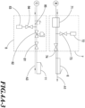
- FIG. 2 which illustrates a flowchart with respect to a method for purification of electronic gases and a purification device for the method wherein the method is shown as follows:
- each of different purification devices is connected with a gas input unit through a purifying gas intake tube wherein the gas input unit is used in driving an unpurified electronic gas into the purification device through a purifying gas intake tube for gas purification and discharging a purified electronic gas outward from the purification device through a purifying gas exhaust tube.
- a purifying gas intake tube and a purifying gas intake control valve are connected with each other in series wherein the purifying gas intake control valve is capable of regulating entry of an unpurified electronic gas into the purification device; a purifying gas exhaust tube and a purifying gas exhaust control valve are connected with each other in series wherein the purifying gas exhaust control valve is capable of regulating discharge of the purified electronic gas outward through the purifying gas exhaust tube.
- step 202 the purifying gas exhaust tube is distributed to and connected with the pressure regulator and each of different purification devices is connected with the pressure regulator through a renewal gas intake tube.
- the pressure regulator receives a purified electronic gas discharged outward through the purifying gas exhaust tube; the purified electronic gas, depressurized and heated, is delivered into a purification device not running for gas purification from the renewal gas intake tube.
- the pressure regulator and a gas intake manifold are connected with each other in series; the gas intake manifold and a gas intake control valve are further connected with each other in series.
- the gas intake control valve located between the purifying gas exhaust control valve and the pressure regulator is used in regulating entry of a purified electronic gas discharged outward from the purifying gas exhaust tube into the pressure regulator.
- each of different purification devices is connected with an exhaust outlet through a renewal gas exhaust tube and the purified electronic gas, depressurized and heated, is discharged through the renewal gas exhaust tube for removals of fine dusts inside a plurality of hollow fiber tubes and completion of renewal process.
- the renewal gas intake tube and a renewal gas intake control valve are connected with each other in series; the renewal gas intake control valve is used in regulating entry of the purified electronic gas, depressurized and heated, into a purification device which is not operating gas purification; the renewal gas exhaust tube and a renewal gas exhaust control valve are connected with each other in series such that the purified electronic gas, depressurized and heated, is discharged through the renewal gas exhaust tube controllably.
- a purified electronic gas (neither depressurized nor heated) is delivered into a purification device in which no gas purification is running through a renewal gas intake tube connected with another purification device in which gas purification is running as well as an opened renewal gas intake control valve linking another renewal gas intake tube such that backpressure inside the purification device is restored and equal to the pressure of gas injected by the gas input unit.
- each tube connected for gas purification is larger than the diameter of each tube connected with a purification device for renewal process.
- a gas flow is depressurized through a pressure regulator before entry into a purification device.
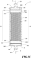
- the purification device 2 comprises a gas cylinder 21, a gas purification assembly 22, a front cover body 23 and a rear cover body 24: the gas cylinder 21 has a front opening 211 and a rear opening 212; the gas purification assembly 22 is positioned inside the gas cylinder 21.
- the gas purification assembly 22 comprises a front metal sleeve ring 221, a rear metal sleeve ring 222, at least a metal clamp 223 and a purification material body 224: the purification material body 224, which comprises a plurality of hollow fiber tubes, is fastened with the front metal sleeve ring 221 at one end and the rear metal sleeve ring 222 at the other end wherein each of the front metal sleeve ring 221 and the rear metal sleeve ring 222 is welded and fixed on an inner wall of the gas cylinder 21 without shaking of the gas purification assembly 22 inside the gas cylinder.
- the purification material body 224 is covered with protective films 2241, 2242 on the top end and the rear end, respectively.
- the gas purification assembly 22 cannot adhere to inside of the gas cylinder 21 with adhesives, which are brittle substances while contacting with hot gases for renewal process that leave an obvious peeling at a junction behind, collapsing the gas purification assembly 22 and weakening the effect of gas purification by the purification device 2 after renewal process .
- the front cover body 23 covered on the front opening 211 has a front gas port 231 on the surface and a front sintered metal filter 232 at the internal side; the front sintered metal filter 232 is designed to form multiple front gas vents 2321 thereon.
- the rear cover body 24 covered on the rear opening 212 has a rear gas port 241 on the surface and a rear sintered metal filter 242 at the internal side; the rear sintered metal filter 242 is designed to form multiple rear gas vents 2421 thereon.
- Each of the front sintered metal filter 232 and the rear sintered metal filter 242 features a thickness ranging from 2.5 to 4.5mm and preferably 3mm.
- Each of the front gas vents 2321 features a bore diameter ranging from 100 to 200mm (100mm, 101mm, 105mm, 110mm, 115mm, 120mm, 125mm, 130mm, 135mm, 140mm, 145mm, 150mm, 155mm, 160mm, 165mm, 170mm, 175mm, 180mm, 185mm, 190mm, 195mm or 200mm); each of the front gas vents 2321 allows gases from the front gas port 231 to be distributed into the gas purification assembly 22 gradually and remained inside the purification device 2 much longer.
- Each of the rear gas vents 2421 features a bore diameter ranging from 20 to 100mm (20mm, 25mm, 30mm, 35mm, 40mm, 45mm, 50mm, 55mm, 60mm, 65mm, 70mm, 75mm, 80mm, 85mm, 90mm, 95mm, 99mm or 100mm).
- a gas flow which is being discharged through the gas purification assembly 22 collides with the rear sintered metal filter 242 first and bounces back from the rear sintered metal filter 242 (under the backpressure effect) because the diameter of each rear gas vent 2421 in design is less than that of each front gas vent 2321.
- the front gas port 231 and the front sintered metal filter 232 form a front gas flowing space 233 in between.
- Unpurified gases which are diffusing and contacting with all front gas vents 2321 under the function of the front gas flowing space 233 are delivered into the gas purification assembly 2 through multiple front gas vents 2321.
- the effect for influx of unpurified gases diffusing gradually is subject to the undersized front gas flowing space 233 that cuts back on the duration of unpurified gases staying inside the purification device 2. Accordingly, the front sintered metal filter 232 should stay away from the front gas vents 2321.
- the rear gas port 241 and the rear sintered metal filter 242 form a rear gas flowing space 243 in between.
- the rear gas flowing space 243 keeps the rear sintered metal filter 242 away from the rear gas port 241 such that purified gases contact with all rear gas vents 2421 first and access rear gas port 241 by diffusing from the multiple rear gas vents 2421.
- Both the front cover body 23 and the rear cover body 24 are welded and fixed on the front opening 211 and rear opening 212, respectively. Because of high soldering temperature, one position at which the front cover body 23 (the rear cover body 24) is weld on the front opening 211 (the rear opening 212) should be separated from the other position of the front metal sleeve ring 221 (the rear metal sleeve ring 222) vertically (that is, two positions are separated by a front space 213 (a rear space 214)) such that the purification material body 224 of the gas purification assembly 22 does not melt down at high soldering temperature.
- impurities are adsorbed and removed through a plurality of hollow fiber tubes of the purification material body 224 in which capillary pores exist wherein impurities can be one or more substances among water (H 2 O), oxygen (O 2 ), nitrogen (N 2 ), hydrogen (H 2 ), methane (CH 4 ), carbon monoxide (CO), carbon dioxide (CO 2 ), non-methane hydrocarbon (NMHC) , argon (Ar), nitrogen oxide (NOx), total organic carbon (TOC), acids (for example, SO 2 ), bases (for example, NH 3 ), refactory compounds (for example, HMDSO), propylene glycol monomethyl ether (PGME) and monoethanolamine (MEA).
- the purified electronic gas 6 in which no impurity exists is discharged from the rear gas port 241.
- a renewal gas 11 for example, argon (Ar)
- injected through the renewal gas injection unit 8 passes through the renewal gas intake control valve 57B, the purification device 52, the renewal gas exhaust control valve 58B and the filter 9 to dissipate residual hydrogen (H 2 ) inside tubes of a purification device from an exhaust outlet 10.
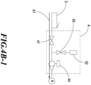
- the gas input unit 4 comprises a component 41, a component 42, a component 43 and a component 44 wherein the component 41, the component 42, the component 43 and the component 44 are a control valve, a pressure transducer, a manual valve/an electrically operated valve and a gas flow meter, respectively.
- the gas output unit 7 comprises a component 71, a component 72, a component 73 and a component 74 wherein the component 71, the component 72, the component 73 and the component 74 are a particle filter, a pressure transducer, a control valve and a manual valve/an electrically operated valve, respectively.
- the renewal gas injection unit 8 comprises a component 81, a component 82, a component 83, a component 84 and a component 85 wherein the component 81, the component 82, the component 83, the component 84 and the component 85 are a control valve, a pressure regulator, a pressure transducer, a control valve and a check valve, respectively.
Landscapes
- Chemical & Material Sciences (AREA)
- Engineering & Computer Science (AREA)
- Analytical Chemistry (AREA)
- General Chemical & Material Sciences (AREA)
- Oil, Petroleum & Natural Gas (AREA)
- Chemical Kinetics & Catalysis (AREA)
- Separation Using Semi-Permeable Membranes (AREA)
Priority Applications (1)
| Application Number | Priority Date | Filing Date | Title |
|---|---|---|---|
| EP22195697.2A EP4338820A1 (fr) | 2022-09-14 | 2022-09-14 | Procédé de purification de gaz électroniques et dispositif de purification pour le procédé |
Applications Claiming Priority (1)
| Application Number | Priority Date | Filing Date | Title |
|---|---|---|---|
| EP22195697.2A EP4338820A1 (fr) | 2022-09-14 | 2022-09-14 | Procédé de purification de gaz électroniques et dispositif de purification pour le procédé |
Publications (1)
| Publication Number | Publication Date |
|---|---|
| EP4338820A1 true EP4338820A1 (fr) | 2024-03-20 |
Family
ID=83319096
Family Applications (1)
| Application Number | Title | Priority Date | Filing Date |
|---|---|---|---|
| EP22195697.2A Withdrawn EP4338820A1 (fr) | 2022-09-14 | 2022-09-14 | Procédé de purification de gaz électroniques et dispositif de purification pour le procédé |
Country Status (1)
| Country | Link |
|---|---|
| EP (1) | EP4338820A1 (fr) |
Citations (6)
| Publication number | Priority date | Publication date | Assignee | Title |
|---|---|---|---|---|
| US20100107879A1 (en) * | 2004-09-27 | 2010-05-06 | Deubler Alfred | Dryer Unit For Compressed Air And Other Gaseous Media |
| US20160166978A1 (en) * | 2014-12-15 | 2016-06-16 | Industrial Technology Research Institute | Co2 adsorption and recovery system and method |
| US20160175765A1 (en) * | 2014-12-18 | 2016-06-23 | Industrial Technology Research Institute | Hollow fiber adsorbent compressed dry air system |
| US20190039914A1 (en) * | 2016-04-22 | 2019-02-07 | Pall Corporation | Water processing device |
| CN111921332A (zh) * | 2019-05-13 | 2020-11-13 | 纯萃材料股份有限公司 | 吸附装置及吸附方法 |
| KR20220046034A (ko) * | 2020-10-06 | 2022-04-14 | 삼성전자주식회사 | 미세다공성 폴리머 섬유 흡착제, 미세다공성 폴리머 섬유 흡착제를 포함한 흡착 모듈, 미세다공성 폴리머 섬유 흡착제를 포함한 흡착 모듈을 이용한 유기 오염 물질 제거 시스템 |
-
2022
- 2022-09-14 EP EP22195697.2A patent/EP4338820A1/fr not_active Withdrawn
Patent Citations (6)
| Publication number | Priority date | Publication date | Assignee | Title |
|---|---|---|---|---|
| US20100107879A1 (en) * | 2004-09-27 | 2010-05-06 | Deubler Alfred | Dryer Unit For Compressed Air And Other Gaseous Media |
| US20160166978A1 (en) * | 2014-12-15 | 2016-06-16 | Industrial Technology Research Institute | Co2 adsorption and recovery system and method |
| US20160175765A1 (en) * | 2014-12-18 | 2016-06-23 | Industrial Technology Research Institute | Hollow fiber adsorbent compressed dry air system |
| US20190039914A1 (en) * | 2016-04-22 | 2019-02-07 | Pall Corporation | Water processing device |
| CN111921332A (zh) * | 2019-05-13 | 2020-11-13 | 纯萃材料股份有限公司 | 吸附装置及吸附方法 |
| KR20220046034A (ko) * | 2020-10-06 | 2022-04-14 | 삼성전자주식회사 | 미세다공성 폴리머 섬유 흡착제, 미세다공성 폴리머 섬유 흡착제를 포함한 흡착 모듈, 미세다공성 폴리머 섬유 흡착제를 포함한 흡착 모듈을 이용한 유기 오염 물질 제거 시스템 |
Similar Documents
| Publication | Publication Date | Title |
|---|---|---|
| KR101164679B1 (ko) | 고순도 유체를 공급하기 위한 방법 및 시스템 | |
| JP4939563B2 (ja) | 半導体装置の製造方法 | |
| US7487806B2 (en) | Source liquid supply apparatus having a cleaning function | |
| CN1367523A (zh) | 一种半导体生产系统 | |
| EP0288931A2 (fr) | Bloque de soupapes et récipient pour sortie et/ou purification de dopage de cathode pour semi-conducteurs | |
| WO2002058858A1 (fr) | Nettoyage non plasma $m(f)i$m(g)in situ$m(f)/i$m(g) de chambres de traitement par des procedes d'ecoulement statique | |
| KR20010076187A (ko) | 삼염화붕소의 정제 방법 및 시스템 | |
| JPH09103633A (ja) | パーフルオロ化合物ガスの分離および回収方法および装置 | |
| JP4271894B2 (ja) | ガス精製装置並びにそれを含む弁アセンブリ及び液化ガス容器系 | |
| US6581649B2 (en) | Methods and apparatus for delivering high purity liquids with low vapor pressure | |
| US12434186B2 (en) | Method for purification of electronic gases and a purification device for the method | |
| CN218307077U (zh) | 电子级气体纯化装置 | |
| TWM636376U (zh) | 電子級氣體純化裝置 | |
| TWI814507B (zh) | 電子級氣體純化方法及其純化裝置 | |
| US20090001524A1 (en) | Generation and distribution of a fluorine gas | |
| US20040074516A1 (en) | Sub-atmospheric supply of fluorine to semiconductor process chamber | |
| CN117547924A (zh) | 电子级气体纯化方法及其纯化装置 | |
| JP7513547B2 (ja) | 半導体製造装置および半導体装置の製造方法 | |
| KR20020026537A (ko) | 일체형의 수소수착 및 여과 어셈블리를 갖는 가스정화시스템 | |
| JP2002341266A (ja) | 光スイッチ作動流体における大気ガスのゲッタ | |
| JP2024044648A (ja) | 電子級ガスの精製方法 | |
| JP4029723B2 (ja) | 水素ガス分離後の後処理方法 | |
| US20050252448A1 (en) | Apparatus and method for preventing residual gases from polluting wafer | |
| US20250171900A1 (en) | Process gas recycling | |
| KR20010037602A (ko) | 가스 공급시스템 |
Legal Events
| Date | Code | Title | Description |
|---|---|---|---|
| PUAI | Public reference made under article 153(3) epc to a published international application that has entered the european phase |
Free format text: ORIGINAL CODE: 0009012 |
|
| STAA | Information on the status of an ep patent application or granted ep patent |
Free format text: STATUS: THE APPLICATION HAS BEEN PUBLISHED |
|
| AK | Designated contracting states |
Kind code of ref document: A1 Designated state(s): AL AT BE BG CH CY CZ DE DK EE ES FI FR GB GR HR HU IE IS IT LI LT LU LV MC MK MT NL NO PL PT RO RS SE SI SK SM TR |
|
| STAA | Information on the status of an ep patent application or granted ep patent |
Free format text: STATUS: THE APPLICATION IS DEEMED TO BE WITHDRAWN |
|
| 18D | Application deemed to be withdrawn |
Effective date: 20240921 |