EP4338833A1 - Abgasreinigungskatalysator - Google Patents
Abgasreinigungskatalysator Download PDFInfo
- Publication number
- EP4338833A1 EP4338833A1 EP22824926.4A EP22824926A EP4338833A1 EP 4338833 A1 EP4338833 A1 EP 4338833A1 EP 22824926 A EP22824926 A EP 22824926A EP 4338833 A1 EP4338833 A1 EP 4338833A1
- Authority
- EP
- European Patent Office
- Prior art keywords
- catalyst
- exhaust gas
- region
- gas purification
- support portion
- Prior art date
- Legal status (The legal status is an assumption and is not a legal conclusion. Google has not performed a legal analysis and makes no representation as to the accuracy of the status listed.)
- Pending
Links
Images



Classifications
-
- B—PERFORMING OPERATIONS; TRANSPORTING
- B01—PHYSICAL OR CHEMICAL PROCESSES OR APPARATUS IN GENERAL
- B01J—CHEMICAL OR PHYSICAL PROCESSES, e.g. CATALYSIS OR COLLOID CHEMISTRY; THEIR RELEVANT APPARATUS
- B01J23/00—Catalysts comprising metals or metal oxides or hydroxides, not provided for in group B01J21/00
- B01J23/38—Catalysts comprising metals or metal oxides or hydroxides, not provided for in group B01J21/00 of noble metals
- B01J23/40—Catalysts comprising metals or metal oxides or hydroxides, not provided for in group B01J21/00 of noble metals of the platinum group metals
- B01J23/46—Ruthenium, rhodium, osmium or iridium
- B01J23/462—Ruthenium
-
- B—PERFORMING OPERATIONS; TRANSPORTING
- B01—PHYSICAL OR CHEMICAL PROCESSES OR APPARATUS IN GENERAL
- B01D—SEPARATION
- B01D53/00—Separation of gases or vapours; Recovering vapours of volatile solvents from gases; Chemical or biological purification of waste gases, e.g. engine exhaust gases, smoke, fumes, flue gases, aerosols
- B01D53/34—Chemical or biological purification of waste gases
- B01D53/92—Chemical or biological purification of waste gases of engine exhaust gases
- B01D53/94—Chemical or biological purification of waste gases of engine exhaust gases by catalytic processes
- B01D53/9445—Simultaneously removing carbon monoxide, hydrocarbons or nitrogen oxides making use of three-way catalysts [TWC] or four-way-catalysts [FWC]
- B01D53/945—Simultaneously removing carbon monoxide, hydrocarbons or nitrogen oxides making use of three-way catalysts [TWC] or four-way-catalysts [FWC] characterised by a specific catalyst
-
- B—PERFORMING OPERATIONS; TRANSPORTING
- B01—PHYSICAL OR CHEMICAL PROCESSES OR APPARATUS IN GENERAL
- B01J—CHEMICAL OR PHYSICAL PROCESSES, e.g. CATALYSIS OR COLLOID CHEMISTRY; THEIR RELEVANT APPARATUS
- B01J23/00—Catalysts comprising metals or metal oxides or hydroxides, not provided for in group B01J21/00
- B01J23/38—Catalysts comprising metals or metal oxides or hydroxides, not provided for in group B01J21/00 of noble metals
- B01J23/40—Catalysts comprising metals or metal oxides or hydroxides, not provided for in group B01J21/00 of noble metals of the platinum group metals
- B01J23/44—Palladium
-
- B—PERFORMING OPERATIONS; TRANSPORTING
- B01—PHYSICAL OR CHEMICAL PROCESSES OR APPARATUS IN GENERAL
- B01J—CHEMICAL OR PHYSICAL PROCESSES, e.g. CATALYSIS OR COLLOID CHEMISTRY; THEIR RELEVANT APPARATUS
- B01J35/00—Catalysts, in general, characterised by their form or physical properties
- B01J35/19—Catalysts containing parts with different compositions
-
- B—PERFORMING OPERATIONS; TRANSPORTING
- B01—PHYSICAL OR CHEMICAL PROCESSES OR APPARATUS IN GENERAL
- B01J—CHEMICAL OR PHYSICAL PROCESSES, e.g. CATALYSIS OR COLLOID CHEMISTRY; THEIR RELEVANT APPARATUS
- B01J35/00—Catalysts, in general, characterised by their form or physical properties
- B01J35/30—Catalysts, in general, characterised by their form or physical properties characterised by their physical properties
- B01J35/33—Electric or magnetic properties
-
- B—PERFORMING OPERATIONS; TRANSPORTING
- B01—PHYSICAL OR CHEMICAL PROCESSES OR APPARATUS IN GENERAL
- B01J—CHEMICAL OR PHYSICAL PROCESSES, e.g. CATALYSIS OR COLLOID CHEMISTRY; THEIR RELEVANT APPARATUS
- B01J35/00—Catalysts, in general, characterised by their form or physical properties
- B01J35/50—Catalysts, in general, characterised by their form or physical properties characterised by their shape or configuration
- B01J35/56—Foraminous structures having flow-through passages or channels, e.g. grids or three-dimensional [3D] monoliths
-
- B—PERFORMING OPERATIONS; TRANSPORTING
- B01—PHYSICAL OR CHEMICAL PROCESSES OR APPARATUS IN GENERAL
- B01J—CHEMICAL OR PHYSICAL PROCESSES, e.g. CATALYSIS OR COLLOID CHEMISTRY; THEIR RELEVANT APPARATUS
- B01J37/00—Processes, in general, for preparing catalysts; Processes, in general, for activation of catalysts
- B01J37/02—Impregnation, coating or precipitation
- B01J37/0236—Drying, e.g. preparing a suspension, adding a soluble salt and drying
-
- F—MECHANICAL ENGINEERING; LIGHTING; HEATING; WEAPONS; BLASTING
- F01—MACHINES OR ENGINES IN GENERAL; ENGINE PLANTS IN GENERAL; STEAM ENGINES
- F01N—GAS-FLOW SILENCERS OR EXHAUST APPARATUS FOR MACHINES OR ENGINES IN GENERAL; GAS-FLOW SILENCERS OR EXHAUST APPARATUS FOR INTERNAL-COMBUSTION ENGINES
- F01N3/00—Exhaust or silencing apparatus having means for purifying, rendering innocuous, or otherwise treating exhaust
- F01N3/08—Exhaust or silencing apparatus having means for purifying, rendering innocuous, or otherwise treating exhaust for rendering innocuous
- F01N3/10—Exhaust or silencing apparatus having means for purifying, rendering innocuous, or otherwise treating exhaust for rendering innocuous by thermal or catalytic conversion of noxious components of exhaust
- F01N3/101—Three-way catalysts
-
- F—MECHANICAL ENGINEERING; LIGHTING; HEATING; WEAPONS; BLASTING
- F01—MACHINES OR ENGINES IN GENERAL; ENGINE PLANTS IN GENERAL; STEAM ENGINES
- F01N—GAS-FLOW SILENCERS OR EXHAUST APPARATUS FOR MACHINES OR ENGINES IN GENERAL; GAS-FLOW SILENCERS OR EXHAUST APPARATUS FOR INTERNAL-COMBUSTION ENGINES
- F01N3/00—Exhaust or silencing apparatus having means for purifying, rendering innocuous, or otherwise treating exhaust
- F01N3/08—Exhaust or silencing apparatus having means for purifying, rendering innocuous, or otherwise treating exhaust for rendering innocuous
- F01N3/10—Exhaust or silencing apparatus having means for purifying, rendering innocuous, or otherwise treating exhaust for rendering innocuous by thermal or catalytic conversion of noxious components of exhaust
- F01N3/18—Exhaust or silencing apparatus having means for purifying, rendering innocuous, or otherwise treating exhaust for rendering innocuous by thermal or catalytic conversion of noxious components of exhaust characterised by methods of operation; Control
- F01N3/20—Exhaust or silencing apparatus having means for purifying, rendering innocuous, or otherwise treating exhaust for rendering innocuous by thermal or catalytic conversion of noxious components of exhaust characterised by methods of operation; Control specially adapted for catalytic conversion
- F01N3/2006—Periodically heating or cooling catalytic reactors, e.g. at cold starting or overheating
- F01N3/2013—Periodically heating or cooling catalytic reactors, e.g. at cold starting or overheating using electric or magnetic heating means
- F01N3/2026—Periodically heating or cooling catalytic reactors, e.g. at cold starting or overheating using electric or magnetic heating means directly electrifying the catalyst substrate, i.e. heating the electrically conductive catalyst substrate by joule effect
-
- F—MECHANICAL ENGINEERING; LIGHTING; HEATING; WEAPONS; BLASTING
- F01—MACHINES OR ENGINES IN GENERAL; ENGINE PLANTS IN GENERAL; STEAM ENGINES
- F01N—GAS-FLOW SILENCERS OR EXHAUST APPARATUS FOR MACHINES OR ENGINES IN GENERAL; GAS-FLOW SILENCERS OR EXHAUST APPARATUS FOR INTERNAL-COMBUSTION ENGINES
- F01N3/00—Exhaust or silencing apparatus having means for purifying, rendering innocuous, or otherwise treating exhaust
- F01N3/08—Exhaust or silencing apparatus having means for purifying, rendering innocuous, or otherwise treating exhaust for rendering innocuous
- F01N3/10—Exhaust or silencing apparatus having means for purifying, rendering innocuous, or otherwise treating exhaust for rendering innocuous by thermal or catalytic conversion of noxious components of exhaust
- F01N3/24—Exhaust or silencing apparatus having means for purifying, rendering innocuous, or otherwise treating exhaust for rendering innocuous by thermal or catalytic conversion of noxious components of exhaust characterised by constructional aspects of converting apparatus
- F01N3/28—Construction of catalytic reactors
-
- F—MECHANICAL ENGINEERING; LIGHTING; HEATING; WEAPONS; BLASTING
- F01—MACHINES OR ENGINES IN GENERAL; ENGINE PLANTS IN GENERAL; STEAM ENGINES
- F01N—GAS-FLOW SILENCERS OR EXHAUST APPARATUS FOR MACHINES OR ENGINES IN GENERAL; GAS-FLOW SILENCERS OR EXHAUST APPARATUS FOR INTERNAL-COMBUSTION ENGINES
- F01N3/00—Exhaust or silencing apparatus having means for purifying, rendering innocuous, or otherwise treating exhaust
- F01N3/08—Exhaust or silencing apparatus having means for purifying, rendering innocuous, or otherwise treating exhaust for rendering innocuous
- F01N3/10—Exhaust or silencing apparatus having means for purifying, rendering innocuous, or otherwise treating exhaust for rendering innocuous by thermal or catalytic conversion of noxious components of exhaust
- F01N3/24—Exhaust or silencing apparatus having means for purifying, rendering innocuous, or otherwise treating exhaust for rendering innocuous by thermal or catalytic conversion of noxious components of exhaust characterised by constructional aspects of converting apparatus
- F01N3/28—Construction of catalytic reactors
- F01N3/2803—Construction of catalytic reactors characterised by structure, by material or by manufacturing of catalyst support
- F01N3/2825—Ceramics
- F01N3/2828—Ceramic multi-channel monoliths, e.g. honeycombs
-
- B—PERFORMING OPERATIONS; TRANSPORTING
- B01—PHYSICAL OR CHEMICAL PROCESSES OR APPARATUS IN GENERAL
- B01D—SEPARATION
- B01D2255/00—Catalysts
- B01D2255/10—Noble metals or compounds thereof
- B01D2255/102—Platinum group metals
- B01D2255/1021—Platinum
-
- B—PERFORMING OPERATIONS; TRANSPORTING
- B01—PHYSICAL OR CHEMICAL PROCESSES OR APPARATUS IN GENERAL
- B01D—SEPARATION
- B01D2255/00—Catalysts
- B01D2255/10—Noble metals or compounds thereof
- B01D2255/102—Platinum group metals
- B01D2255/1023—Palladium
-
- B—PERFORMING OPERATIONS; TRANSPORTING
- B01—PHYSICAL OR CHEMICAL PROCESSES OR APPARATUS IN GENERAL
- B01D—SEPARATION
- B01D2255/00—Catalysts
- B01D2255/10—Noble metals or compounds thereof
- B01D2255/102—Platinum group metals
- B01D2255/1025—Rhodium
-
- B—PERFORMING OPERATIONS; TRANSPORTING
- B01—PHYSICAL OR CHEMICAL PROCESSES OR APPARATUS IN GENERAL
- B01D—SEPARATION
- B01D2255/00—Catalysts
- B01D2255/20—Metals or compounds thereof
- B01D2255/206—Rare earth metals
- B01D2255/2063—Lanthanum
-
- B—PERFORMING OPERATIONS; TRANSPORTING
- B01—PHYSICAL OR CHEMICAL PROCESSES OR APPARATUS IN GENERAL
- B01D—SEPARATION
- B01D2255/00—Catalysts
- B01D2255/20—Metals or compounds thereof
- B01D2255/209—Other metals
- B01D2255/2092—Aluminium
-
- B—PERFORMING OPERATIONS; TRANSPORTING
- B01—PHYSICAL OR CHEMICAL PROCESSES OR APPARATUS IN GENERAL
- B01D—SEPARATION
- B01D2255/00—Catalysts
- B01D2255/40—Mixed oxides
- B01D2255/407—Zr-Ce mixed oxides
-
- B—PERFORMING OPERATIONS; TRANSPORTING
- B01—PHYSICAL OR CHEMICAL PROCESSES OR APPARATUS IN GENERAL
- B01D—SEPARATION
- B01D2255/00—Catalysts
- B01D2255/90—Physical characteristics of catalysts
- B01D2255/908—O2-storage component incorporated in the catalyst
-
- B—PERFORMING OPERATIONS; TRANSPORTING
- B01—PHYSICAL OR CHEMICAL PROCESSES OR APPARATUS IN GENERAL
- B01D—SEPARATION
- B01D2258/00—Sources of waste gases
- B01D2258/01—Engine exhaust gases
-
- B—PERFORMING OPERATIONS; TRANSPORTING
- B01—PHYSICAL OR CHEMICAL PROCESSES OR APPARATUS IN GENERAL
- B01J—CHEMICAL OR PHYSICAL PROCESSES, e.g. CATALYSIS OR COLLOID CHEMISTRY; THEIR RELEVANT APPARATUS
- B01J2235/00—Indexing scheme associated with group B01J35/00, related to the analysis techniques used to determine the catalysts form or properties
- B01J2235/30—Scanning electron microscopy; Transmission electron microscopy
-
- F—MECHANICAL ENGINEERING; LIGHTING; HEATING; WEAPONS; BLASTING
- F01—MACHINES OR ENGINES IN GENERAL; ENGINE PLANTS IN GENERAL; STEAM ENGINES
- F01N—GAS-FLOW SILENCERS OR EXHAUST APPARATUS FOR MACHINES OR ENGINES IN GENERAL; GAS-FLOW SILENCERS OR EXHAUST APPARATUS FOR INTERNAL-COMBUSTION ENGINES
- F01N2510/00—Surface coverings
- F01N2510/06—Surface coverings for exhaust purification, e.g. catalytic reaction
- F01N2510/068—Surface coverings for exhaust purification, e.g. catalytic reaction characterised by the distribution of the catalytic coatings
- F01N2510/0682—Surface coverings for exhaust purification, e.g. catalytic reaction characterised by the distribution of the catalytic coatings having a discontinuous, uneven or partially overlapping coating of catalytic material, e.g. higher amount of material upstream than downstream or vice versa
-
- F—MECHANICAL ENGINEERING; LIGHTING; HEATING; WEAPONS; BLASTING
- F01—MACHINES OR ENGINES IN GENERAL; ENGINE PLANTS IN GENERAL; STEAM ENGINES
- F01N—GAS-FLOW SILENCERS OR EXHAUST APPARATUS FOR MACHINES OR ENGINES IN GENERAL; GAS-FLOW SILENCERS OR EXHAUST APPARATUS FOR INTERNAL-COMBUSTION ENGINES
- F01N2510/00—Surface coverings
- F01N2510/06—Surface coverings for exhaust purification, e.g. catalytic reaction
- F01N2510/068—Surface coverings for exhaust purification, e.g. catalytic reaction characterised by the distribution of the catalytic coatings
- F01N2510/0684—Surface coverings for exhaust purification, e.g. catalytic reaction characterised by the distribution of the catalytic coatings having more than one coating layer, e.g. multi-layered coatings
-
- Y—GENERAL TAGGING OF NEW TECHNOLOGICAL DEVELOPMENTS; GENERAL TAGGING OF CROSS-SECTIONAL TECHNOLOGIES SPANNING OVER SEVERAL SECTIONS OF THE IPC; TECHNICAL SUBJECTS COVERED BY FORMER USPC CROSS-REFERENCE ART COLLECTIONS [XRACs] AND DIGESTS
- Y02—TECHNOLOGIES OR APPLICATIONS FOR MITIGATION OR ADAPTATION AGAINST CLIMATE CHANGE
- Y02A—TECHNOLOGIES FOR ADAPTATION TO CLIMATE CHANGE
- Y02A50/00—TECHNOLOGIES FOR ADAPTATION TO CLIMATE CHANGE in human health protection, e.g. against extreme weather
- Y02A50/20—Air quality improvement or preservation, e.g. vehicle emission control or emission reduction by using catalytic converters
-
- Y—GENERAL TAGGING OF NEW TECHNOLOGICAL DEVELOPMENTS; GENERAL TAGGING OF CROSS-SECTIONAL TECHNOLOGIES SPANNING OVER SEVERAL SECTIONS OF THE IPC; TECHNICAL SUBJECTS COVERED BY FORMER USPC CROSS-REFERENCE ART COLLECTIONS [XRACs] AND DIGESTS
- Y02—TECHNOLOGIES OR APPLICATIONS FOR MITIGATION OR ADAPTATION AGAINST CLIMATE CHANGE
- Y02T—CLIMATE CHANGE MITIGATION TECHNOLOGIES RELATED TO TRANSPORTATION
- Y02T10/00—Road transport of goods or passengers
- Y02T10/10—Internal combustion engine [ICE] based vehicles
- Y02T10/12—Improving ICE efficiencies
Definitions
- the present invention relates to an exhaust gas purification catalyst provided in an exhaust system of an internal combustion engine of a vehicle.
- TWCs three-way catalysts
- HC hydrocarbons
- CO carbon monoxide
- NO x nitrogen oxides
- a catalyst coat layer including a porous support made of an inorganic oxide such as alumina (Al 2 O 3 ) and zirconia (ZrO 2 ) and a metal (hereinafter also referred to as a "catalyst metal") that is supported on the porous support and functions as an oxidation catalyst and/or a reduction catalyst, such as palladium (Pd) and rhodium (Rh) is formed on a honeycomb base material made of cordierite or the like.
- a porous support made of an inorganic oxide such as alumina (Al 2 O 3 ) and zirconia (ZrO 2 ) and a metal (hereinafter also referred to as a "catalyst metal”) that is supported on the porous support and functions as an oxidation catalyst and/or a reduction catalyst, such as palladium (Pd) and rhodium (Rh) is formed on a honeycomb base material made of cordierite or the like.
- Such three-way catalysts exhibit high catalytic activity under predetermined high temperature conditions.
- the three-way catalyst in the exhaust system is less active than in the high temperature condition, such as during long-term continuous running by engines. Therefore, there is a need for technology to effectively purify exhaust gas under such conditions.
- EHC electrically heated exhaust gas purification catalyst
- a carrier such as a honeycomb carrier and a catalyst metal supported on the carrier and further including a pair of electrodes and configured to heat the catalyst metal by supplying electric power to the pair of electrodes.
- Patent Literatures 1 and 2 describe conventional examples of an electrically heated exhaust gas purification catalyst (EHC).
- EHC requires the installation of electrodes to actively heat the catalyst metal, which increases the installation cost and structural complexity of the exhaust gas purification catalyst, so that an exhaust gas purification catalyst with a simpler configuration that meets the above requirements is desired. Even when EHC is employed, it is desirable to be an EHC with a pipe structure that can quickly demonstrate high exhaust gas purification performance by being able to be heated more effectively than conventional EHC.
- the present invention was made to meet such requirements, and provides an exhaust gas purification catalyst with excellent warm-up characteristics that can quickly demonstrate effective catalytic activity even when exhaust gas in a relatively low temperature range, such as when starting an engine, is introduced.
- the present inventors have studied a heat capacity of the entire exhaust gas purification catalyst and a relationship between catalytic activity and an exhaust gas temperature introduced, found a configuration in which by setting the heat capacity of an upstream region (also referred to as a front (Fr) region) in the exhaust gas flowing direction to be smaller than the heat capacity of the downstream region (rear (Rr) region), a warm-up performance of the upstream region can be improved, and a sufficient exhaust gas purification performance can be achieved in the downstream region, and completed the present invention.
- an upstream region also referred to as a front (Fr) region
- the downstream region rear (Rr) region
- an exhaust gas purification catalyst for purifying exhaust gas exhausted from an internal combustion engine including:
- the catalyst coat portion and the catalyst metal direct support portion constitute the catalyst support portion provided in the exhaust gas passage of the base material, the catalyst metal direct support portion is provided in the upstream region of a predetermined length from the upstream end, and the catalyst coat portion is not provided in the upstream region of the predetermined length from the upstream end in the exhaust gas passage and is provided only in a region downstream of the upstream region.
- the catalyst support portion which is the upstream region of the predetermined length does not contain a carrier made of inorganic compound particles, and the heat capacity thus can be reduced by that amount.
- the temperature rise performance is enhanced in the upstream region of the predetermined length from the upstream end (i.e., in a Fr region provided as the catalyst support portion only in the catalyst metal direct support portion), and purification efficiency of the exhaust gas during so-called cold start and cold run in a relatively low temperature range, such as when an internal combustion engine is started up, can be achieved.
- the catalyst coat portion is provided in the downstream region downstream of the upstream portion.
- the catalyst metal direct support portion is provided in a region of a length that is at least 30% or more of a total length of the exhaust gas passage from the upstream end.
- the temperature rise performance in the Fr region is further enhanced, and the purification efficiency of exhaust gas during cold start and cold run of the internal combustion engine can be further improved.
- the catalyst metal direct support portion is provided only in the upstream region of the predetermined length from the upstream end, and is not provided in the downstream region which is downstream of the upstream region and in which the catalyst coat portion is provided.
- the heat capacity of the upstream region can be suitably small.
- the purification efficiency of the exhaust gas during cold start and cold run of the internal combustion engine can be further optimized.
- the catalyst metal direct support portion is provided also in at least a partial region of the downstream region in which the catalyst coat portion is provided.
- the catalyst coat portion and the catalyst metal direct support portion both constitute the catalyst support portion in the downstream region.
- the exhaust gas purification performance during hot run can be further optimized.
- the catalyst metal direct support portion contains, as a catalyst metal, palladium and/or platinum, and the catalyst coat portion contains, as the catalyst metal, rhodium.
- the exhaust gas purification catalyst with such a configuration can further optimize purification of exhaust gas during cold start and cold run, especially exhaust gas components that can be purified by oxidation, such as hydrocarbon (HC) and carbon monoxide (CO), in the catalyst metal direct support portion in the upstream region.
- oxidation such as hydrocarbon (HC) and carbon monoxide (CO)
- the base material is made of a material that is heatable by energization, so that the exhaust gas purification catalyst is constituted as an electrically heated catalyst.
- the exhaust gas purification catalyst disclosed herein can improve a temperature rise performance (warm-up performance) by reducing the heat capacity of the upstream region.
- Such performance is the basic performance conventionally required of the electrically heated exhaust gas purification catalyst (EHC).
- EHC exhaust gas purification catalyst
- the exhaust gas purification catalyst disclosed herein is characterized in that a catalyst coat portion and a catalyst metal direct support portion constitute a catalyst support portion, the catalyst metal direct support portion is provided at least in an upstream region of a predetermined length from an upstream end in an exhaust gas passage, and the catalyst coat portion is not provided in the upstream region and is provided only in a downstream region downstream of the upstream region.
- the other configurations are not particularly limited.
- the exhaust gas purification catalyst disclosed herein can be used in exhaust pipes connected to various internal combustion engines, in particular to internal combustion engines of gasoline engines and diesel engines in automobiles (in this case, an automobile gasoline engine) 1 by appropriately selecting the base material to be described later, the carrier in the catalyst coat portion (including the case where the carrier is an OSC material), the catalyst metals to be supported in the catalyst metal direct support portion and the catalyst coat portion, and the like and forming them into desired shapes according to the intended use.
- the base material is a member that constitutes a framework of the exhaust gas purification catalyst.
- various materials in various forms that have been used as base materials that constitute the exhaust gas purification catalyst can be employed.
- ceramic base materials such as cordierite, aluminum titanate, and silicon carbide (SiC) with high heat resistance, or metal base materials such as stainless steel can be used.
- a base material 11 of an exhaust gas purification catalyst 10 shown in Fig. 1 is a base material 11 with a honeycomb structure made of cordierite, for example, whose external shape is cylindrical, the base material 11 has multiple cells 15, which are through holes, as an exhaust gas passage, in its major axis direction, and the exhaust gas can contact partitions (rib walls) 16 that divides the respective cells 15.
- it may be a sponge-like porous material with irregular pores, as long as the exhaust gas can flow through the pores.
- the base material 11 is not limited to a so-called straight flow type in which exhaust gas introduced from an upstream side in the exhaust gas flowing direction (see an arrow in Fig. 1 ), i.e., an upstream end from which the exhaust gas is introduced directly passes through the cells 15 and exhausted from a downstream end on a downstream side in the exhaust gas flowing direction.
- the base material 11 may be, for example, a so-called wall through type base material in which exhaust gas introduced from the upstream end of the cells in which the upstream ends are only open passes through a porous partition, moves to adj acent cells in which the downstream ends are only open, and exhausted from the downstream ends of the cells.
- the capacity of the base material 11 (volume of cells 15) is usually 0.1 L or more (preferably 0.5 Lor more), for example, 5 Lorless (preferably 3 L or less, more preferably 2 L or less).
- the overall length of the base material 11 along the exhaust gas flowing direction is usually about 10 mm to about 500 mm (e.g., 50 mm to 300 mm).
- the shape of the base material 11 can be a foam shape, a pellet shape in addition to a honeycomb shape.
- an elliptical cylindrical shape, a polygonal cylindrical shape, and the like may be employed instead of a cylindrical shape.
- the exhaust gas purification catalyst disclosed herein can be used suitably as an electrically heated exhaust gas purification catalyst.
- Fig. 2 shows an example of an exhaust gas purification catalyst 10A used as an EHC.
- the shape of the base material 11A is not particularly limited and may be the same as that shown in Fig. 1 .
- the base material 11A can be heated by energization, but silicon carbide (SiC), a composite material (Si-SiC) of silicon carbide (SiC) and silicon (Si), a composite material of silicon carbide (SiC) and molybdenum disilicide (MoSi 2 ), and the like are suitable as ceramic materials that constitute the base material that can be heated well by energization.
- alloy materials such as Ni-Cr and Fe-Cr-Al are also suitable as metal materials that constitute the base material that can be well heated by energization.
- the electrically heated catalyst (EHC) 10A includes a pair of electrodes 40 facing each other across the base material 11A, as shown in Fig. 2 .
- the electrode 40 includes an electrode layer 42 provided on the outer surface of the base material 11A and an electrode terminal 44.
- the electrode layer 42 functions to diffuse electric current to the surface of the base material 11A so that it can efficiently generate heat.
- the outside shape and size of the electrode layer 42 may be set as appropriate.
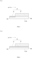
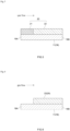
- a catalyst support portion 10, 10A includes a catalyst support portion 20 provided on the surface and/or inside of each partition 16 in the cell 15, which is an exhaust gas passage.
- the catalyst support portion 20 includes: a catalyst metal direct support portion 24 provided in at least the upstream region of a predetermined length from an upstream end 16A; and a catalyst coat portion 22 that is not provided in the upstream region of the predetermined length and is provided only in a downstream region downstream of the upstream region.
- the exhaust gas flows from the left side to the right side (see arrows in the drawings).
- the left end of the base material 11 (partitions 16) in the drawings is the upstream end 16A and the right end is the downstream end 16B.
- the catalyst metal direct support portion 24 is provided only in the upstream region of the predetermined length from the upstream end 16A.
- the catalyst metal direct support portion 24 is provided also in at least a partial area of the downstream region in which the catalyst coat portion 22 is provided (an entire region from the upstream end 16A to the downstream end 16B in the embodiment shown in Fig. 4 ).
- the catalyst coat portion 22 is not provided in the upstream region of the predetermined length, and is provided only in the downstream region downstream of the upstream region.
- the heat capacity of the catalyst support portion 20 in the upstream region decreases, thereby improving the warm-up performance.
- the temperature rise performance of the catalyst metal direct support portion in the upstream region improves, and the purifying performance of the exhaust gas during cold start and cold run can be further enhanced.
- the embodiment shown in Fig. 3 which has smaller thermal capacity is preferable.
- the catalyst coat portion 22 at least includes a catalyst metal that functions as a catalyst capable of oxidizing or reducing at least one exhaust gas component and an inorganic carrier that supports the catalyst metal.
- the catalyst metal examples include metals belonging to platinum group elements such as palladium (Pd), rhodium (Rh), and platinum (Pt) or other metals that function as oxidization catalysts or reduction catalysts.
- Pd and Pt have excellent purifying performance (oxidation purifying performance) for carbon monoxide and hydrocarbon
- Rh has excellent purifying performance (reduction purifying performance) for NO x .
- they are particularly preferable catalyst metals.
- metals such as barium (Ba), strontium (Sr), other alkaline earth metals, alkali metals, transition metals, and the like may be used as cocatalyst components.
- the mean particle diameter of the catalyst metal by electron microscopy may be preferably 0.5 nm to 50 nm, more preferably 1 nm to 20 nm, but is not particularly limited.
- the carrier that supports the catalyst metal and constitutes the catalyst coat portion 22 is not particularly limited as long as it can support the catalyst metal, and can be a support made of known inorganic compound particles.
- the carrier include inorganic compound particles (so-called an OSC material) having oxygen storage capacity (OSC) such as ceria (CeO 2 ) and a composite oxide (e.g., a ceria-zirconia composite oxide (CZ or ZC composite oxide)) containing ceria; and oxide particles such as alumina (Al 2 O 3 ), titania (TiO 2 ), zirconia (ZrO 2 ), and silica (SiO 2 ).
- the carriers may be used alone or in combination of two or more of them.
- the OSC material may function as a cocatalyst for purification of exhaust gas, and thus, a carrier containing the OSC material is preferable.
- the OSC materials such as ceria and a ceria-zirconia composite oxide, containing trace amounts of oxides that contains yttrium (Y), lanthanum (La), niobium (Nb), praseodymium (Pr), and other rare earth elements are suitable because they improve heat resistance.
- the catalyst coat portion 22 may further contain components other than the catalyst metal components and the carrier, such as a binder, a cocatalyst component, and other additives.
- alumina, silica, and the like can be used as in known catalyst coat portion of this type.
- the cocatalyst component include metals such as Ba and Sr as described above.
- the content of the catalyst metal in the catalyst coat portion 22 is not particularly limited.
- the content may be 0.01 mass% to 10 mass%, preferably 0.1 mass% to 5 mass% relative to the entire mass of the carrier contained in the catalyst coat portion 22.
- the catalyst coat portion 22 may have a simple monolayer structure, as schematically shown in Figs. 3 and 4 , or a multilayer structure with two or more layers in which types of catalyst metals and/or carriers, their blending ratios, and the like are different from each other.
- the thickness and length of the catalyst coat portion 22 may be determined, as appropriate, according to the size of the cells 15 of the base material 11, 11A, the flow rate of the exhaust gas introduced into the exhaust gas passage, and the like.
- the thickness of the catalyst coat portion 22 can be 1 ⁇ m to 500 ⁇ m.
- the catalyst metal direct support portion 24 is part of the catalyst support portion, which is configured to be directly supported on the base material 11, 11A without using the carrier to reduce the heat capacity compared to the catalyst coat portion 22.
- the type of the catalyst metal used in the catalyst metal direct support portion 24 may be the same as or different from that in the catalyst coat portion 22.
- at least one of Pd, Pt, or Rh such as used in Examples described below is preferably supported on the catalyst metal direct support portion 24.
- Pd and/or Pt is supported as the catalyst metal
- the purifying performance of exhaust gas during cold start and cold run especially the purifying performance of the exhaust gas components purified by oxidation, such as HC and CO, can be improved.
- Rh is supported as the catalyst metal
- the purifying performance of the exhaust gas components purified by reduction, such as NO x during cold start and cold run can be improved.
- Components other than catalytic metals can be contained as long as the desired low heat capacity is maintained.
- alkaline earth metals such as barium (Ba) and strontium (Sr) can be contained (for example, in about 1 mass% to about 20 mass% relative to the entire catalyst support portion 20). This can reduce sintering of Pd and maintain catalytic activity of Pd.
- the mean particle diameter of the catalyst metal by electron microscopy may be preferably 0.5 nm to 50 nm, more preferably 1 nm to 20 nm, but is not particularly limited.
- the content of the catalyst metal per unit volume (1 L) in the entire exhaust gas purification catalyst 10, 10A is suitably about 0.1 g/L to about 5 g/L, preferably about 0.2 g/L to about 2 g/L.
- the content of the catalyst metal is too high, it is not desirable in terms of cost, and when the content of the catalyst metal is too low, the exhaust gas purifying performance is not desirable.
- the 1 L When the 1 L is referred to as a catalyst volume herein, it refers to a bulk volume of 1 L, which includes the net volume of the base material 11, 11A plus the volume of the voids in the cells 15.
- the catalyst coat portion 22 and the catalyst metal direct support portion 24 in the exhaust gas purification catalyst 10, 10A disclosed herein can be formed by the same method of forming the catalyst coat portion of the conventional exhaust gas purification catalyst.
- the catalyst coat portion 22 can be easily produced by the washcoat method or other methods conventionally used to form this type of the catalyst coat portion.
- aqueous slurry containing a raw material compound e.g., water-soluble metal salt such as Pd nitrate or Rh nitrate
- carrier particles made of ceramics such as alumina, zirconia, and OSC materials
- a cocatalyst component such as barium sulfate
- an additive such as a thickener
- the aqueous slurry is fired at a predetermined temperature for a predetermined time.
- the catalyst coat portion 22 can be formed on the base material 11, 11A.
- the firing conditions of the washcoated slurry vary according to the shape and size of the base material or carrier, and typically, an intended catalyst coat portion 22 can be formed by firing at about 400°C to about 1000°C for about 1 hour to about 5 hours.
- the catalyst metal direct support portion 24 can also be formed by the washcoat method in the same manner as forming the catalyst coat portion 22.
- aqueous slurry containing a raw material compound e.g., a water-soluble metal salt such as Pd nitrate or Rh nitrate
- a thickener is coated from the upstream end 16A of the base material 11, 11A by the well-known washcoat method or the like.
- the thickness of the catalyst metal direct support portion 24 formed in the direction of the thickness of the partitions 16 of the base material 11, 11A can be adjusted by appropriately adjusting the viscosity of the slurry used.
- the viscosity measured with a commercially available cone-plate viscometer at a rotation speed of 1 rpm to 100 rpm, room temperature (25°C), and shear rate of 380 s -1 is suitably about 10 mPa to about 1000 mPa, preferably about 100 mPa to about 800 mPa.
- the viscosity is preferably about 200 mPa to about 600 mPa.
- a thickener to adjust the viscosity of this type of slurry for washcoat a conventionally known compound can be used.
- the thickener used include: water-soluble polymers such as polyvinyl alcohol, ethylene glycol, and propylene glycol, cellulose derivatives such as hydroxyethyl cellulose, carboxymethyl cellulose, and methyl cellulose, and polysaccharides such as pectin and xanthan gum.
- the aqueous slurry is fired at a predetermined temperature for a predetermined time.
- the catalyst metal direct support portion 24 can be formed on the base material 11, 11A.
- the firing conditions of the washcoated slurry vary according to the shape and size of the base material or carrier, and typically, an intended catalyst metal direct support portion 24 can be formed by firing at about 400°C to about 1000°C for about 1 hour to about 5 hours.
- it can be wash-coated with the slurry for forming the catalyst metal direct support portion and wash-coated with the slurry for forming the catalyst coat portion, and then fired at the same time.
- the upstream region of the predetermined length (i.e., an area in which the catalyst coat portion 22 is not provided) is not particularly limited in length as long as the intended decrease in heat capacity is achieved.
- the upstream region is provided in a region of a length which is suitably 20% or more, preferably 30% or more when the overall length of the cell 15 (exhaust gas passage) of the base material 11, 11Ais 100%.
- the length of the upstream region is suitably 50% or less, preferably 40% or less of the overall length.
- each of the base materials had a length in the major axis direction (exhaust gas flowing direction) of 50 mm, a capacity of 0.551 L, a diameter of 118.4 mm, and about 600 cells with a square cross section.
- the thickness of the partition was about 4 mils to about 5 mils (1 mil is 1/1000 inch).
- honeycomb-shaped straight-flow type exhaust gas purification catalyst including a catalyst support portion 20, shown schematically in any of Figs. 3 to 6 , was produced using the base material.
- the specific method is as follows.
- a Fr region catalyst coat portion 21 was formed as an upstream region of a length which is 30% from an upstream end relative to 100% of the overall length in the exhaust gas flowing direction (the direction shown by the arrow in the drawing), an Rr region catalyst coat portion 22 was formed in a downstream region of a length which is the remaining 70%, and a catalyst metal direct support portion was not formed.
- an exhaust gas purification catalyst of Comparative Example 1 was produced (see Fig. 5 ).
- alumina carrier particles containing about 1 wt% to about 10wt% La 2 O 3 and alumina-based sol (binder) were added to and suspended in an aqueous solution of palladium nitrate.
- a slurry 1 for forming a catalyst coat portion was prepared.
- the slurry 1 was then poured into the cells from the upstream end of the base material 1, and unnecessary substances were blown away with a blower.
- a Pd layer containing Pd as a catalyst metal was formed on the wall surface (partition surface) of the base material.
- the resultant was then dried in a dryer set at 120°C for two hours to remove moisture, and then transferred to an electric furnace and fired at 500°C for two hours.
- a Fr region catalyst coat portion 21 containing Pd was formed in the upstream region of a length which was 30% from the upstream end relative to 100% of the overall length.
- alumina carrier particles containing about 1 wt% to about 10 wt% La 2 O 3 , CZ compound particles containing CeO 2 as an OSC material in a content of 15 wt% to 40 wt% and the reminder ZrO 2 , and alumina-based sol (binder) were added to and suspended in an aqueous solution of rhodium nitrate.
- a slurry 2 for forming a catalyst coat portion was prepared.
- the slurry 2 was then poured into the cells from the downstream end of the base material 1, and unnecessary substances were blown away with a blower.
- a Rh layer containing Rh as a catalyst metal was formed on the wall surface (partition surface) of the base material.
- the resultant was then dried in a dryer set at 120°C for two hours to remove moisture, and then transferred to an electric furnace and fired at 500°C for two hours.
- an Rr region catalyst coat portion 22 containing Rh was formed in the downstream region of a length which was 70% from the downstream end relative to 100% of the overall length (see Fig. 5 ).
- the amount of the catalyst metal supported per 1 L of the catalyst volume in Comparative Example 1 was about 2 g/L, and the amount of Rh supported in the Rr region catalyst coat portion 22 was about 0.15 g/L.
- Alumina carrier particles containing about 1 wt% to about 10 wt% La 2 O 3 , CZ compound particles containing CeO 2 as an OSC material in a content of 15 wt% to 40 wt% and the reminder ZrO 2 , and alumina-based sol (binder) were added to and suspended in an aqueous solution containing palladium nitrate and rhodium nitrate.
- a slurry 3 for forming a catalyst coat portion was prepared.
- the slurry 3 was then poured into the cells from the downstream end of the base material 1, and unnecessary substances were blown away with a blower.
- a Pd-Rh layer containing Pd and Rh as catalyst metals was formed on the wall surface (partition surface) of the base material.
- the resultant was then dried in a dryer set at 120°C for two hours to remove moisture, and then transferred to an electric furnace and fired at 500°C for two hours.
- an Rr region catalyst coat portion 22 containing both Pd and Rh was formed in the downstream region of a length which was 70% from the downstream end relative to 100% of the overall length (see Fig. 6 ).
- a catalyst support portion was not formed in the upstream region of a length which was 30% from the upstream end relative to 100% of the overall length in the exhaust gas flowing direction.
- the amount of Pd supported is about 2 g/L
- the amount of Rh supported is about 0.15 g/L.
- Hydroxyethyl cellulose was added as a thickener to an aqueous solution of palladium nitrate to prepare a coating solution for forming a catalyst metal direct support portion.
- the amount of the thickener added was adjusted to have a viscosity of 300 mPa, measured at a shear velocity of 380 s -1 at 25°C by using a cone-plate viscometer manufactured by Toki Sangyo Co., Ltd. when the number of revolutions is changed in the range of 1 rpm to 100 rpm.
- the coating solution obtained was poured into an upstream region of a length which was 30% from the upstream end relative to 100% of the overall length of the inside of each cell from the upstream end of the base material 1, and unnecessary substances were blown away with a blower.
- a region in which Pd was directly disposed was formed inside the partition of the base material (a region of a depth which was about 30% from the surface of the partition relative to 100% of the overall thickness).
- the resultant was then dried in a dryer set at 120°C for two hours to remove moisture, and then transferred to an electric furnace and fired at 500°C for two hours.
- a catalyst metal direct support portion 24 containing Pd in an upstream region of a length which was 30% from the upstream end relative to 100% of the overall length was formed (see Fig. 3 ).
- a coating solution for forming the catalyst metal direct support portion was poured over the entire length from the upstream end to the lower end inside each cell, and unnecessary substances were blown away with a blower. Thus, a region in which Pd was directly disposed was formed inside the partition of the base material (a region of a depth which was about 30% from the surface of the partition relative to 100% of the overall thickness). The resultant was then dried in a dryer set at 120°C for two hours to remove moisture, and then transferred to an electric furnace and fired at 500°C for two hours. Thus, a catalyst metal direct support portion 24 containing Pd was formed over the overall length of each cell (see Fig. 4 ).
- Comparative Example 3 the base material 2 was used.
- an exhaust gas purification catalyst in which a Fr region catalyst coat portion 21 containing Pd was formed in an upstream region of a length which was 30% from the upstream end relative to 100% of the overall length, and a Rh region catalyst coat portion 22 containing Rh was formed in a downstream region of a length which was 70% from the upstream end was prepared ( Fig. 5 ).
- the amount of the catalyst metal supported per 1 L of the catalyst volume in Comparative Example 3 the amount of Pd supported in the Fr region catalyst coat portion 21 was about 2 g/L, and the amount of Rh supported in the Rr region catalyst coat portion 22 was about 0.15 g/L.
- Example 3 the base material 2 was used.
- an exhaust gas purification catalyst in which a catalyst metal direct support portion 24 containing Pd was formed in an upstream region of a length which was 30% from the upstream end relative to 100% of the overall length, and an Rr region catalyst coat portion 22 containing Rh was formed in a downstream region of a length which was 70% from the upstream end was prepared ( Fig. 3 ).
- the amount of the catalyst metal supported per 1 L of the catalyst volume in Example 3 the amount of Pd supported in the catalyst metal direct support portion 24, which was the Fr region, was about 2 g/L, and the amount of Rh supported in the Rr region catalyst coat portion 22 was about 0.15 g/L.
- Comparative Example 4 the base material 3 was used.
- an exhaust gas purification catalyst in which a Fr region catalyst coat portion 21 containing Pd was formed in an upstream region of a length which was 30% from the upstream end relative to 100% of the overall length, and an Rr region catalyst coat portion 22 containing Rh was formed in a downstream region of a length which was 70% from the upstream end was prepared ( Fig. 5 ).
- the amount of the catalyst metal supported per 1 L of the catalyst volume in Comparative Example 4 the amount of Pd supported in the Fr region catalyst coat portion 21 was about 2 g/L, and the amount of Rh supported in the Rr region catalyst coat portion 22 was about 0.15 g/L.
- Example 4 the base material 3 was used.
- an exhaust gas purification catalyst in which a catalyst metal direct support portion 24 containing Pd was formed in an upstream region of a length which was 30% from the upstream end relative to 100% of the overall length, and an Rr region catalyst coat portion 22 containing Rh was formed in a downstream region of a length which was 70% from the upstream end was prepared ( Fig. 3 ).
- the amount of the catalyst metal supported per 1 L of the catalyst volume in Example 4 the amount of Pd supported in the catalyst metal direct support portion 24, which was the Fr region, was about 2 g/L, and the amount of Rh supported in the Rr region catalyst coat portion 22 was about 0.15 g/L.
- a warm-up characteristic evaluation test was performed using eight types of exhaust gas purification catalysts obtained.
- one of the exhaust gas purification catalysts was connected to an exhaust system (exhaust pipe) of a gasoline engine (inline four-cylinder engine) installed on a test stand.
- a bypass pipe to which the exhaust gas purification catalyst was not connected was provided in parallel with the exhaust gas purification catalyst, so that the exhaust gas exhausted from the gasoline engine was switchable to flow toward the exhaust gas purification catalyst or toward the bypass pipe by switching a valve.
- the temperature of the exhaust gas introduced into the exhaust gas purification catalyst was then adjusted to achieve the predetermined conditions.
- the air-fuel ratio was set to stoichiometric (here 14.6), exhaust gas was produced at an intake air volume of 22 g/sec, and exhaust gas at about 520°C was introduced into the exhaust gas purification catalyst connected to the exhaust system for preheat treatment.
- the valve was then switched and the exhaust gas was exhausted through the bypass pipe and cooling air was introduced into the exhaust gas purification catalyst and cooled until the temperature of the air passing through the catalyst reached about 60°C.
- the valve was then switched again, and when the temperature of the exhaust gas purification catalyst reached 60°C, the introduction of the exhaust gas at 500°C into the exhaust gas purification catalyst was started, and the HC purification rate was measured. The number of seconds until the HC purification rate reached 50% was then measured and used as an index for the warm-up characteristic evaluation test.
- the results were shown in the graphs of Figs. 7 to 9 .
- the results of Comparative Examples 1 to 2 and Examples 1 to 2 using the base material 1 are shown in Fig. 7 .
- the results of Comparative Example 3 and Example 3 using the base material 2 are shown in Fig. 8 .
- the results of Comparative Example 4 and Example 4 using the above base material 3 are shown in Fig. 9 .
Landscapes
- Chemical & Material Sciences (AREA)
- Engineering & Computer Science (AREA)
- Chemical Kinetics & Catalysis (AREA)
- Materials Engineering (AREA)
- Organic Chemistry (AREA)
- Combustion & Propulsion (AREA)
- Health & Medical Sciences (AREA)
- Toxicology (AREA)
- Mechanical Engineering (AREA)
- General Engineering & Computer Science (AREA)
- Environmental & Geological Engineering (AREA)
- Analytical Chemistry (AREA)
- General Chemical & Material Sciences (AREA)
- Oil, Petroleum & Natural Gas (AREA)
- Biomedical Technology (AREA)
- Ceramic Engineering (AREA)
- Catalysts (AREA)
- Exhaust Gas Treatment By Means Of Catalyst (AREA)
- Exhaust Gas After Treatment (AREA)
Applications Claiming Priority (2)
| Application Number | Priority Date | Filing Date | Title |
|---|---|---|---|
| JP2021101313A JP7729739B2 (ja) | 2021-06-18 | 2021-06-18 | 排ガス浄化触媒 |
| PCT/JP2022/023454 WO2022264936A1 (ja) | 2021-06-18 | 2022-06-10 | 排ガス浄化触媒 |
Publications (2)
| Publication Number | Publication Date |
|---|---|
| EP4338833A1 true EP4338833A1 (de) | 2024-03-20 |
| EP4338833A4 EP4338833A4 (de) | 2024-10-16 |
Family
ID=84527526
Family Applications (1)
| Application Number | Title | Priority Date | Filing Date |
|---|---|---|---|
| EP22824926.4A Pending EP4338833A4 (de) | 2021-06-18 | 2022-06-10 | Abgasreinigungskatalysator |
Country Status (4)
| Country | Link |
|---|---|
| US (1) | US20240278217A1 (de) |
| EP (1) | EP4338833A4 (de) |
| JP (1) | JP7729739B2 (de) |
| WO (1) | WO2022264936A1 (de) |
Families Citing this family (1)
| Publication number | Priority date | Publication date | Assignee | Title |
|---|---|---|---|---|
| JP6986123B1 (ja) * | 2020-08-07 | 2021-12-22 | 株式会社キャタラー | 排ガス浄化用触媒 |
Family Cites Families (7)
| Publication number | Priority date | Publication date | Assignee | Title |
|---|---|---|---|---|
| JP2003200062A (ja) | 2001-10-26 | 2003-07-15 | Denso Corp | 車両用触媒 |
| JP2009138667A (ja) | 2007-12-07 | 2009-06-25 | Toyota Motor Corp | 排ガス浄化用触媒装置 |
| JP2009275559A (ja) | 2008-05-13 | 2009-11-26 | Toyota Motor Corp | 電気加熱式触媒装置 |
| JP5757274B2 (ja) | 2012-06-20 | 2015-07-29 | トヨタ自動車株式会社 | 電気加熱式触媒コンバーター |
| JP2020179348A (ja) | 2019-04-25 | 2020-11-05 | トヨタ自動車株式会社 | 排ガス浄化用触媒 |
| JP7372052B2 (ja) | 2019-05-15 | 2023-10-31 | 株式会社キャタラー | 排ガス浄化触媒装置 |
| JP7405601B2 (ja) | 2019-12-24 | 2023-12-26 | 東芝テック株式会社 | 保守員管理システム |
-
2021
- 2021-06-18 JP JP2021101313A patent/JP7729739B2/ja active Active
-
2022
- 2022-06-10 EP EP22824926.4A patent/EP4338833A4/de active Pending
- 2022-06-10 WO PCT/JP2022/023454 patent/WO2022264936A1/ja not_active Ceased
- 2022-06-10 US US18/569,653 patent/US20240278217A1/en active Pending
Also Published As
| Publication number | Publication date |
|---|---|
| US20240278217A1 (en) | 2024-08-22 |
| EP4338833A4 (de) | 2024-10-16 |
| JP7729739B2 (ja) | 2025-08-26 |
| WO2022264936A1 (ja) | 2022-12-22 |
| JP2023000472A (ja) | 2023-01-04 |
Similar Documents
| Publication | Publication Date | Title |
|---|---|---|
| JP5447757B2 (ja) | 触媒被覆された粒子フィルタ及びその製造方法並びにその使用 | |
| CN111132759B (zh) | 具有改善热稳定性的用于汽油废气应用的twc催化剂 | |
| CN107073447B (zh) | 废气净化用催化剂 | |
| CN102711960B (zh) | 分区催化烟灰过滤器 | |
| KR101838558B1 (ko) | NOx 트랩 | |
| CN107073463B (zh) | 废气净化用催化剂 | |
| JP6611611B2 (ja) | 排ガス浄化用触媒 | |
| CN105983339B (zh) | 催化转换器 | |
| US10987658B2 (en) | Low washcoat loading single layer catalysts for gasoline exhaust gas applications | |
| CN101489670B (zh) | 排气净化用催化剂 | |
| CN107288728A (zh) | 催化转换器 | |
| WO2001036097A1 (en) | Catalyst and method for preparation thereof | |
| CN108778491A (zh) | 废气净化用催化剂 | |
| CN115996793A (zh) | 排气净化用催化剂 | |
| CN111148571A (zh) | 排气净化用催化剂 | |
| CN110997141A (zh) | 排气净化用催化剂 | |
| CN111841534A (zh) | 废气净化用催化剂 | |
| CN112808279B (zh) | 排气净化用催化剂 | |
| JP6997838B1 (ja) | 排ガス浄化用触媒 | |
| EP4338833A1 (de) | Abgasreinigungskatalysator | |
| JP6204023B2 (ja) | 排ガス浄化用触媒 | |
| JP3827143B2 (ja) | 排ガス浄化用触媒 | |
| EP4180120A1 (de) | Abgasreinigungskatalysator | |
| JP2025513795A (ja) | ガソリン微粒子フィルタを製造するための方法 | |
| JP2004230226A (ja) | 自動車用触媒 |
Legal Events
| Date | Code | Title | Description |
|---|---|---|---|
| STAA | Information on the status of an ep patent application or granted ep patent |
Free format text: STATUS: THE INTERNATIONAL PUBLICATION HAS BEEN MADE |
|
| PUAI | Public reference made under article 153(3) epc to a published international application that has entered the european phase |
Free format text: ORIGINAL CODE: 0009012 |
|
| STAA | Information on the status of an ep patent application or granted ep patent |
Free format text: STATUS: REQUEST FOR EXAMINATION WAS MADE |
|
| 17P | Request for examination filed |
Effective date: 20231213 |
|
| AK | Designated contracting states |
Kind code of ref document: A1 Designated state(s): AL AT BE BG CH CY CZ DE DK EE ES FI FR GB GR HR HU IE IS IT LI LT LU LV MC MK MT NL NO PL PT RO RS SE SI SK SM TR |
|
| DAV | Request for validation of the european patent (deleted) | ||
| DAX | Request for extension of the european patent (deleted) | ||
| A4 | Supplementary search report drawn up and despatched |
Effective date: 20240918 |
|
| RIC1 | Information provided on ipc code assigned before grant |
Ipc: F01N 3/10 20060101ALI20240912BHEP Ipc: B01J 37/02 20060101ALI20240912BHEP Ipc: B01J 35/33 20240101ALI20240912BHEP Ipc: B01J 35/00 20240101ALI20240912BHEP Ipc: B01J 23/44 20060101ALI20240912BHEP Ipc: F01N 3/28 20060101ALI20240912BHEP Ipc: F01N 3/24 20060101ALI20240912BHEP Ipc: F01N 3/20 20060101ALI20240912BHEP Ipc: F01N 3/18 20060101ALI20240912BHEP Ipc: B01J 27/224 20060101ALI20240912BHEP Ipc: B01D 53/94 20060101ALI20240912BHEP Ipc: B01J 23/46 20060101AFI20240912BHEP |