EP4338841A1 - Genverstärkungschip, vorrichtung zur genverstärkung und vorrichtung zur analyse von biopartikeln - Google Patents
Genverstärkungschip, vorrichtung zur genverstärkung und vorrichtung zur analyse von biopartikeln Download PDFInfo
- Publication number
- EP4338841A1 EP4338841A1 EP23156797.5A EP23156797A EP4338841A1 EP 4338841 A1 EP4338841 A1 EP 4338841A1 EP 23156797 A EP23156797 A EP 23156797A EP 4338841 A1 EP4338841 A1 EP 4338841A1
- Authority
- EP
- European Patent Office
- Prior art keywords
- passage
- layer
- gene amplification
- channel
- cover
- Prior art date
- Legal status (The legal status is an assumption and is not a legal conclusion. Google has not performed a legal analysis and makes no representation as to the accuracy of the status listed.)
- Pending
Links
Images














Classifications
-
- B—PERFORMING OPERATIONS; TRANSPORTING
- B01—PHYSICAL OR CHEMICAL PROCESSES OR APPARATUS IN GENERAL
- B01L—CHEMICAL OR PHYSICAL LABORATORY APPARATUS FOR GENERAL USE
- B01L3/00—Containers or dishes for laboratory use, e.g. laboratory glassware; Droppers
- B01L3/50—Containers for the purpose of retaining a material to be analysed, e.g. test tubes
- B01L3/502—Containers for the purpose of retaining a material to be analysed, e.g. test tubes with fluid transport, e.g. in multi-compartment structures
-
- B—PERFORMING OPERATIONS; TRANSPORTING
- B01—PHYSICAL OR CHEMICAL PROCESSES OR APPARATUS IN GENERAL
- B01L—CHEMICAL OR PHYSICAL LABORATORY APPARATUS FOR GENERAL USE
- B01L3/00—Containers or dishes for laboratory use, e.g. laboratory glassware; Droppers
- B01L3/50—Containers for the purpose of retaining a material to be analysed, e.g. test tubes
- B01L3/502—Containers for the purpose of retaining a material to be analysed, e.g. test tubes with fluid transport, e.g. in multi-compartment structures
- B01L3/5027—Containers for the purpose of retaining a material to be analysed, e.g. test tubes with fluid transport, e.g. in multi-compartment structures by integrated microfluidic structures, i.e. dimensions of channels and chambers are such that surface tension forces are important, e.g. lab-on-a-chip
- B01L3/50273—Containers for the purpose of retaining a material to be analysed, e.g. test tubes with fluid transport, e.g. in multi-compartment structures by integrated microfluidic structures, i.e. dimensions of channels and chambers are such that surface tension forces are important, e.g. lab-on-a-chip characterised by the means or forces applied to move the fluids
-
- C—CHEMISTRY; METALLURGY
- C12—BIOCHEMISTRY; BEER; SPIRITS; WINE; VINEGAR; MICROBIOLOGY; ENZYMOLOGY; MUTATION OR GENETIC ENGINEERING
- C12Q—MEASURING OR TESTING PROCESSES INVOLVING ENZYMES, NUCLEIC ACIDS OR MICROORGANISMS; COMPOSITIONS OR TEST PAPERS THEREFOR; PROCESSES OF PREPARING SUCH COMPOSITIONS; CONDITION-RESPONSIVE CONTROL IN MICROBIOLOGICAL OR ENZYMOLOGICAL PROCESSES
- C12Q1/00—Measuring or testing processes involving enzymes, nucleic acids or microorganisms; Compositions therefor; Processes of preparing such compositions
- C12Q1/68—Measuring or testing processes involving enzymes, nucleic acids or microorganisms; Compositions therefor; Processes of preparing such compositions involving nucleic acids
- C12Q1/6844—Nucleic acid amplification reactions
- C12Q1/686—Polymerase chain reaction [PCR]
-
- B—PERFORMING OPERATIONS; TRANSPORTING
- B01—PHYSICAL OR CHEMICAL PROCESSES OR APPARATUS IN GENERAL
- B01L—CHEMICAL OR PHYSICAL LABORATORY APPARATUS FOR GENERAL USE
- B01L3/00—Containers or dishes for laboratory use, e.g. laboratory glassware; Droppers
- B01L3/50—Containers for the purpose of retaining a material to be analysed, e.g. test tubes
- B01L3/502—Containers for the purpose of retaining a material to be analysed, e.g. test tubes with fluid transport, e.g. in multi-compartment structures
- B01L3/5027—Containers for the purpose of retaining a material to be analysed, e.g. test tubes with fluid transport, e.g. in multi-compartment structures by integrated microfluidic structures, i.e. dimensions of channels and chambers are such that surface tension forces are important, e.g. lab-on-a-chip
- B01L3/502715—Containers for the purpose of retaining a material to be analysed, e.g. test tubes with fluid transport, e.g. in multi-compartment structures by integrated microfluidic structures, i.e. dimensions of channels and chambers are such that surface tension forces are important, e.g. lab-on-a-chip characterised by interfacing components, e.g. fluidic, electrical, optical or mechanical interfaces
-
- B—PERFORMING OPERATIONS; TRANSPORTING
- B01—PHYSICAL OR CHEMICAL PROCESSES OR APPARATUS IN GENERAL
- B01L—CHEMICAL OR PHYSICAL LABORATORY APPARATUS FOR GENERAL USE
- B01L3/00—Containers or dishes for laboratory use, e.g. laboratory glassware; Droppers
- B01L3/50—Containers for the purpose of retaining a material to be analysed, e.g. test tubes
- B01L3/502—Containers for the purpose of retaining a material to be analysed, e.g. test tubes with fluid transport, e.g. in multi-compartment structures
- B01L3/5027—Containers for the purpose of retaining a material to be analysed, e.g. test tubes with fluid transport, e.g. in multi-compartment structures by integrated microfluidic structures, i.e. dimensions of channels and chambers are such that surface tension forces are important, e.g. lab-on-a-chip
- B01L3/502746—Containers for the purpose of retaining a material to be analysed, e.g. test tubes with fluid transport, e.g. in multi-compartment structures by integrated microfluidic structures, i.e. dimensions of channels and chambers are such that surface tension forces are important, e.g. lab-on-a-chip characterised by the means for controlling flow resistance, e.g. flow controllers, baffles or throttle valves
-
- B—PERFORMING OPERATIONS; TRANSPORTING
- B01—PHYSICAL OR CHEMICAL PROCESSES OR APPARATUS IN GENERAL
- B01L—CHEMICAL OR PHYSICAL LABORATORY APPARATUS FOR GENERAL USE
- B01L3/00—Containers or dishes for laboratory use, e.g. laboratory glassware; Droppers
- B01L3/50—Containers for the purpose of retaining a material to be analysed, e.g. test tubes
- B01L3/508—Rigid containers without fluid transport within
- B01L3/5085—Rigid containers without fluid transport within for multiple samples, e.g. microtitration plates
- B01L3/50851—Rigid containers without fluid transport within for multiple samples, e.g. microtitration plates specially adapted for heating or cooling samples
-
- B—PERFORMING OPERATIONS; TRANSPORTING
- B01—PHYSICAL OR CHEMICAL PROCESSES OR APPARATUS IN GENERAL
- B01L—CHEMICAL OR PHYSICAL LABORATORY APPARATUS FOR GENERAL USE
- B01L3/00—Containers or dishes for laboratory use, e.g. laboratory glassware; Droppers
- B01L3/50—Containers for the purpose of retaining a material to be analysed, e.g. test tubes
- B01L3/508—Rigid containers without fluid transport within
- B01L3/5085—Rigid containers without fluid transport within for multiple samples, e.g. microtitration plates
- B01L3/50857—Rigid containers without fluid transport within for multiple samples, e.g. microtitration plates using arrays or bundles of open capillaries for holding samples
-
- B—PERFORMING OPERATIONS; TRANSPORTING
- B01—PHYSICAL OR CHEMICAL PROCESSES OR APPARATUS IN GENERAL
- B01L—CHEMICAL OR PHYSICAL LABORATORY APPARATUS FOR GENERAL USE
- B01L7/00—Heating or cooling apparatus; Heat insulating devices
- B01L7/52—Heating or cooling apparatus; Heat insulating devices with provision for submitting samples to a predetermined sequence of different temperatures, e.g. for treating nucleic acid samples
-
- G—PHYSICS
- G01—MEASURING; TESTING
- G01N—INVESTIGATING OR ANALYSING MATERIALS BY DETERMINING THEIR CHEMICAL OR PHYSICAL PROPERTIES
- G01N21/00—Investigating or analysing materials by the use of optical means, i.e. using sub-millimetre waves, infrared, visible or ultraviolet light
- G01N21/62—Systems in which the material investigated is excited whereby it emits light or causes a change in wavelength of the incident light
- G01N21/63—Systems in which the material investigated is excited whereby it emits light or causes a change in wavelength of the incident light optically excited
- G01N21/64—Fluorescence; Phosphorescence
-
- B—PERFORMING OPERATIONS; TRANSPORTING
- B01—PHYSICAL OR CHEMICAL PROCESSES OR APPARATUS IN GENERAL
- B01L—CHEMICAL OR PHYSICAL LABORATORY APPARATUS FOR GENERAL USE
- B01L2200/00—Solutions for specific problems relating to chemical or physical laboratory apparatus
- B01L2200/06—Fluid handling related problems
- B01L2200/0621—Control of the sequence of chambers filled or emptied
-
- B—PERFORMING OPERATIONS; TRANSPORTING
- B01—PHYSICAL OR CHEMICAL PROCESSES OR APPARATUS IN GENERAL
- B01L—CHEMICAL OR PHYSICAL LABORATORY APPARATUS FOR GENERAL USE
- B01L2200/00—Solutions for specific problems relating to chemical or physical laboratory apparatus
- B01L2200/06—Fluid handling related problems
- B01L2200/0647—Handling flowable solids, e.g. microscopic beads, cells, particles
- B01L2200/0652—Sorting or classification of particles or molecules
-
- B—PERFORMING OPERATIONS; TRANSPORTING
- B01—PHYSICAL OR CHEMICAL PROCESSES OR APPARATUS IN GENERAL
- B01L—CHEMICAL OR PHYSICAL LABORATORY APPARATUS FOR GENERAL USE
- B01L2200/00—Solutions for specific problems relating to chemical or physical laboratory apparatus
- B01L2200/06—Fluid handling related problems
- B01L2200/0647—Handling flowable solids, e.g. microscopic beads, cells, particles
- B01L2200/0663—Stretching or orienting elongated molecules or particles
-
- B—PERFORMING OPERATIONS; TRANSPORTING
- B01—PHYSICAL OR CHEMICAL PROCESSES OR APPARATUS IN GENERAL
- B01L—CHEMICAL OR PHYSICAL LABORATORY APPARATUS FOR GENERAL USE
- B01L2200/00—Solutions for specific problems relating to chemical or physical laboratory apparatus
- B01L2200/06—Fluid handling related problems
- B01L2200/0689—Sealing
-
- B—PERFORMING OPERATIONS; TRANSPORTING
- B01—PHYSICAL OR CHEMICAL PROCESSES OR APPARATUS IN GENERAL
- B01L—CHEMICAL OR PHYSICAL LABORATORY APPARATUS FOR GENERAL USE
- B01L2300/00—Additional constructional details
- B01L2300/06—Auxiliary integrated devices, integrated components
- B01L2300/0627—Sensor or part of a sensor is integrated
- B01L2300/0636—Integrated biosensor, microarrays
-
- B—PERFORMING OPERATIONS; TRANSPORTING
- B01—PHYSICAL OR CHEMICAL PROCESSES OR APPARATUS IN GENERAL
- B01L—CHEMICAL OR PHYSICAL LABORATORY APPARATUS FOR GENERAL USE
- B01L2300/00—Additional constructional details
- B01L2300/08—Geometry, shape and general structure
- B01L2300/0809—Geometry, shape and general structure rectangular shaped
- B01L2300/0819—Microarrays; Biochips
-
- B—PERFORMING OPERATIONS; TRANSPORTING
- B01—PHYSICAL OR CHEMICAL PROCESSES OR APPARATUS IN GENERAL
- B01L—CHEMICAL OR PHYSICAL LABORATORY APPARATUS FOR GENERAL USE
- B01L2300/00—Additional constructional details
- B01L2300/08—Geometry, shape and general structure
- B01L2300/0809—Geometry, shape and general structure rectangular shaped
- B01L2300/0829—Multi-well plates; Microtitration plates
-
- B—PERFORMING OPERATIONS; TRANSPORTING
- B01—PHYSICAL OR CHEMICAL PROCESSES OR APPARATUS IN GENERAL
- B01L—CHEMICAL OR PHYSICAL LABORATORY APPARATUS FOR GENERAL USE
- B01L2300/00—Additional constructional details
- B01L2300/08—Geometry, shape and general structure
- B01L2300/0861—Configuration of multiple channels and/or chambers in a single devices
-
- B—PERFORMING OPERATIONS; TRANSPORTING
- B01—PHYSICAL OR CHEMICAL PROCESSES OR APPARATUS IN GENERAL
- B01L—CHEMICAL OR PHYSICAL LABORATORY APPARATUS FOR GENERAL USE
- B01L2300/00—Additional constructional details
- B01L2300/08—Geometry, shape and general structure
- B01L2300/0861—Configuration of multiple channels and/or chambers in a single devices
- B01L2300/0864—Configuration of multiple channels and/or chambers in a single devices comprising only one inlet and multiple receiving wells, e.g. for separation, splitting
-
- B—PERFORMING OPERATIONS; TRANSPORTING
- B01—PHYSICAL OR CHEMICAL PROCESSES OR APPARATUS IN GENERAL
- B01L—CHEMICAL OR PHYSICAL LABORATORY APPARATUS FOR GENERAL USE
- B01L2300/00—Additional constructional details
- B01L2300/08—Geometry, shape and general structure
- B01L2300/0861—Configuration of multiple channels and/or chambers in a single devices
- B01L2300/0874—Three dimensional network
-
- B—PERFORMING OPERATIONS; TRANSPORTING
- B01—PHYSICAL OR CHEMICAL PROCESSES OR APPARATUS IN GENERAL
- B01L—CHEMICAL OR PHYSICAL LABORATORY APPARATUS FOR GENERAL USE
- B01L2300/00—Additional constructional details
- B01L2300/08—Geometry, shape and general structure
- B01L2300/0887—Laminated structure
-
- B—PERFORMING OPERATIONS; TRANSPORTING
- B01—PHYSICAL OR CHEMICAL PROCESSES OR APPARATUS IN GENERAL
- B01L—CHEMICAL OR PHYSICAL LABORATORY APPARATUS FOR GENERAL USE
- B01L2300/00—Additional constructional details
- B01L2300/12—Specific details about materials
-
- B—PERFORMING OPERATIONS; TRANSPORTING
- B01—PHYSICAL OR CHEMICAL PROCESSES OR APPARATUS IN GENERAL
- B01L—CHEMICAL OR PHYSICAL LABORATORY APPARATUS FOR GENERAL USE
- B01L2300/00—Additional constructional details
- B01L2300/16—Surface properties and coatings
- B01L2300/168—Specific optical properties, e.g. reflective coatings
-
- B—PERFORMING OPERATIONS; TRANSPORTING
- B01—PHYSICAL OR CHEMICAL PROCESSES OR APPARATUS IN GENERAL
- B01L—CHEMICAL OR PHYSICAL LABORATORY APPARATUS FOR GENERAL USE
- B01L2300/00—Additional constructional details
- B01L2300/18—Means for temperature control
- B01L2300/1861—Means for temperature control using radiation
-
- B—PERFORMING OPERATIONS; TRANSPORTING
- B01—PHYSICAL OR CHEMICAL PROCESSES OR APPARATUS IN GENERAL
- B01L—CHEMICAL OR PHYSICAL LABORATORY APPARATUS FOR GENERAL USE
- B01L2400/00—Moving or stopping fluids
- B01L2400/04—Moving fluids with specific forces or mechanical means
- B01L2400/0403—Moving fluids with specific forces or mechanical means specific forces
- B01L2400/0406—Moving fluids with specific forces or mechanical means specific forces capillary forces
-
- B—PERFORMING OPERATIONS; TRANSPORTING
- B01—PHYSICAL OR CHEMICAL PROCESSES OR APPARATUS IN GENERAL
- B01L—CHEMICAL OR PHYSICAL LABORATORY APPARATUS FOR GENERAL USE
- B01L2400/00—Moving or stopping fluids
- B01L2400/06—Valves, specific forms thereof
- B01L2400/0688—Valves, specific forms thereof surface tension valves, capillary stop, capillary break
-
- B—PERFORMING OPERATIONS; TRANSPORTING
- B82—NANOTECHNOLOGY
- B82Y—SPECIFIC USES OR APPLICATIONS OF NANOSTRUCTURES; MEASUREMENT OR ANALYSIS OF NANOSTRUCTURES; MANUFACTURE OR TREATMENT OF NANOSTRUCTURES
- B82Y5/00—Nanobiotechnology or nanomedicine, e.g. protein engineering or drug delivery
-
- C—CHEMISTRY; METALLURGY
- C12—BIOCHEMISTRY; BEER; SPIRITS; WINE; VINEGAR; MICROBIOLOGY; ENZYMOLOGY; MUTATION OR GENETIC ENGINEERING
- C12Q—MEASURING OR TESTING PROCESSES INVOLVING ENZYMES, NUCLEIC ACIDS OR MICROORGANISMS; COMPOSITIONS OR TEST PAPERS THEREFOR; PROCESSES OF PREPARING SUCH COMPOSITIONS; CONDITION-RESPONSIVE CONTROL IN MICROBIOLOGICAL OR ENZYMOLOGICAL PROCESSES
- C12Q1/00—Measuring or testing processes involving enzymes, nucleic acids or microorganisms; Compositions therefor; Processes of preparing such compositions
- C12Q1/68—Measuring or testing processes involving enzymes, nucleic acids or microorganisms; Compositions therefor; Processes of preparing such compositions involving nucleic acids
- C12Q1/6844—Nucleic acid amplification reactions
Definitions
- the following description relates to a gene amplification chip, an apparatus for gene amplification, and an apparatus for bio-particle analysis.
- the polymerase chain reaction is a technique for nucleic acid amplification, which has been widely used as a core technology in molecular biological diagnostic methods.
- the PCR is a method of detecting a target nucleic acid by amplifying a specific nucleic acid sequence, in which heating and cooling processes are repeated to activate or inhibit an enzyme for copying nucleic acid sequences.
- the PCR can detect the presence of a target DNA sequence in a sample, and research is conducted for simplifying the PCR process to reduce time and provide user convenience, and for manufacturing a PCR system in a compact size for use in point-of-care testing or individual diagnostic testing.
- Apparatuses consistent with the disclosure may include a gene amplification chip including: a chamber layer formed with a first passage and through holes formed on one side of the first passage; a cover layer disposed on one side of the chamber layer, the cover layer formed with a cover channel communicating with the first passage and the through holes of the chamber layer, wherein the cover channel, the first passage and the through holes allow passage of liquids in a divided manner; a bottom layer disposed on another side of the chamber layer, the bottom layer formed with a bottom channel communicating with the first passage and the through holes of the chamber layer; wherein the cover layer is further formed with an inlet communicating with the cover channel; and at least one of the cover layer and the bottom layer is formed with an outlet communicating with any one of the cover channel and the bottom channel.
- An embodiment further include an inlet in the cover layer formed to be closer to the plurality of through hole than to the first passage of the chamber layer.
- An embodiment may include the first passage and the cover channel are formed, wherein a sample solution flows from the inlet to the cover channel to be stored in the plurality of through holes, and oil having a lower surface tension than the sample solution flows from the inlet to the cover channel to the first passage and to the bottom channel.
- An embodiment may include the first passage having a larger cross-section than a cross-section of a cover channel region connected to the inlet.
- An embodiment may include the cross-section of the first passage being defined as a value obtained by multiplying a passage width by a passage length, and the cross-section of the cover channel region is defined as a value obtained by multiplying a channel height by a channel length, the passage length and the channel length are a same length in a same direction, and the passage width is greater than the channel height.
- An embodiment may include the cover channel having a larger cross-section than a cross-section of the through holes.
- An embodiment may include a cross-section of the through holes having any one of a hexagonal shape, a tetragonal shape, a triangular shape, and a circular shape.
- An embodiment may include the chamber layer further a second passage formed on a side opposite the first passage with the through holes formed therebetween.
- An embodiment may include the outlet formed to face the second passage.
- An embodiment may include the outlet formed in the cover layer.
- An embodiment may include the outlet formed in the bottom layer.
- An embodiment may include the chamber layer, the cover layer, and the bottom layer that are separately formed and subsequently joined together.
- An embodiment may include the chamber layer and the bottom layer that are integrally formed with each other to be joined to the cover layer.
- An embodiment may include each of the chamber layer, the cover layer, and the bottom layer being made of any one of silicon, metal, glass, and polymer.
- An embodiment may include the cover layer being made of a transparent material.
- An embodiment may include the first passage and the plurality of through holes in the chamber layer are separated by a non-through area, and cross sectional dimensions of the cover channel and the first passage are different from each other to flow liquid from the inlet through one of the first passage and the cover channel.
- An embodiment may include a gene amplification chip comprising a chamber layer formed with a first passage and through holes formed on one side of the first passage, a cover layer disposed on one side of the chamber layer, the cover layer being formed with a cover channel communicating with the first passage and the through holes of the chamber layer, wherein the cover channel, the first passage and the through holes allow passage of a sample solution in a divided manner, a bottom layer disposed on another side of the chamber layer, the bottom layer formed with a bottom channel communicating with the first passage and the through holes of the chamber layer, wherein the cover layer is further formed with an inlet communicating with the cover channel, at least one of the cover layer and the bottom layer is formed with an outlet communicating with any one of the cover channel and the bottom channel; a heat source configured to heat the gene amplification chip to allow gene amplification to occur in the sample solution; and a heat source controller configured to control temperature and time of heating by the heat source.
- An embodiment may include the heat source includes a light source configured to emit light; and a photothermal film attached to an outer surface of the bottom layer and configured to convert light, emitted by the light source, into heat to heat the gene amplification chip.
- An embodiment may include the heat source includes a thermoelement.
- An embodiment may include an apparatus for gene amplification in which gene amplification of a sample solution occurs; a detector configured to detect a signal generated in response to the occurrence of gene amplification of the sample solution; and a processor configured to analyze bio-particles based on the detected signal, wherein the apparatus for gene amplification may include: a gene amplification chip comprising a chamber layer formed with a first passage and through holes formed on one side of the first passage, a cover layer disposed on one side of the chamber layer, the cover layer formed with a cover channel communicating with the first passage and the through holes of the chamber layer, wherein the cover channel, the first passage and the through holes allow passage of the sample solution in a divided manner, a bottom layer disposed on another side of the chamber layer, the bottom layer formed witha bottom channel formed communicating with the first passage and the through holes of the chamber layer, wherein the cover layer is further formed with an inlet formed communicating with the cover channel, and at least one of the cover layer and the bottom layer is formed with an outlet communicating with any one of the cover
- An embodiment may include a processor calculating a concentration of the sample solution by measuring a number of through holes in which a fluorescence signal is observed.
- FIG. 1 is a perspective view of a gene amplification chip according to an embodiment of the present disclosure.
- FIG. 2 is an exploded perspective view of FIG. 1 .
- FIG. 3 is a plan view of FIG. 1 .
- FIG. 4 is a cross-sectional view taken along line 4-4 of FIG. 3 .
- FIG. 5 is a cross-sectional view taken along line 5-5 of FIG. 3 .
- FIG. 6 is a cross-sectional view taken along line 6-6 of FIG. 3 .
- a gene amplification chip 100 may include a chamber layer 110, a cover layer 120, a bottom layer 130, an inlet 140, and an outlet 150.
- the chamber layer 110 may include a first passage 111, and through holes 112 which are formed on one side of the first passage 111 and in which a sample solution is stored in a divided manner. The sample solution is divided among the through holes. In addition, as will be explained later, the sample solution may flow through the gene amplification chip by taking different flow paths.
- the chamber layer 110 may have a structure in which the first passage 111 and the through holes 112 are formed in a chamber base 110a.
- the chamber layer 110 may be formed in such a manner that with respect to the chamber base 110a disposed horizontally and parallel to the other layers, the first passage 111 is formed by vertically passing through the chamber base 110a, and the through holes 112 are also formed by vertically passing through the chamber base 110a.
- the chamber base 110 may have a constant thickness.
- the first passage 111 may be formed at an edge of one side of the chamber base 1 10a.
- the first passage 111 may be formed with a constant cross-section by passing through the chamber base 110a.
- the first passage 111 may be formed in various shapes, such as a tetragon, a circle, and the like. That is, the first passage 111 may be formed in the shape of a tetragonal column, a circular column, and the like.
- the first passage 111 may be formed so that oil injected through the inlet 140 may pass through the first passage 111 to flow to a bottom channel 131 of the bottom layer 130.
- the through holes 112 may be arranged in a group on one side of the first passage 111 to form a through-hole array 113.
- the through-hole array 113 may be disposed at the center of the chamber base 110a.
- the chamber base 110a may have a first non-through hole area 114 between the first passage 111 and the through-hole array 113.
- the through-hole array 113 may be spaced apart from the first passage 111 with the first non-through hole area 114 therebetween.
- the through holes 112 may be arranged at regular intervals in the X-axis and Y-axis directions.
- the through holes 112 may be arranged longer or shorter in the X-axis direction than in the Y-axis direction, or may be arranged in equal length in the X-axis direction than in the Y-axis direction, but the through holes 112 are not limited thereto.
- All the through holes 112 may have the same size.
- the respective through holes 112 may be formed with a constant cross-section by passing through the chamber base 110a.
- the cross-section of the through holes 112 may have various shapes, such as hexagon, tetragon, triangle, circle, and the like. That is, the through holes 112 may be formed in the shape of a hexagonal column, a tetragonal column, a circular column, and the like.
- Dozens of through holes 112 may be formed.
- the through holes 112 may have a volume of 10 pL or more. The number and volume of the through holes 112 are not limited thereto.
- the through holes 112 are formed so that a sample solution flowing through the inlet 140 to a cover channel 121 of the cover layer 120 may be contained therein in a divided manner.
- the chamber layer 110 may further include a second passage 115 formed on a side opposite the first passage 111 with the through holes 112 formed therebetween.
- the through-hole array 113 may be disposed between the first passage 111 and the second passage 115.
- the chamber base 110a may include a second non-through hole area 116 between the second passage 115 and the through-hole array 113.
- the through-hole array 113 may be spaced apart from the second passage 115 with the second non-through hole area 116 therebetween.
- the second passage 115 may be formed by vertically passing through the chamber base 110a.
- the second passage 115 may be formed with a constant cross-section by passing through the chamber base 1 10a.
- the second passage 115 may have the cross-section of various shapes, such as tetragon, circle, and the like. That is, the second passage 115 may be formed in the shape of a tetragonal column, a circular column, and the like.
- the second passage 115 may allow oil to flow between the cover channel 121 of the cover layer 120 and the bottom channel 131 of the bottom layer 130.
- the cover layer 120 may include the cover channel 121 formed to communicate with the first passage 111 and the through holes 112, and the cover layer 120 may be formed on one side of the chamber layer 110.
- the cover layer 120 may have the cover channel 121 formed on a lower surface thereof.
- the cover layer 120 may be formed over the chamber layer 110 while the cover channel 121 is directed toward the chamber layer 110.
- the cover channel 121 may be formed in a recessed shape extending from the first passage 111 to the second passage 115 and along the through-hole array 113. With respect to the cover layer 120 disposed horizontally and parallel to the other layers, the cover channel 121 may be formed to have a predetermined height from the first passage 111 to the second passage 115.
- a region of the cover channel 121 which extends from the first passage 111 to the first non-through hole area 114, may have the same length in the Y-axis direction as a length of the first passage 111 in the Y-axis direction.
- the cover channel 121 may be formed so that a sample solution injected through the inlet 140 may be stored in the through holes 112. After the sample solution is stored in the through holes 112, the cover channel 121 may allow the oil, injected through the inlet 140, to be filled therein such that an upper opening of the through holes 112 may be sealed by the oil.
- the cover channel 121 may have a larger cross-section than the cross-section of the through holes 112, thereby allowing the sample solution and the oil to flow smoothly.
- the bottom layer 130 may include the bottom channel 131 formed to communicate with the first passage 111 and the through holes 112, and may be formed on a side of the chamber layer 110 opposite the cover layer 120.
- the bottom layer 130 may have the bottom channel 131 formed on an upper surface thereof.
- the bottom layer 130 may be formed under the chamber layer 110 with the bottom channel 131 facing toward the chamber layer 110.
- the bottom channel 131 may be formed in a recessed shape extending from the first passage 111 to the second passage 115 and along the through-hole array 113. With respect to the bottom layer 130 disposed horizontally and parallel to the other layers, the bottom channel 131 may be formed to have a predetermined height from the first passage 111 to the second passage 115.
- a region of the bottom channel 131 which extends from the first passage 111 to the first non-through hole area 114, may have the same length in the Y-axis direction as a length of the first passage 111 in the Y-axis direction.
- the bottom channel 131 may have the same shape as the cover channel 121.
- the bottom channel 131 may allow the oil, injected through the inlet 140, to be filled therein such that a lower opening of the through holes 112 may be sealed by the oil.
- the bottom channel 131 may have a cross-section of a size sufficient to allow the oil to flow smoothly.
- the inlet 140 may be formed in the cover layer 120 to communicate with the cover channel 121.
- the inlet 140 may be connected to the cover channel 121 with a length equal to or shorter than the cover channel 121 in the Y-axis direction, but the length thereof is not limited thereto.
- the inlet 140 may be formed with a constant cross-section by vertically passing through the cover layer 120.
- the inlet 140 may have an irregular cross-section having a dimension which gradually increases or decreases toward the cover channel 121, etc., but is not limited thereto.
- the inlet 140 may be formed in various shapes, such as a circle, a tetragon, and the like.
- the inlet 140 may allow the sample solution and the oil to be injected into the cover channel 121.
- the sample solution may be one or a duplex of two or more of ribonucleic acid (RNA), deoxyribonucleic acid (DNA), peptide nucleic acid (PNA), and locked nucleic acid (LNA), oligopeptide, protein, toxin, etc., but is not limited thereto.
- the sample solution may be bio-fluids, including at least one of respiratory secretions, blood, urine, perspiration, tears, saliva, etc., or a swab sample of the upper respiratory tract, or a solution of the bio-fluid or the swab sample dispersed in other medium.
- the other medium may include water, saline solution, alcohol, phosphate buffered saline solution, vital transport media, etc., but is not limited thereto.
- the oil may prevent evaporation of the sample solution stored in the through holes 112 during thermal cycling, as well as contact between the sample solution and gas.
- the oil may have a lower surface tension than the sample solution.
- the inlet 140 may be disposed closer to the through holes 112 than to the first passage 111.
- the inlet 140 may be disposed to face the non-through hole area 114 between the first passage 111 and the through-hole array 113.
- the sample solution injected through the inlet 140 may be adhered to the non-through hole area 114, thereby preventing the sample solution from flowing directly to the first passage 111.
- the sample solution and the oil may be injected into the cover channel 121 through the inlet 140 by an active/passive driving device.
- the active/passive driving device may include a passive vacuum void pump, a syringe pump, a vacuum pump, a pneumatic pump, etc., but is not limited thereto.
- the sample solution may be filled in the through holes 112 after being subjected to a pretreatment process, such as heating, chemical treatment, treatment with magnetic beads, solid phase extraction, treatment with ultrasonic waves, and the like.
- a pretreatment process such as heating, chemical treatment, treatment with magnetic beads, solid phase extraction, treatment with ultrasonic waves, and the like.
- the outlet 150 may be formed to communicate with any one of the cover channel 121 and the bottom channel 131.
- the outlet 150 may be formed in the cover layer 120 to communicate with the cover channel 121.
- the outlet 150 may be connected to the cover channel 121 with the same length as the cover channel 121 in the Y-axis direction.
- the outlet 150 may be formed with a constant cross-section by vertically passing through the cover layer 120.
- the outlet 150 may be formed in various shapes, such as a circle, a tetragon, and the like.
- the outlet 150 may be disposed to face the second non-through hole area 116.
- the remaining sample solution may be smoothly discharged from the second non-through hole area 116 to the outlet 150.
- the remaining sample solution may be removed by capillary drainage and the like through the outlet 150.
- the outlet 150 may be disposed to face the second passage 115.
- the outlet 150 may be disposed at a position corresponding to a region from the second non-through region 116 to the second passage 115.
- the oil flowing to the bottom channel 131 may pass through the second passage 115 to be discharged smoothly through the outlet 150.
- Each of the chamber layer 110, the cover layer 120, and the bottom layer 130 of the gene amplification chip 100 may be made of a material, such as silicon, metal, glass, polymer, and the like.
- the chamber layer 110, the cover layer 120, and the bottom layer 130 are not limited thereto, and may also be made of materials including an inorganic matter, such as ceramic, graphite, etc., acrylic material, polyethylene terephthalate (PET), polycarbonate, polystylene, polypropylene, and the like.
- the cover layer 120 may be made of a transparent material, such as glass and the like, so as to have light-transmitting properties.
- the chamber layer 110, the cover layer 120, and the bottom layer 130 may be separately formed and subsequently joined together.
- the chamber layer 110 and the bottom layer 130 may be made of a silicon material separately and may be joined by fusion bonding
- the cover layer 120 may be made of a glass material and may be joined by anodic bonding to the chamber layer 110.
- successive two layers of the chamber layer 110, the cover layer 120, and the bottom layer 130 may be integrally formed with each other to be joined to a remaining layer.
- the chamber layer 110 and the bottom layer 130 may be integrally formed with each other and then joined to the cover layer 120.
- a sum of thicknesses of the chamber layer 110 and the bottom layer 130 may be 1 mm or less, but is not limited thereto. In consideration of thermal conductivity of materials used for the chamber layer 110 and the bottom layer 130, a total thickness or respective thicknesses of the chamber layer 110 and the bottom layer 130 may be changed.
- the chamber layer 110, the cover layer 120, and the bottom layer 130 may be made of materials having different thermal conductivities.
- thermal conductivities of the materials used for the layers may gradually increase in the order of the cover layer 120, the chamber layer 112, and the bottom layer 130.
- the chamber layer 110 and the bottom layer 130 may be made of a material having relatively higher thermal conductivity than the cover layer 120.
- the chamber layer 110, the cover layer 120, and the bottom layer 130 may be made of various materials as long as the materials effectively transfer heat to the sample solution in the through holes 112.
- gene amplification may occur in the chamber layer 110.
- reverse transcription of an RNA sample may be performed in the chamber layer 110 by using a reverse transcriptase.
- the gene amplification may include, for example, a nucleic acid amplification reaction including at least one of polymerase chain reaction (PCR) amplification and isothermal amplification, a redox reaction, a hydrolytic reaction, and the like.
- the chamber layer 110 may include a plurality of through-hole arrays 113 and may include the first and second passages 111 and 115 provided corresponding to the number of through-hole arrays 113.
- the cover layer 120 may also include the cover channel 121, the inlet 140, and the outlet 150 which are provided corresponding to the number of through-hole arrays 113.
- the bottom layer 130 may also include the bottom channel 131 provided corresponding to the number of through-hole arrays 113.
- the gene amplification chip 100 may include a plurality of sets of the through-hole arrays 113, the first and second passages 111 and 115, the inlet 140, and the outlet 150.
- the gene amplification chip 100 may perform the amplification reaction of different sample solutions stored in the plurality of through-hole arrays 113 at the same time, thereby improving efficiency.
- the first passage 111 and the cover channel 121 of the gene amplification chip 100 may be formed so that after the sample solution flows from the inlet 140 to the cover channel 121 to be stored in the through holes 112 in a divided manner, oil having a lower surface tension than the sample solution may flow from the inlet 140 to the cover channel 121, the first passage 111, and the bottom channel 131 to be filled therein.
- the first passage 111 may have a greater cross-section than a cross-section of the cover channel 121 connected to the inlet 140.
- the cross-section of the first passage 111 is defined as a value obtained by multiplying a passage width by a passage length
- the cross-section of the cover channel 121 is defined as a value obtained by multiplying a channel height by a channel length
- the passage length and the channel length may be the same length in the same direction, and the passage width may be greater than the channel height.
- the sample solution having a higher surface tension than the oil does not flow to the first passage 111 but flows along the cover channel 121 from the first non-through hole area 114 to the through-hole array 113 to be filled in the through holes 112.
- the second passage 115 may have a greater cross-section than the cross-section of the cover channel 121 connected to the outlet 150. Without flowing from the second non-through hole area 116 to the second passage 115, a remaining sample solution may be discharged through the outlet 150.
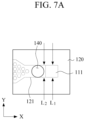
- FIGS. 7A to 7C are diagrams explaining a working principle of a gene amplification chip.
- the cross-section of the first passage 111 may be defined as a value obtained by multiplying a passage width D by a passage length L 1
- the cross-section of the cover channel 121 may be defined as a value obtained by multiplying a channel height h by a channel length L 2 .
- the passage length L 1 and the channel length L 2 may be the same length L in the Y direction.
- FIG. 7B illustrates a state in which a liquid l is injected through the inlet 140 and flows along the cover channel 121 to a boundary between the first non-through hole area 114 and the first passage 111.
- FIG. 7C illustrates a state in which the liquid l is injected through the inlet 140 and flows along the cover channel 121 from the first non-through hole area 114 to an upper side of the first passage 111.
- ⁇ denotes the surface tension of the liquid
- h denotes the channel height of the cover layer
- D denotes the passage width of the chamber layer
- L denotes the channel length of the cover layer or the passage length of the chamber layer
- ⁇ sg denotes the surface tension between a wall surface of the cover layer and air
- ⁇ sl denotes the surface tension between the wall surface of the cover layer and the liquid.
- passage width D of the chamber layer is smaller than the channel height h of the cover layer, ⁇ E is smaller than zero, such that the liquid l passes through the first passage 111 to flow to the bottom channel 131.
- the passage width D of the chamber layer is greater than the channel height h of the cover layer, the flow of the liquid l may be determined by the surface tension ⁇ of the liquid.
- a liquid, having a low surface tension ⁇ such that ⁇ E is a negative number may pass through the first passage 111 to flow to the bottom channel 131.
- a liquid, having a high surface tension ⁇ such that ⁇ E is a positive number may flow only to the cover channel 121 without passing through the first passage 111.
- the sample solution has a surface tension of approximately 70 mN/m
- the oil has a surface tension of approximately 30 mN/m. Accordingly, based on the above principle, if the passage width D is set to a greater value than the channel height h of the cover layer, the sample solution having a higher surface tension may flow only to the cover channel 121 without passing through the first passage 111, and the oil having a lower surface tension may pass through the first passage 111 to flow to the bottom channel 131. For example, if the channel height h of the cover layer is set to approximately 100 ⁇ m, the passage width D of the chamber layer may be set to approximately 700 ⁇ m.
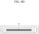
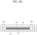
- FIGS. 8A to 8G are diagrams illustrating an example of filling a gene amplification chip with a sample solution and oil.
- a sample solution 10 is injected into the cover channel 121 through the inlet 140. Then, the sample solution 10 is adhered to the first non-through hole area 114, and then flows along the cover channel 121 from the first non-through hole area 114 to the through-hole array 113 without flowing to the first passage 111, so as to be filled in the through holes 112. Then, as illustrated in FIG. 8C , the sample solution 10 flows along the cover channel 121 to be filled in all of the through holes 112. Subsequently, as illustrated in FIG. 8D , a remaining sample solution 10, not filled in the through holes 112, is removed from the second non-through hole area 116 through the outlet 150.
- oil 20 is injected into the cover channel 121 through the inlet 140. Then, some of the oil 20 starts to be filled in the cover channel 121, and a remaining oil 20 flows through the first passage 111 to be filled in the bottom channel 131. Then, as illustrated in FIGS. 8F and 8G , after be filled in the bottom channel 131, the oil 20 flows to the cover channel 121 by passing through the second passage 115, and then joins the oil 20 filled in the cover channel 121 to reach the outlet 150. Then, the outlet 150 and the inlet 140 may be sealed.
- FIGS. 9A to 9D are diagrams illustrating another example of filling a gene amplification chip with a sample solution.
- the sample solution 10 is injected with a volume, corresponding to a total volume of the through holes 112, into the cover channel 121 through the inlet 140. Then, the sample solution 10 may flow from the first non-through hole area 114 to the through-hole array 113 along the cover channel 121 to be sequentially filled in the through holes 112. Subsequently, the oil is filled in the cover channel 121 and the bottom channel 131 through the inlet 140.
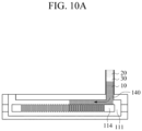
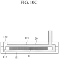
- FIGS. 10A to 10D are diagrams illustrating yet another example of filling a gene amplification chip with a sample solution and oil.
- the sample solution 10, air 30, and the oil 20 are sequentially injected into the cover channel 121 through the inlet 140. Then, the sample solution 10 is adhered to the first non-through hole area 114, and then is pushed by the air 30 and the oil 20 to flow to the through-hole array 113 along the cover channel 121 to be filled in all the through-holes 112. As illustrated in FIG. 10D , the oil 20 continues to flow to the cover channel 121 and the bottom channel 131 to be filled in both the cover channel 121 and the bottom channel 131.
- an outlet 250 may be formed in a bottom layer 230.
- the sample solution may be injected into the cover channel 121 with a volume, corresponding to a total volume of the through holes 112, into the cover channel 121 through the inlet 140, to be filled in all the through holes 112. Then, when the oil is injected into the cover channel 121 through the inlet 140, some of the oil starts to be filled in the cover channel 121, and a remaining oil starts to be filled in the bottom channel 131 by passing through the first passage 111. The oil filled in the cover channel 121 passes through the second passage 115 to flow to the bottom channel 131, and then joins the oil filled in the bottom channel 131 to reach the outlet 250.
- a chamber layer 310 may have the same configuration as the above example, except that the second passage 115 is omitted. If the outlet 150 is formed in the cover layer 120, an additional outlet may be formed in the bottom layer 130.
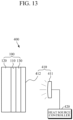
- FIG. 13 is a block diagram illustrating an apparatus for gene amplification according to an embodiment of the present disclosure.
- an apparatus 400 for gene amplification includes the gene amplification chip 100, a heat source 410, and a heat source controller 420.
- the gene amplification chip 100 may have a configuration according to any of above example embodiments.
- the heat source 410 may heat the gene amplification chip 100 so that gene amplification may occur in the sample solution.
- the heat source 410 may include a light source 411 and a photothermal film 412.
- the light source 411 may emit light onto a surface of the photothermal film 412 to heat the sample solution in the chamber layer 110.
- the light source 411 may be any one of a light emitting diode (LED), vertical-cavity surface-emitting laser (VCSEL), a laser diode (LD), a tungsten lamp, a fluorescent lamp, a halogen lamp, a mercury lamp, a xenon lamp, and a metal-halide lamp, or a combination thereof.
- LED light emitting diode
- VCSEL vertical-cavity surface-emitting laser
- LD laser diode
- tungsten lamp tungsten lamp
- fluorescent lamp a fluorescent lamp
- a halogen lamp a mercury lamp
- a xenon lamp a metal-halide lamp
- the photothermal film 412 which is attached to an outer surface of the bottom layer 130, may convert light, emitted by the light source 411, into heat to heat the gene amplification chip 100.
- the light source 411 emits light onto the surface of the photothermal film 412
- the heat converted by the photothermal film 412 may be transferred rapidly to the sample solution, introduced in the chamber layer 110. The heat transfer occurs due to the bottom layer 130 and the chamber layer 110 having high thermal conductivity.
- the photothermal film 412 is attached to the outer surface of the bottom layer 130, such that the light emitted by the light source 411 may be directly absorbed into the photothermal film 412, thereby improving light-to-heat conversion efficiency.
- the photothermal film 412 having a predetermined thickness may be attached to the outer surface of the bottom layer 130.
- the photothermal film 412 may be formed on the outer surface of the bottom layer 130 by patterning or deposition.
- the deposition may include chemical vapor deposition (CVD), physical vapor deposition (PVD), atomic layer deposition (ALD), sputtering, evaporation, etc., but is not limited thereto.
- the photothermal film 412 may be attached to a portion of the outer surface of the bottom layer 130.
- the photothermal film 412 may have a thickness of 500 ⁇ m or less.
- the photothermal film 412 is not limited thereto, and may vary in consideration of heat conductivity and heat retention.
- the photothermal film 412 may be made of a material, such as polymer, metal, metal oxide, nanocomposite, nanostructure, semiconductor, and the like.
- a polyimide (PI) film having a relatively lower thermal conductivity but having a relatively higher heat retention than metal, may be used as the photothermal film 412.
- PI polyimide
- the photothermal film 412 is not limited thereto, and a gold (Au) film or an aluminum nanostructure (AINS) may also be used as the photothermal film 412.
- the heat source controller 420 may control temperature and time of heating by the heat source 410.
- the heat source controller 420 may control the on/off, light intensity, light emission time, light emission period, and the like of the light source 411.
- the light intensity may be controlled by an intensity of an applied current or voltage.
- the controlling of the light emission time may include controlling an emission method such as pulse emission and continuous emission.
- the controlling of the light emission period may include controlling the on/off of the light source.
- the heat source controller 420 controls the light source 411 to heat and cool the photothermal film 412, such that thermal cycling may occur to amplify genes in the chamber layer 110.
- the photothermal film 412 may be cooled by natural convection, and the like.
- FIG. 14 is a block diagram illustrating an apparatus for gene amplification according to another embodiment of the present disclosure.
- an apparatus 500 for gene amplification may further include a temperature sensor 510 and a cooler 520.
- the gene amplification chip 100, the heat source 410, and the heat source controller 420 may have the same configuration as the above embodiments.
- the photothermal film 412 may be attached to the outer surface of the bottom layer 130.
- the temperature sensor 510 may measure temperature of the gene amplification chip 100.
- the temperature sensor 510 may include a thermocouple, an infrared sensor, etc., but is not limited thereto.
- the temperature sensor 510 may be disposed in a thermal pad 530 having high thermal conductivity, to be attached to the photothermal film 412 via the thermal pad 530, and may measure temperature of the photothermal film 412 converted by the light of the light source 411.
- the temperature sensor 510 may be disposed in the thermal pad 530 having high thermal conductivity to be attached to an outer surface of the bottom layer 130, on which the photothermal film 130 is not attached, via the thermal pad 530, and may measure temperature of the bottom layer 130 heated by heat conduction from the photothermal film 412 converted by the light of the light source 411.
- the cooler 520 may cool the photothermal film 412.
- the cooler 520 may include a fan and the like. Based on the temperature measured by the temperature sensor 510, the heat source controller 420 may control the light source 411 according to a temperature profile.
- the temperature profile may be preset through experiments, and may include information, such as temperature over time, holding time, the number of times of repeating cycles, and the like. If the photothermal film 412 may be cooled by natural convection, the cooler 520 may be omitted.
- FIG. 15 is a block diagram illustrating an apparatus for gene amplification including a heat source according to another embodiment of the present disclosure.
- a heat source in an apparatus 600 for gene amplification may include a thermoelement 610.
- the gene amplification chip 100 may have the same configuration as the above embodiments.
- the thermoelement 610 is an element using Peltier effect.
- the Peltier effect is the phenomenon that a potential difference applied across an object causes a temperature difference between both ends of the object as heat is applied along with electrical current. That is, electrical current applied to an object causes a temperature difference, such that one side of the object is heated while the other side thereof is cooled.
- the thermoelement 610 may be attached to the outer surface of the bottom layer 130.
- the heat source controller 620 controls the thermoelement 610 to heat and cool the chamber layer 110, such that thermal cycling may occur to amplify genes in the chamber layer 110.
- the heat source is not limited thereto, and various heat sources may be provided as long as the heat sources may perform the above functions.
- FIG. 16 is a block diagram illustrating an apparatus for bio-particle analysis according to an embodiment of the present disclosure.
- an apparatus 700 for bio-particle analysis may include one or more of the apparatuses 400, 500, and 600 for gene amplification, a detector 710, and a processor 720.
- the apparatuses 400, 500, and 600 for gene amplification may perform gene amplification in a sample solution, and may have the configuration as described in example embodiments.
- the detector 710 may detect a signal generated in response to gene amplification occurring in solution introduced to the chamber layer of the gene amplification apparatus.
- the detector 710 may detect a signal generated in the apparatuses 400, 500, and 600 for gene amplification during or after the gene amplification performed by the apparatuses 400, 500, and 600 for gene amplification.
- the signal may include fluorescence signal, phosphor signal, absorbance signal, surface plasmon resonance signal, Raman signal, and the like.
- the detector 710 may include a photomultiplier tube, a photo detector, a photomultiplier tube array, a photo detector array, a complementary metal-oxide semiconductor (CMOS) image sensor, etc., but is not limited thereto.
- the detector 710 may further include a filter for passing light of a specific wavelength, a mirror for directing the light radiating from the apparatuses 400, 500, and 600 for gene amplification, a lens for collecting light radiating from the apparatuses 400, 500, and 600 for gene amplification, and the like.
- CMOS complementary metal-oxide semiconductor
- the processor 720 may analyze bio-particles based on the detected signal.
- the processor 720 may be electrically connected to the detector 710.
- the processor 720 may detect bio-particles by receiving and analyzing the signal detected by the detector 710.
- the processor 720 may calculate a concentration of the sample solution by measuring the number of through holes 112 in which a fluorescence signal is observed in the apparatuses 400, 500, and 600 for gene amplification.
- the processor 720 may perform quantitative analysis of the bio-particles based on the detected signal using Poisson distribution, Surface-Enhanced Raman Spectroscopy (SERS), and the like based on the detected signal.
- SERS Surface-Enhanced Raman Spectroscopy
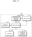
- FIG. 17 is a block diagram illustrating an apparatus for bio-particle analysis according to another embodiment of the present disclosure.
- an apparatus 800 for bio-particle analysis may further include an output interface 810, a storage 820, and a communication interface 830.
- the apparatuses 400, 500, and 600 for gene amplification, the detector 710, and the processor 720 may be configured as described in example embodiments.
- the output interface 810 may output processes or processing results, for example, a bio-particle analysis result of one or more of the apparatuses 400, 500, and 600 for gene amplification, the detector 710, and/or the processor 720.
- the output interface 810 may provide a user with information by visual, audio, and tactile methods and the like using a visual output module (e.g. display), an audio output module (e.g., speaker), a haptic module, and the like.
- the storage 820 may store various data necessary for the apparatuses 400, 500, and 600 for gene amplification, the detector 710, and/or the processor 720, and/or processing results thereof.
- the storage 820 may include at least one storage medium of a flash memory type memory, a hard disk type memory, a multimedia card micro type memory, a card type memory (e.g., an SD memory, an XD memory, etc.), a Random Access Memory (RAM), a Static Random Access Memory (SRAM), a Read Only Memory (ROM), an Electrically Erasable Programmable Read Only Memory (EEPROM), a Programmable Read Only Memory (PROM), a magnetic memory, a magnetic disk, and an optical disk, and the like, but is not limited thereto.
- a flash memory type memory e.g., an SD memory, an XD memory, etc.
- RAM Random Access Memory
- SRAM Static Random Access Memory
- ROM Read Only Memory
- EEPROM Electrically Erasable Programmable Read Only Memory
- PROM
- the communication interface 830 may communicate with an external device to transmit and receive various data necessary for the detector 710 and/or the processor 720, and/or processing results thereof.
- the external device may be medical equipment, a printer to print out results, or a display device.
- the external device may be a digital TV, a desktop computer, a mobile phone, a smartphone, a tablet PC, a laptop computer, Personal Digital Assistants (PDA), Portable Multimedia Player (PMP), a navigation device, an MP3 player, a digital camera, a wearable device, etc., but is not limited thereto.
- the communication interface 830 may communicate with the external device by using communication techniques, such as Bluetooth communication, Bluetooth Low Energy (BLE) communication, Near Field Communication (NFC), WLAN communication, Zigbee communication, Infrared Data Association (IrDA) communication, Wi-Fi Direct (WFD) communication, Ultra-Wideband (UWB) communication, Ant+ communication, WIFI communication, Radio Frequency Identification (RFID) communication, 3G, 4G, and 5G communications, and the like.
- BLE Bluetooth Low Energy
- NFC Near Field Communication
- WLAN Zigbee communication
- IrDA Infrared Data Association
- Wi-Fi Direct (WFD) communication Wi-Fi Direct
- UWB Ultra-Wideband
- Ant+ communication Zigbee communication
- WIFI Radio Frequency Identification
- RFID Radio Frequency Identification
- FIG. 18 is a flowchart illustrating an example of a method of bio-particle analysis.
- a sample solution is injected through the inlet formed in the cover layer of the gene amplification chip in S100.
- a pretreatment process such as heating, chemical treatment, treatment with magnetic beads, solid phase extraction, treatment with ultrasonic waves, etc., may be performed on the sample solution.
- the sample solution is filled in the through holes of the chamber layer of the gene amplification chip
- gene amplification is performed in the chamber layer in S200.
- the sample solution is an RNA sample
- reverse transcription of the RNA sample may be performed by using a reverse transcriptase.
- the enzyme reaction may include, for example, a nucleic acid amplification reaction including at least one of polymerase chain reaction (PCR) amplification and isothermal amplification, a redox reaction, a hydrolytic reaction, and the like.
- the heat source of the apparatus for gene amplification may heat the sample solution in the chamber layer.
- the heat source may perform thermal cycling for heating or cooling the chamber layer, to allow an amplification reaction of the sample solution to occur in the chamber layer of the gene amplification chip.
- the detector of the apparatus for bio-particle analysis may detect a signal generated in response to the gene amplification reaction of the sample solution in the chamber layer of the gene amplification chip in S300.
- the signal may include fluorescence signal, phosphor signal, absorbance signal, surface plasmon resonance signal, Raman signal, and the like.
- the processor of the apparatus for gene amplification may analyze bio-particles based on the detected signal in S400.
- the processor may analyze substance information and a level of amplification of the bio-particles and the like based on the detected signal by using Poisson distribution, Surface-Enhanced Raman Spectroscopy (SERS), and the like.
- SERS Surface-Enhanced Raman Spectroscopy
Landscapes
- Chemical & Material Sciences (AREA)
- Health & Medical Sciences (AREA)
- General Health & Medical Sciences (AREA)
- Chemical Kinetics & Catalysis (AREA)
- Clinical Laboratory Science (AREA)
- Analytical Chemistry (AREA)
- Life Sciences & Earth Sciences (AREA)
- Hematology (AREA)
- Biochemistry (AREA)
- Molecular Biology (AREA)
- Dispersion Chemistry (AREA)
- Organic Chemistry (AREA)
- Immunology (AREA)
- Physics & Mathematics (AREA)
- Engineering & Computer Science (AREA)
- Proteomics, Peptides & Aminoacids (AREA)
- Wood Science & Technology (AREA)
- Zoology (AREA)
- Pathology (AREA)
- General Physics & Mathematics (AREA)
- Nuclear Medicine, Radiotherapy & Molecular Imaging (AREA)
- Bioinformatics & Cheminformatics (AREA)
- Biophysics (AREA)
- Genetics & Genomics (AREA)
- General Engineering & Computer Science (AREA)
- Biotechnology (AREA)
- Microbiology (AREA)
- Apparatus Associated With Microorganisms And Enzymes (AREA)
Applications Claiming Priority (1)
| Application Number | Priority Date | Filing Date | Title |
|---|---|---|---|
| KR1020220116058A KR20240037491A (ko) | 2022-09-15 | 2022-09-15 | 유전자 증폭 칩, 유전자 증폭 장치 및 생체입자 분석 장치 |
Publications (1)
| Publication Number | Publication Date |
|---|---|
| EP4338841A1 true EP4338841A1 (de) | 2024-03-20 |
Family
ID=85251897
Family Applications (1)
| Application Number | Title | Priority Date | Filing Date |
|---|---|---|---|
| EP23156797.5A Pending EP4338841A1 (de) | 2022-09-15 | 2023-02-15 | Genverstärkungschip, vorrichtung zur genverstärkung und vorrichtung zur analyse von biopartikeln |
Country Status (4)
| Country | Link |
|---|---|
| US (1) | US20240091767A1 (de) |
| EP (1) | EP4338841A1 (de) |
| KR (1) | KR20240037491A (de) |
| CN (1) | CN117701374A (de) |
Families Citing this family (1)
| Publication number | Priority date | Publication date | Assignee | Title |
|---|---|---|---|---|
| CN118904409B (zh) * | 2024-06-18 | 2025-06-17 | 哈尔滨桃术生物科技有限公司 | 光热rt-lamp芯片及其制作与检测方法 |
Citations (3)
| Publication number | Priority date | Publication date | Assignee | Title |
|---|---|---|---|---|
| US20090191098A1 (en) * | 2003-09-19 | 2009-07-30 | Life Technologies Corporation | High Density Plate Filler |
| US20100178208A1 (en) * | 2005-10-26 | 2010-07-15 | General Electric Company | Optical sensor array system for parallel processing of chemical and biochemical information |
| EP3142790A1 (de) * | 2014-05-14 | 2017-03-22 | University of Limerick | Mikrofluidische vorrichtung mit kanalplatten |
Family Cites Families (1)
| Publication number | Priority date | Publication date | Assignee | Title |
|---|---|---|---|---|
| EP2972336A4 (de) | 2013-03-15 | 2016-11-16 | Nvs Technologies Inc | Systeme mit analyseinstrumenten |
-
2022
- 2022-09-15 KR KR1020220116058A patent/KR20240037491A/ko active Pending
- 2022-12-15 US US18/082,087 patent/US20240091767A1/en active Pending
-
2023
- 2023-01-10 CN CN202310031416.9A patent/CN117701374A/zh active Pending
- 2023-02-15 EP EP23156797.5A patent/EP4338841A1/de active Pending
Patent Citations (3)
| Publication number | Priority date | Publication date | Assignee | Title |
|---|---|---|---|---|
| US20090191098A1 (en) * | 2003-09-19 | 2009-07-30 | Life Technologies Corporation | High Density Plate Filler |
| US20100178208A1 (en) * | 2005-10-26 | 2010-07-15 | General Electric Company | Optical sensor array system for parallel processing of chemical and biochemical information |
| EP3142790A1 (de) * | 2014-05-14 | 2017-03-22 | University of Limerick | Mikrofluidische vorrichtung mit kanalplatten |
Also Published As
| Publication number | Publication date |
|---|---|
| US20240091767A1 (en) | 2024-03-21 |
| KR20240037491A (ko) | 2024-03-22 |
| CN117701374A (zh) | 2024-03-15 |
Similar Documents
| Publication | Publication Date | Title |
|---|---|---|
| US6537799B2 (en) | Electrical current for controlling fluid parameters in microchannels | |
| US6699713B2 (en) | Polymerase chain reaction system | |
| US11987840B2 (en) | Systems and methods for assessing of biological samples | |
| ES2236739T3 (es) | Dispositivos de manguito a base de silicio para reacciones quimicas. | |
| ES2909055T3 (es) | Métodos y sistemas para el análisis y la cuantificación de ácidos nucleicos | |
| US12220698B2 (en) | Microfluidic chip, and apparatus and method for detecting biomolecules | |
| JP7524061B2 (ja) | サンプルを分析するためのポータブル装置及び方法 | |
| US20070281322A1 (en) | Bioanalytical instrumentation using a light source subsystem | |
| KR20220002071A (ko) | 미세유체 칩, 생체분자 검출 장치 및 방법 | |
| CN101679932A (zh) | 用于热交换化学过程的基于数字微流体的装置 | |
| US20220307068A1 (en) | Gene amplification chip, apparatus for gene amplification, and method of manufacturing gene amplification chip | |
| US20230381772A1 (en) | Gene amplification chip, apparatus for gene amplification, and apparatus for bio-particle analysis | |
| EP4338841A1 (de) | Genverstärkungschip, vorrichtung zur genverstärkung und vorrichtung zur analyse von biopartikeln | |
| WO2009054647A2 (en) | Portable analyzing apparatus based on pcr | |
| JP2023543054A (ja) | 試料処理のためのデバイス及び方法 | |
| JP2010139491A (ja) | 反応液温度測定方法、反応液温度測定装置、反応液温度調整装置及び遺伝子の増幅反応処理を行うための装置 | |
| US20230145041A1 (en) | Apparatus and method for gene amplification | |
| US12005447B2 (en) | Apparatus and method for bio-particle detection | |
| CN111748463A (zh) | 应用于核酸检测的扩增装置和基于扩增装置的检测方法 | |
| CN118483206A (zh) | 一种集成荧光检测模块与温度控制模块的小型数字微流控检测器 | |
| US11648563B2 (en) | Method and system for heating and temperature measurement using patterned thin films | |
| US20230044621A1 (en) | Apparatus and method for gene amplification | |
| EP4397956B1 (de) | Vorrichtung und verfahren zur detektion feiner partikel | |
| KR20230021541A (ko) | 유전자 증폭 장치 및 방법 | |
| US20240288368A1 (en) | Fluorescence detection via light guide |
Legal Events
| Date | Code | Title | Description |
|---|---|---|---|
| PUAI | Public reference made under article 153(3) epc to a published international application that has entered the european phase |
Free format text: ORIGINAL CODE: 0009012 |
|
| STAA | Information on the status of an ep patent application or granted ep patent |
Free format text: STATUS: REQUEST FOR EXAMINATION WAS MADE |
|
| 17P | Request for examination filed |
Effective date: 20240213 |
|
| AK | Designated contracting states |
Kind code of ref document: A1 Designated state(s): AL AT BE BG CH CY CZ DE DK EE ES FI FR GB GR HR HU IE IS IT LI LT LU LV MC ME MK MT NL NO PL PT RO RS SE SI SK SM TR |
|
| P01 | Opt-out of the competence of the unified patent court (upc) registered |
Effective date: 20240530 |
|
| STAA | Information on the status of an ep patent application or granted ep patent |
Free format text: STATUS: EXAMINATION IS IN PROGRESS |
|
| 17Q | First examination report despatched |
Effective date: 20250611 |