EP4338847B1 - Zerstäuberpumpe - Google Patents
Zerstäuberpumpe Download PDFInfo
- Publication number
- EP4338847B1 EP4338847B1 EP23189474.2A EP23189474A EP4338847B1 EP 4338847 B1 EP4338847 B1 EP 4338847B1 EP 23189474 A EP23189474 A EP 23189474A EP 4338847 B1 EP4338847 B1 EP 4338847B1
- Authority
- EP
- European Patent Office
- Prior art keywords
- hole
- liquid
- discharge hole
- press
- liquid discharge
- Prior art date
- Legal status (The legal status is an assumption and is not a legal conclusion. Google has not performed a legal analysis and makes no representation as to the accuracy of the status listed.)
- Active
Links
Images
Classifications
-
- B—PERFORMING OPERATIONS; TRANSPORTING
- B05—SPRAYING OR ATOMISING IN GENERAL; APPLYING FLUENT MATERIALS TO SURFACES, IN GENERAL
- B05B—SPRAYING APPARATUS; ATOMISING APPARATUS; NOZZLES
- B05B11/00—Single-unit hand-held apparatus in which flow of contents is produced by the muscular force of the operator at the moment of use
- B05B11/01—Single-unit hand-held apparatus in which flow of contents is produced by the muscular force of the operator at the moment of use characterised by the means producing the flow
- B05B11/10—Pump arrangements for transferring the contents from the container to a pump chamber by a sucking effect and forcing the contents out through the dispensing nozzle
- B05B11/1001—Piston pumps
-
- B—PERFORMING OPERATIONS; TRANSPORTING
- B05—SPRAYING OR ATOMISING IN GENERAL; APPLYING FLUENT MATERIALS TO SURFACES, IN GENERAL
- B05B—SPRAYING APPARATUS; ATOMISING APPARATUS; NOZZLES
- B05B11/00—Single-unit hand-held apparatus in which flow of contents is produced by the muscular force of the operator at the moment of use
- B05B11/01—Single-unit hand-held apparatus in which flow of contents is produced by the muscular force of the operator at the moment of use characterised by the means producing the flow
- B05B11/10—Pump arrangements for transferring the contents from the container to a pump chamber by a sucking effect and forcing the contents out through the dispensing nozzle
- B05B11/1038—Pressure accumulation pumps, i.e. pumps comprising a pressure accumulation chamber
- B05B11/1039—Pressure accumulation pumps, i.e. pumps comprising a pressure accumulation chamber the outlet valve being mechanically opened after a defined accumulation stroke
-
- B—PERFORMING OPERATIONS; TRANSPORTING
- B05—SPRAYING OR ATOMISING IN GENERAL; APPLYING FLUENT MATERIALS TO SURFACES, IN GENERAL
- B05B—SPRAYING APPARATUS; ATOMISING APPARATUS; NOZZLES
- B05B11/00—Single-unit hand-held apparatus in which flow of contents is produced by the muscular force of the operator at the moment of use
- B05B11/01—Single-unit hand-held apparatus in which flow of contents is produced by the muscular force of the operator at the moment of use characterised by the means producing the flow
- B05B11/10—Pump arrangements for transferring the contents from the container to a pump chamber by a sucking effect and forcing the contents out through the dispensing nozzle
- B05B11/1001—Piston pumps
- B05B11/1023—Piston pumps having an outlet valve opened by deformation or displacement of the piston relative to its actuating stem
- B05B11/1025—Piston pumps having an outlet valve opened by deformation or displacement of the piston relative to its actuating stem a spring urging the outlet valve in its closed position
-
- B—PERFORMING OPERATIONS; TRANSPORTING
- B05—SPRAYING OR ATOMISING IN GENERAL; APPLYING FLUENT MATERIALS TO SURFACES, IN GENERAL
- B05B—SPRAYING APPARATUS; ATOMISING APPARATUS; NOZZLES
- B05B11/00—Single-unit hand-held apparatus in which flow of contents is produced by the muscular force of the operator at the moment of use
- B05B11/01—Single-unit hand-held apparatus in which flow of contents is produced by the muscular force of the operator at the moment of use characterised by the means producing the flow
- B05B11/10—Pump arrangements for transferring the contents from the container to a pump chamber by a sucking effect and forcing the contents out through the dispensing nozzle
- B05B11/1038—Pressure accumulation pumps, i.e. pumps comprising a pressure accumulation chamber
-
- B—PERFORMING OPERATIONS; TRANSPORTING
- B05—SPRAYING OR ATOMISING IN GENERAL; APPLYING FLUENT MATERIALS TO SURFACES, IN GENERAL
- B05B—SPRAYING APPARATUS; ATOMISING APPARATUS; NOZZLES
- B05B11/00—Single-unit hand-held apparatus in which flow of contents is produced by the muscular force of the operator at the moment of use
- B05B11/01—Single-unit hand-held apparatus in which flow of contents is produced by the muscular force of the operator at the moment of use characterised by the means producing the flow
- B05B11/10—Pump arrangements for transferring the contents from the container to a pump chamber by a sucking effect and forcing the contents out through the dispensing nozzle
- B05B11/1042—Components or details
- B05B11/1043—Sealing or attachment arrangements between pump and container
- B05B11/1046—Sealing or attachment arrangements between pump and container the pump chamber being arranged substantially coaxially to the neck of the container
- B05B11/1047—Sealing or attachment arrangements between pump and container the pump chamber being arranged substantially coaxially to the neck of the container the pump being preassembled as an independent unit before being mounted on the container
-
- B—PERFORMING OPERATIONS; TRANSPORTING
- B05—SPRAYING OR ATOMISING IN GENERAL; APPLYING FLUENT MATERIALS TO SURFACES, IN GENERAL
- B05B—SPRAYING APPARATUS; ATOMISING APPARATUS; NOZZLES
- B05B11/00—Single-unit hand-held apparatus in which flow of contents is produced by the muscular force of the operator at the moment of use
- B05B11/01—Single-unit hand-held apparatus in which flow of contents is produced by the muscular force of the operator at the moment of use characterised by the means producing the flow
- B05B11/10—Pump arrangements for transferring the contents from the container to a pump chamber by a sucking effect and forcing the contents out through the dispensing nozzle
- B05B11/1042—Components or details
- B05B11/1061—Pump priming means
-
- B—PERFORMING OPERATIONS; TRANSPORTING
- B05—SPRAYING OR ATOMISING IN GENERAL; APPLYING FLUENT MATERIALS TO SURFACES, IN GENERAL
- B05B—SPRAYING APPARATUS; ATOMISING APPARATUS; NOZZLES
- B05B11/00—Single-unit hand-held apparatus in which flow of contents is produced by the muscular force of the operator at the moment of use
- B05B11/01—Single-unit hand-held apparatus in which flow of contents is produced by the muscular force of the operator at the moment of use characterised by the means producing the flow
- B05B11/10—Pump arrangements for transferring the contents from the container to a pump chamber by a sucking effect and forcing the contents out through the dispensing nozzle
- B05B11/1094—Pump arrangements for transferring the contents from the container to a pump chamber by a sucking effect and forcing the contents out through the dispensing nozzle having inlet or outlet valves not being actuated by pressure or having no inlet or outlet valve
-
- B—PERFORMING OPERATIONS; TRANSPORTING
- B05—SPRAYING OR ATOMISING IN GENERAL; APPLYING FLUENT MATERIALS TO SURFACES, IN GENERAL
- B05B—SPRAYING APPARATUS; ATOMISING APPARATUS; NOZZLES
- B05B11/00—Single-unit hand-held apparatus in which flow of contents is produced by the muscular force of the operator at the moment of use
- B05B11/01—Single-unit hand-held apparatus in which flow of contents is produced by the muscular force of the operator at the moment of use characterised by the means producing the flow
- B05B11/10—Pump arrangements for transferring the contents from the container to a pump chamber by a sucking effect and forcing the contents out through the dispensing nozzle
- B05B11/1042—Components or details
- B05B11/105—Sealing arrangements around pump actuating stem
-
- B—PERFORMING OPERATIONS; TRANSPORTING
- B05—SPRAYING OR ATOMISING IN GENERAL; APPLYING FLUENT MATERIALS TO SURFACES, IN GENERAL
- B05B—SPRAYING APPARATUS; ATOMISING APPARATUS; NOZZLES
- B05B11/00—Single-unit hand-held apparatus in which flow of contents is produced by the muscular force of the operator at the moment of use
- B05B11/01—Single-unit hand-held apparatus in which flow of contents is produced by the muscular force of the operator at the moment of use characterised by the means producing the flow
- B05B11/10—Pump arrangements for transferring the contents from the container to a pump chamber by a sucking effect and forcing the contents out through the dispensing nozzle
- B05B11/1042—Components or details
- B05B11/1052—Actuation means
- B05B11/1053—Actuation means combined with means, other than pressure, for automatically opening a valve during actuation; combined with means for automatically removing closures or covers from the discharge nozzle during actuation
-
- B—PERFORMING OPERATIONS; TRANSPORTING
- B05—SPRAYING OR ATOMISING IN GENERAL; APPLYING FLUENT MATERIALS TO SURFACES, IN GENERAL
- B05B—SPRAYING APPARATUS; ATOMISING APPARATUS; NOZZLES
- B05B11/00—Single-unit hand-held apparatus in which flow of contents is produced by the muscular force of the operator at the moment of use
- B05B11/01—Single-unit hand-held apparatus in which flow of contents is produced by the muscular force of the operator at the moment of use characterised by the means producing the flow
- B05B11/10—Pump arrangements for transferring the contents from the container to a pump chamber by a sucking effect and forcing the contents out through the dispensing nozzle
- B05B11/1042—Components or details
- B05B11/1073—Springs
- B05B11/1074—Springs located outside pump chambers
Definitions
- the present application relates to the field of spray pumps, in particular to a spray pump.
- Spray pumps are widely used in daily life, for example, in shampoos, pesticides and cosmetics, etc.
- a pressure vessel is required. After filling the liquid in the pressure vessel, the inside of the vessel needs to be pressurized, therefore a vessel with a certain strength must be used to withstand the pressure inside the vessel.
- the applicant has filed an application for a pressure accumulation type spray pump.
- spray pump by providing a liquid accumulation cavity, during use, the liquid in the vessel body enters the liquid accumulation cavity and is then sprayed out through the nozzle. Then, when the liquid is not sprayed through the nozzle, the liquid accumulation cavity is in a separate state from the outside, in order to keep the liquid in the liquid accumulation cavity in a pressurized state.
- the liquid in the vessel has not yet entered the liquid accumulation cavity, and a certain amount of air remains in the accumulation cavity. Hence it is necessary to press the pump head with greater force and it is difficult or even hard to press the pump head, which deteriorates the user experience.
- CN 217 349 115 U and US 4 930 999 A are examples of spray pumps of the prior art.
- a spray pump comprising a small piston and an upper pump rod, a small piston and an upper pump rod, wherein a liquid accumulation cavity is formed between the small piston and the upper pump rod, the upper pump rod is provided with a liquid discharge hole which communicates with the liquid accumulation cavity, and the small piston is provided with a sealing column for sealing the liquid discharge hole;
- annular connection portion is disposed at an upper part of the upper pump rod, the liquid discharge hole is located inside the annular connection portion, and the press plate is fixed at an upper part of the annular connection portion.
- the central column comprises a middle annular portion socketed with the liquid discharge hole, the ejector rod is located inside the middle annular portion, and an outer side of the middle annular portion abuts an inner wall of the annular connection portion of the upper pump rod.
- the press plate comprises an upper connection portion connected with the upper pump rod; a through hole is disposed in a central part of the upper connection portion, and the central column passes through the through hole; an annular flange is disposed at an upper part of the upper connection portion, and the annular flange extends to an outside of the upper pump rod.
- an outer diameter of the ejector rod is smaller than an inner diameter of the liquid discharge hole.
- grooves are disposed in the outer side of the ejector rod.
- the spray pump further comprises:
- an upper side of the reset spring abuts a lower side of the annular flange of the press plate, and a lower side of the reset spring abuts the cover plate.
- the central column fixed with the press head moves downward together.
- the central column acts on the small piston to move the small piston down a certain distance, so that the liquid accumulation cavity between the small piston and the upper pump rod is communicated with outside through the liquid discharge hole and the outer liquid discharge hole.
- the air in the liquid accumulation cavity can be discharged, which can avoid the problem that the air in the liquid accumulation cavity cannot be discharged.
- only a small external force is required to press it, which is convenient for the user to press during use.
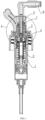
- a spray pump comprises:
- the central column 5 fixed with the press head 6 moves downward together.
- the central column 5 acts on the small piston 3 to move the small piston 3 down a certain distance, so that the liquid accumulation cavity between the small piston 3 and the upper pump rod 4 is communicated with outside through the liquid discharge hole and the outer liquid discharge hole.
- the air in the liquid accumulation cavity can be discharged, which can avoid the problem that the air in the liquid accumulation cavity cannot be discharged.
- only a small external force is required to press it, which is convenient for the user to press during use.
- the liquid accumulation cavity is a liquid storage chamber, and the liquid in the vessel bottle body enters the liquid accumulation cavity through a plurality of structures.
- the space of the liquid accumulation cavity is forced to be reduced, so that the liquid in the liquid accumulation cavity is sprayed out through the liquid discharge hole, having a certain spray effect.
- the spray pump there is air in the liquid accumulation cavity.
- the liquid in the vessel body is difficult to enter the liquid accumulation cavity (if the liquid needs to enter the liquid accumulation cavity, it is necessary to compress the air in the accumulation cavity), or cannot enter the liquid accumulation cavity, which makes it necessary to press the press head 6 with a large force to make the liquid in the vessel body enters the liquid accumulation cavity, and even leads to the inability to press down the press head 6 and cannot be used.
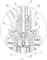
- the press head 6 when the press head 6 is pressed down, under the action of the press head 6, the central column 5 moves down, so that a gap is formed between the small piston 3 and the upper pump rod 4, and the liquid accumulation cavity communicates with the outside through the liquid discharge hole.
- a press gap is disposed between the upper side of the press plate 7 and the lower side of the press head 6, and the height of this press gap is the height of the downward movement of the central column 5 at the beginning. If the sealing column 31 of the small piston 3 extends into the liquid discharge hole, then the press gap is greater than the height of the sealing column 31 extending into the liquid discharge hole, so that the sealing column 31 can be moved to a gap formed with the liquid discharge hole, and the accumulation cavity is communicated with the outside. If the sealing column 31 of the small piston 3 abuts the liquid discharge hole, that is, as long as the small piston 3 is affected and moved down, there will be a gap between the sealing column 31 and the liquid discharge hole, thereby communicating the liquid accumulation cavity with the outside.
- the central column 5 needs to be moved up and down in the position where the upper part of the upper pump rod 4 is located, thus in this embodiment, an annular connection portion 41 is disposed at the upper part of the upper pump rod 4.
- the liquid discharge hole is located inside the annular connection portion 41, and the press plate 7 is fixed at an upper part of the annular connection portion 41.
- the central column 5 is inserted into the annular connection portion 41 of the upper pump rod 4, and the ejector rod 51 on the lower side of the central column 5 is inserted into the liquid hole.
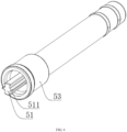
- the central column 5 comprises a middle annular portion 53 socketed with the liquid discharge hole, the ejector rod 51 is located inside the middle annular portion, and an outer side of the middle annular portion 53 abuts an inner wall of the annular connection portion 41 of the upper pump rod 4.
- the press plate 7 serves as a movable transfer structure for transferring the movement of the press head 6 to the upper pump rod 4.
- the press plate 7 comprises an upper connection portion 71 connected with the upper pump rod 4.
- a through hole is disposed in a central part of the upper connection portion 71, and the central column 5 passes through the through hole.
- An annular flange 72 is disposed at an upper part of the upper connection portion 71, and the annular flange 72 extends to the outside of the upper pump rod 4.
- the central column 5 moves up and down at the position of the through hole inside the upper connection portion 71 of the press plate 7, and the press head 6 is disposed at the upper part of the central column 5.
- the press head 6 acts on the annular flange 72 of the press plate 7, thereby pressing down the annular flange 72 and the upper pump rod 4 fixed with the annular flange 72 (press plate 7).
- the ejector rod 51 is in the liquid discharge hole, and at the same time the ejector rod 51 acts on the sealing column 31 of the small piston 3, so that the liquid accumulation cavity is communicated with the liquid discharge hole, thereby the air and liquid in the liquid accumulation cavity can pass through the liquid discharge hole, the central hole 52, and the outer liquid discharge hole, and then be sprayed out.
- the ejector rod 51 is in the liquid discharge hole, so in order not to affect the flow of air and liquid, the outer diameter of the ejector rod 51 is smaller than the inner diameter of the liquid discharge hole, thereby forming a flow gap to ensure the normal flow of air and liquid.
- the ejector rod 51 is provided with grooves 511 on the outside.
- the gap between the ejector rod 51 and the inner wall of the liquid discharge hole can be increased, thereby increasing the flow speed of air and liquid.
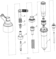
- the spray pump further comprises a main body 1 having a hollow portion, an upper through hole and a lower through hole are disposed at the two ends of the hollow portion of the main body 1; a cover plate 2 fixed with the main body 1, which seals the hollow portion of the main body 1 from the outside at the upper through hole, and the cover plate 2 is provided with a through hole for the annular connection portion 41 of the upper pump rod 4 to pass through; and a reset spring 8 located between the cover plate 2 and the press plate 7.
- an upper side of the reset spring 8 abuts a lower side of the annular flange 72 of the press plate 7, and a lower side of the reset spring 8 abuts the cover plate2.
- the reset spring 8 is located between the cover plate 2 and the annular flange 72 of the press plate 7.
- the press head 6 is pressed down, and the press plate 7 is moved down, thereby compressing the reset spring 8.
- the press plate 7, the upper pump rod 4 fixed with the press plate 7, and the pressure head 6 on the upper part of the press plate 7 are all moved up, so that the press plate 7, the upper pump rod 4, and the press head 6 are restored to their original positions.
Landscapes
- Reciprocating Pumps (AREA)
- Containers And Packaging Bodies Having A Special Means To Remove Contents (AREA)
- Closures For Containers (AREA)
Claims (8)
- Zerstäuberpumpe, umfassend:einen kleinen Kolben (3) und eine obere Pumpenstange (4),wobei eine Flüssigkeitsansammlungskavität zwischen dem kleinen Kolben (3) und der oberen Pumpenstange (4) gebildet wird,die obere Pumpenstange mit einer Flüssigkeitsablauföffnung versehen ist, die mit der Flüssigkeitsansammlungskavität in Verbindung steht, und der kleine Kolben mit einer Dichtungssäule (31) zum Abdichten der Flüssigkeitsablauföffnung versehen ist;eine zentrale Säule (5) mit einer Auswerferstange (51), die an einem unteren Teil der zentralen Säule (5) vorgesehen ist und bis in die Flüssigkeitsablauföffnung reicht, wobei ein Flüssigkeitsstromspalt zwischen der Auswerferstange (51) und der Flüssigkeitsablauföffnung angeordnet und eine zentrale Öffnung (52), die mit der Flüssigkeitsablauföffnung in Verbindung steht, an einem zentralen Teil der zentralen Säule angeordnet ist;einen Druckkopf (6), der mit der zentralen Säule (5) an einem unteren Teil des Druckkopfes befestigt ist, wobei eine äußere Flüssigkeitsablauföffnung, die mit der zentralen Öffnung (52) verbunden ist, an einem zentralen Teil des Druckkopfes angeordnet ist:
undeine Druckplatte (7), die mit der oberen Pumpenstange (4) befestigt ist,wobei ein Druckspalt zwischen einer Oberseite der Druckplatte (7) und einer Unterseite des Druckkopfes (6) angeordnet ist;wobei sich, wenn sich der Druckkopf (6) nach unten bewegt, die zentrale Säule (5) synchronmit dem Druckkopf (6) nach unten bewegt und die Auswerferstange (51) der zentralen Säule (5) den kleinen Kolben (3) nach unten schiebt,wobei der kleine Kolben (3) mit der oberen Pumpenstange (4) in Verbindung steht,und die Flüssigkeitsansammlungskavität mit der Außenumgebung in Verbindung steht. - Zerstäuberpumpe nach Anspruch 1, wobei ein ringförmiger Verbindungsabschnitt (41) an einem oberen Teil der oberen Pumpenstange (4) angeordnet ist,
die Flüssigkeitsablauföffnung sich im Inneren des ringförmigen Verbindungsabschnitts befindet und die Druckplatte (7) an einem oberen Teil des ringförmigen Verbindungsabschnitts (41) befestigt ist. - Zerstäuberpumpe nach Anspruch 2, wobei die zentrale Säule (5)einen mittleren ringförmigen Abschnitt (53) umfasst, der mit der Flüssigkeitsablauföffnung zusammengesteckt ist, und die Auswerferstange (51) im Inneren des mittleren ringförmigen Abschnitts (53) untergebracht ist,und eine Außenseite des mittleren ringförmigen Abschnitts an eine Innenwand des ringförmigen Verbindungsabschnitts (41) der oberen Pumpenstange (4) angrenzt.
- Zerstäuberpumpe nach Anspruch 2 oder 3, wobei die Druckplatte (7) einen oberen Verbindungsabschnitt (71) umfasst, der mit der oberen Pumpenstange (4) verbunden ist;eine Durchgangsöffnung in einem zentralen Teil des oberen Verbindungsabschnitts angeordnet ist und die zentrale Säule (5) durch die Durchgangsöffnung verläuft; ein ringförmiger Flansch (72) an einem oberen Teil des oberen Verbindungsabschnitts (71) angeordnet ist,und der ringförmige Flansch (72) zu einer Außenseite der oberen Pumpenstange (4) verläuft.
- Zerstäuberpumpe nach Anspruch 4, wobei ein Außendurchmesser der Auswerferstange (51) kleiner ist als ein Innendurchmesser der Flüssigkeitsablauföffnung.
- Zerstäuberpumpe nach Anspruch 4, wobei Nuten (511) in der Außenseite der Auswerferstange (51) angeordnet sind.
- Zerstäuberpumpe nach Anspruch 4, wobei die Zerstäuberpumpe außerdem Folgendes umfasst:einen Hauptkörper (1),der einen hohlen Abschnitt aufweist, wobei eine obere Durchgangsöffnung und eine untere Durchgangsöffnung jeweils an zwei Enden des hohlen Abschnitts des Hauptkörpers angeordnet sind;eine Abdeckplatte (2), die mit dem Hauptkörper befestigt ist, die den hohlen Abschnitt des Hauptkörpers von der Außenseite an der oberen Durchgangsöffnung abdichtet und mit einer Durchgangsöffnung für den Durchgang des ringförmigen Verbindungsabschnitts der oberen Pumpenstange versehen ist; und eine Rückstellfeder (8), die zwischen der Abdeckplatte (2) und der Druckplatte (7) angeordnet ist.
- Zerstäuberpumpe nach Anspruch 7, wobei eine Oberseite der Rückstellfeder (8) an eine Unterseite des ringförmigen Flansches (72) der Druckplatte (7) angrenzt,
und eine Unterseite der Rückstellfeder an die Abdeckplatte (2) angrenzt.
Applications Claiming Priority (1)
| Application Number | Priority Date | Filing Date | Title |
|---|---|---|---|
| CN202222417761.XU CN218056508U (zh) | 2022-09-13 | 2022-09-13 | 一种喷雾泵 |
Publications (3)
| Publication Number | Publication Date |
|---|---|
| EP4338847A1 EP4338847A1 (de) | 2024-03-20 |
| EP4338847C0 EP4338847C0 (de) | 2025-01-01 |
| EP4338847B1 true EP4338847B1 (de) | 2025-01-01 |
Family
ID=84408093
Family Applications (1)
| Application Number | Title | Priority Date | Filing Date |
|---|---|---|---|
| EP23189474.2A Active EP4338847B1 (de) | 2022-09-13 | 2023-08-03 | Zerstäuberpumpe |
Country Status (6)
| Country | Link |
|---|---|
| US (1) | US12343744B2 (de) |
| EP (1) | EP4338847B1 (de) |
| KR (1) | KR200499922Y1 (de) |
| CN (1) | CN218056508U (de) |
| AU (1) | AU2023208218B2 (de) |
| GB (1) | GB2622935B (de) |
Families Citing this family (1)
| Publication number | Priority date | Publication date | Assignee | Title |
|---|---|---|---|---|
| CN117602234B (zh) * | 2023-12-19 | 2026-03-13 | 万通(苏州)定量阀系统有限公司 | 一种料体分配装置 |
Family Cites Families (16)
| Publication number | Priority date | Publication date | Assignee | Title |
|---|---|---|---|---|
| US4325499A (en) * | 1980-10-31 | 1982-04-20 | Ethyl Products Company | Extended spray pump |
| EP0345132B1 (de) * | 1988-06-02 | 1993-09-22 | Societe Technique De Pulverisation Step | Vordruck Dosierpumpe mit verbessertem Ansaugverhalten |
| DE3911510A1 (de) * | 1989-04-08 | 1990-10-11 | Pfeiffer Erich Gmbh & Co Kg | Austragvorrichtung fuer medien |
| FR2656900B1 (fr) * | 1990-01-10 | 1994-01-28 | Oreal | Pompe manuelle a precompression pour la pulverisation d'un liquide, notamment d'un parfum. |
| GB2245936A (en) * | 1990-05-01 | 1992-01-15 | Bespak Plc | Dispencing device |
| US5217148A (en) * | 1991-02-11 | 1993-06-08 | Spruhventile Gmbh | Pharmaceutical pump dispenser |
| US5503306A (en) * | 1994-10-19 | 1996-04-02 | Aptar Group, Inc. | Manually actuated pump |
| US6170713B1 (en) * | 1998-10-28 | 2001-01-09 | Emson, Inc. | Double spring precompression pump with priming feature |
| FR2815674B1 (fr) * | 2000-10-23 | 2003-05-02 | Valois Sa | Pompe de distribution de produit fluide |
| DE10220557A1 (de) * | 2002-05-02 | 2003-11-13 | Pfeiffer Erich Gmbh & Co Kg | Spender zum Austrag fließfähiger Medien |
| FR2906232B1 (fr) * | 2006-09-27 | 2008-12-12 | Valois Sas | Dispositif de distribution de produit fluide. |
| CN102991839B (zh) * | 2011-09-08 | 2016-04-20 | 丁要武 | 使用弹性体活塞的液体泵、活塞组件及其生产方法 |
| KR101355655B1 (ko) * | 2012-06-21 | 2014-01-29 | 정만택 | 잔존물 제거를 위한 공기분출형 화장품 용기 |
| FR3002293B1 (fr) * | 2013-02-15 | 2015-04-10 | Aptar France Sas | Pompe a precompression amelioree. |
| KR101951627B1 (ko) * | 2018-09-20 | 2019-02-25 | (주)삼화피앤티 | 스프레이 펌프 |
| CN217349115U (zh) * | 2022-04-29 | 2022-09-02 | 广东尼特包装制品有限公司 | 储压式喷雾泵、喷雾装置 |
-
2022
- 2022-09-13 CN CN202222417761.XU patent/CN218056508U/zh active Active
-
2023
- 2023-04-13 US US18/300,347 patent/US12343744B2/en active Active
- 2023-07-28 KR KR2020230001585U patent/KR200499922Y1/ko active Active
- 2023-07-29 AU AU2023208218A patent/AU2023208218B2/en active Active
- 2023-08-01 GB GB2311844.1A patent/GB2622935B/en active Active
- 2023-08-03 EP EP23189474.2A patent/EP4338847B1/de active Active
Also Published As
| Publication number | Publication date |
|---|---|
| GB2622935A (en) | 2024-04-03 |
| US20230347367A1 (en) | 2023-11-02 |
| US12343744B2 (en) | 2025-07-01 |
| GB2622935B (en) | 2025-09-24 |
| CN218056508U (zh) | 2022-12-16 |
| EP4338847A1 (de) | 2024-03-20 |
| KR20240000512U (ko) | 2024-03-20 |
| AU2023208218B2 (en) | 2024-08-01 |
| KR200499922Y1 (ko) | 2026-01-06 |
| EP4338847C0 (de) | 2025-01-01 |
| AU2023208218A1 (en) | 2024-03-28 |
| GB202311844D0 (en) | 2023-09-13 |
Similar Documents
| Publication | Publication Date | Title |
|---|---|---|
| US5092495A (en) | Precompression pump for spray discharge of a liquid | |
| US12098713B2 (en) | Vacuum pump | |
| FI90739C (fi) | Kuristamaton poistopumppukokoonpano | |
| US6722585B1 (en) | Fluid spray head including a closure member | |
| EP1510259B1 (de) | Sprühpumpe | |
| EP4338847A1 (de) | Zerstäuberpumpe | |
| US7029249B2 (en) | Electronic micro-pump | |
| US20240109715A1 (en) | Pressure storage type spray pump and pressure storage type spray device | |
| CN217349115U (zh) | 储压式喷雾泵、喷雾装置 | |
| JP4038344B2 (ja) | 蓄圧式液体噴出器 | |
| KR102496965B1 (ko) | 펌프 조립체 | |
| JP2007515285A (ja) | 流体ディスペンサ部材 | |
| EP2886003B1 (de) | Düsenstruktur für einen Spenderpumpenknopf | |
| KR100782330B1 (ko) | 용기 출몰식 펌프디스펜서 | |
| CN222267512U (zh) | 按压式喷射泵及容器 | |
| CN114364615A (zh) | 高压预压缩泵 | |
| EP1315575B1 (de) | Fingerbetätigte zerstäubuurgspumpe zum austrag von bestimmten medieumengen | |
| CN224127560U (zh) | 一种剂量可调的按压喷头 | |
| KR20220120169A (ko) | 자바라 구조의 펌프가 구비된 화장액 용기 | |
| EP0493643B1 (de) | Zerstäuber | |
| CN222678428U (zh) | 一种喷雾器 | |
| KR102677847B1 (ko) | 압축공기에 의해 내용물을 분사하는 양방향 스프레이 용기 | |
| US20050023299A1 (en) | Finger-Operated spray pump ejaculating fluid in fixed quantity | |
| KR102111972B1 (ko) | 역립상태에서도 화장액이 분사되는 화장액 용기 | |
| CN119137047A (zh) | 泵及喷出容器 |
Legal Events
| Date | Code | Title | Description |
|---|---|---|---|
| PUAI | Public reference made under article 153(3) epc to a published international application that has entered the european phase |
Free format text: ORIGINAL CODE: 0009012 |
|
| STAA | Information on the status of an ep patent application or granted ep patent |
Free format text: STATUS: THE APPLICATION HAS BEEN PUBLISHED |
|
| AK | Designated contracting states |
Kind code of ref document: A1 Designated state(s): AL AT BE BG CH CY CZ DE DK EE ES FI FR GB GR HR HU IE IS IT LI LT LU LV MC ME MK MT NL NO PL PT RO RS SE SI SK SM TR |
|
| STAA | Information on the status of an ep patent application or granted ep patent |
Free format text: STATUS: REQUEST FOR EXAMINATION WAS MADE |
|
| 17P | Request for examination filed |
Effective date: 20240328 |
|
| RBV | Designated contracting states (corrected) |
Designated state(s): AL AT BE BG CH CY CZ DE DK EE ES FI FR GB GR HR HU IE IS IT LI LT LU LV MC ME MK MT NL NO PL PT RO RS SE SI SK SM TR |
|
| GRAP | Despatch of communication of intention to grant a patent |
Free format text: ORIGINAL CODE: EPIDOSNIGR1 |
|
| STAA | Information on the status of an ep patent application or granted ep patent |
Free format text: STATUS: GRANT OF PATENT IS INTENDED |
|
| INTG | Intention to grant announced |
Effective date: 20240820 |
|
| RIN1 | Information on inventor provided before grant (corrected) |
Inventor name: ZENG, ZHIYUN Inventor name: MEI, YUANHONG |
|
| GRAS | Grant fee paid |
Free format text: ORIGINAL CODE: EPIDOSNIGR3 |
|
| GRAA | (expected) grant |
Free format text: ORIGINAL CODE: 0009210 |
|
| STAA | Information on the status of an ep patent application or granted ep patent |
Free format text: STATUS: THE PATENT HAS BEEN GRANTED |
|
| AK | Designated contracting states |
Kind code of ref document: B1 Designated state(s): AL AT BE BG CH CY CZ DE DK EE ES FI FR GB GR HR HU IE IS IT LI LT LU LV MC ME MK MT NL NO PL PT RO RS SE SI SK SM TR |
|
| REG | Reference to a national code |
Ref country code: GB Ref legal event code: FG4D |
|
| REG | Reference to a national code |
Ref country code: CH Ref legal event code: EP |
|
| REG | Reference to a national code |
Ref country code: DE Ref legal event code: R096 Ref document number: 602023001580 Country of ref document: DE |
|
| REG | Reference to a national code |
Ref country code: IE Ref legal event code: FG4D |
|
| U01 | Request for unitary effect filed |
Effective date: 20250122 |
|
| U07 | Unitary effect registered |
Designated state(s): AT BE BG DE DK EE FI FR IT LT LU LV MT NL PT RO SE SI Effective date: 20250129 |
|
| PG25 | Lapsed in a contracting state [announced via postgrant information from national office to epo] |
Ref country code: PL Free format text: LAPSE BECAUSE OF FAILURE TO SUBMIT A TRANSLATION OF THE DESCRIPTION OR TO PAY THE FEE WITHIN THE PRESCRIBED TIME-LIMIT Effective date: 20250101 |
|
| PG25 | Lapsed in a contracting state [announced via postgrant information from national office to epo] |
Ref country code: ES Free format text: LAPSE BECAUSE OF FAILURE TO SUBMIT A TRANSLATION OF THE DESCRIPTION OR TO PAY THE FEE WITHIN THE PRESCRIBED TIME-LIMIT Effective date: 20250101 |
|
| PG25 | Lapsed in a contracting state [announced via postgrant information from national office to epo] |
Ref country code: IS Free format text: LAPSE BECAUSE OF FAILURE TO SUBMIT A TRANSLATION OF THE DESCRIPTION OR TO PAY THE FEE WITHIN THE PRESCRIBED TIME-LIMIT Effective date: 20250501 Ref country code: NO Free format text: LAPSE BECAUSE OF FAILURE TO SUBMIT A TRANSLATION OF THE DESCRIPTION OR TO PAY THE FEE WITHIN THE PRESCRIBED TIME-LIMIT Effective date: 20250401 |
|
| PG25 | Lapsed in a contracting state [announced via postgrant information from national office to epo] |
Ref country code: HR Free format text: LAPSE BECAUSE OF FAILURE TO SUBMIT A TRANSLATION OF THE DESCRIPTION OR TO PAY THE FEE WITHIN THE PRESCRIBED TIME-LIMIT Effective date: 20250101 |
|
| U20 | Renewal fee for the european patent with unitary effect paid |
Year of fee payment: 3 Effective date: 20250609 |
|
| PG25 | Lapsed in a contracting state [announced via postgrant information from national office to epo] |
Ref country code: GR Free format text: LAPSE BECAUSE OF FAILURE TO SUBMIT A TRANSLATION OF THE DESCRIPTION OR TO PAY THE FEE WITHIN THE PRESCRIBED TIME-LIMIT Effective date: 20250402 |
|
| PG25 | Lapsed in a contracting state [announced via postgrant information from national office to epo] |
Ref country code: CZ Free format text: LAPSE BECAUSE OF FAILURE TO SUBMIT A TRANSLATION OF THE DESCRIPTION OR TO PAY THE FEE WITHIN THE PRESCRIBED TIME-LIMIT Effective date: 20250101 |
|
| PG25 | Lapsed in a contracting state [announced via postgrant information from national office to epo] |
Ref country code: SM Free format text: LAPSE BECAUSE OF FAILURE TO SUBMIT A TRANSLATION OF THE DESCRIPTION OR TO PAY THE FEE WITHIN THE PRESCRIBED TIME-LIMIT Effective date: 20250101 |
|
| PG25 | Lapsed in a contracting state [announced via postgrant information from national office to epo] |
Ref country code: SK Free format text: LAPSE BECAUSE OF FAILURE TO SUBMIT A TRANSLATION OF THE DESCRIPTION OR TO PAY THE FEE WITHIN THE PRESCRIBED TIME-LIMIT Effective date: 20250101 |
|
| PLBE | No opposition filed within time limit |
Free format text: ORIGINAL CODE: 0009261 |
|
| STAA | Information on the status of an ep patent application or granted ep patent |
Free format text: STATUS: NO OPPOSITION FILED WITHIN TIME LIMIT |
|
| 26N | No opposition filed |
Effective date: 20251002 |
|
| PG25 | Lapsed in a contracting state [announced via postgrant information from national office to epo] |
Ref country code: MC Free format text: LAPSE BECAUSE OF FAILURE TO SUBMIT A TRANSLATION OF THE DESCRIPTION OR TO PAY THE FEE WITHIN THE PRESCRIBED TIME-LIMIT Effective date: 20250101 |