EP4338885A1 - Machine-outil avec collecteur de poussière et collecteur de poussière - Google Patents
Machine-outil avec collecteur de poussière et collecteur de poussière Download PDFInfo
- Publication number
- EP4338885A1 EP4338885A1 EP22195277.3A EP22195277A EP4338885A1 EP 4338885 A1 EP4338885 A1 EP 4338885A1 EP 22195277 A EP22195277 A EP 22195277A EP 4338885 A1 EP4338885 A1 EP 4338885A1
- Authority
- EP
- European Patent Office
- Prior art keywords
- collection box
- dust collection
- machine tool
- dust
- filter
- Prior art date
- Legal status (The legal status is an assumption and is not a legal conclusion. Google has not performed a legal analysis and makes no representation as to the accuracy of the status listed.)
- Withdrawn
Links
Images




Classifications
-
- B—PERFORMING OPERATIONS; TRANSPORTING
- B23—MACHINE TOOLS; METAL-WORKING NOT OTHERWISE PROVIDED FOR
- B23Q—DETAILS, COMPONENTS, OR ACCESSORIES FOR MACHINE TOOLS, e.g. ARRANGEMENTS FOR COPYING OR CONTROLLING; MACHINE TOOLS IN GENERAL CHARACTERISED BY THE CONSTRUCTION OF PARTICULAR DETAILS OR COMPONENTS; COMBINATIONS OR ASSOCIATIONS OF METAL-WORKING MACHINES, NOT DIRECTED TO A PARTICULAR RESULT
- B23Q11/00—Accessories fitted to machine tools for keeping tools or parts of the machine in good working condition or for cooling work; Safety devices specially combined with or arranged in, or specially adapted for use in connection with, machine tools
- B23Q11/0042—Devices for removing chips
- B23Q11/0046—Devices for removing chips by sucking
-
- B—PERFORMING OPERATIONS; TRANSPORTING
- B23—MACHINE TOOLS; METAL-WORKING NOT OTHERWISE PROVIDED FOR
- B23Q—DETAILS, COMPONENTS, OR ACCESSORIES FOR MACHINE TOOLS, e.g. ARRANGEMENTS FOR COPYING OR CONTROLLING; MACHINE TOOLS IN GENERAL CHARACTERISED BY THE CONSTRUCTION OF PARTICULAR DETAILS OR COMPONENTS; COMBINATIONS OR ASSOCIATIONS OF METAL-WORKING MACHINES, NOT DIRECTED TO A PARTICULAR RESULT
- B23Q11/00—Accessories fitted to machine tools for keeping tools or parts of the machine in good working condition or for cooling work; Safety devices specially combined with or arranged in, or specially adapted for use in connection with, machine tools
- B23Q11/0042—Devices for removing chips
- B23Q11/0071—Devices for removing chips dust collectors for hand tools
-
- B—PERFORMING OPERATIONS; TRANSPORTING
- B25—HAND TOOLS; PORTABLE POWER-DRIVEN TOOLS; MANIPULATORS
- B25D—PERCUSSIVE TOOLS
- B25D17/00—Details of, or accessories for, portable power-driven percussive tools
-
- B—PERFORMING OPERATIONS; TRANSPORTING
- B25—HAND TOOLS; PORTABLE POWER-DRIVEN TOOLS; MANIPULATORS
- B25D—PERCUSSIVE TOOLS
- B25D17/00—Details of, or accessories for, portable power-driven percussive tools
- B25D17/20—Devices for cleaning or cooling tool or work
Definitions
- the present invention relates to a machine tool that can be connected to an elongated tool that extends forward in a spatial direction, the machine tool being set up to drive the tool to a rotating and/or striking movement.
- the machine tool includes a dust collection box for extracting dust-laden air from a work area of the machine tool, wherein the dust can be filtered out of the dust-laden air using a filter.
- a virtual center plane can be placed through a main body of the machine tool and/or the dust collection box, with the virtual center plane dividing the main body into two halves, with an inlet of the dust collection box for the dust-laden air predominantly on one side and the filter of the dust collection box predominantly on the other Side of the middle plane is arranged.
- the invention relates to a dust collection box for a machine tool, wherein the inlet and the filter of the dust collection box are on different sides, i.e. in different halves of the rod collection box.
- dust collection boxes are known which can be connected to the machine tool in order to extract dust-laden air from a working area of the machine tool.
- Machine tools can be connected to tools that can be used to carry out work.
- the hammer drill can be connected to an elongated tool which can be driven by the device into a rotating and/or a striking movement.
- so-called "onboard" dust collection boxes for machine tools there are mainly two different types of dust collection boxes known: On the one hand, dust collection boxes are known in which the suction channel between the work area and the dust collection box is guided along the tool on one side of the tool of the machine tool.
- dust collection boxes are known in which the suction channel is guided in or near a plane, the plane containing a working axis and a grip axis of the machine tool. This level is therefore preferably also referred to as the “working plane” of the machine tool.
- the working axis corresponds to the axis in which the tool of the machine tool lies, the handle axis containing the main handle of the machine tool.
- the dust collection boxes with the lateral guidance of the suction channel often have good suction performance, but are often very large and unwieldy, so that the machine tool, when connected to such a dust collection box, also becomes very large and unwieldy. This can make handling the machine tool more difficult and make working with the machine tool less comfortable and laborious.
- the filter for filtering out the dust from the dust-laden air is often located on a front or rear wall of the dust collection box. This can disadvantageously cause dust to collect on the filter when the machine tool is being used on a surface such as a floor or ceiling, i.e. overhead. In this way, the filter can quickly become clogged, so that, for example, only a small number of drill holes can be created with the machine tool before the filter has to be replaced or cleaned.
- the object on which the present invention is based is to overcome the shortcomings and disadvantages of the prior art described above and to provide a machine tool that combines the advantages of the known designs.
- the dust collection box to be provided should be particularly compact and handy in order to be able to provide a handy and comfortable machine tool.
- Experts would welcome it if a cost-effective and easy-to-replace filter could be provided for the dust collection box and if the dust collection box could be designed to be particularly tight in order to optimally utilize the existing suction power and not have any leaks.
- a machine tool which can be connected to an elongated tool which extends forward in a spatial direction.
- the machine tool is set up to drive the tool to a rotating and/or striking movement.
- the machine tool comprises a dust collection box and can be releasably connected to it, the dust collection box being designed to extract dust-laden air from a working area of the machine tool and to filter out the dust from the dust-laden air by means of a filter, so that the dust in an interior of the dust collection box up to can be collected during emptying.
- a virtual center plane can be placed through a main body of the machine tool and/or the dust collection box, wherein the virtual center plane is set up to divide the main body into a first side and a second side in a sectional view looking from a front spatial direction.
- An inlet of the dust collection box for the dust-laden air is arranged predominantly on one side of the central plane, while the filter of the dust collection box is predominantly arranged on the other side of the central plane.
- the first side of the main body of the machine tool and/or the dust collection box can be referred to as the left side, while the second side of the main body of the machine tool and/or the dust collection box can be referred to as the right side.
- the main body of the machine tool and/or the dust collection box is preferably viewed from a front spatial direction, the front spatial direction preferably being determined by the position of the tool of the machine tool, while the main body of the machine tool preferably defines the rear area of the machine tool and the rear spatial direction .
- the main body can be a main body of the machine tool, which includes, for example, the motor, the impact mechanism and/or the battery of the machine tool.
- the main body is a main body of the dust collection box.
- the virtual center plane mentally divides the main body of the machine tool or the dust collection box into two sides or halves.
- a larger part of the inlet of the dust collection box is arranged on one side of the machine tool or its main body, while a smaller part of the inlet of the dust collection box is arranged on the other side of the machine tool or its main body is.
- the larger part can of the inlet of the dust collection box in the sense of the invention can be referred to as “the predominant part of the inlet of the dust collection box.
- the larger part i.e. the majority of the filter
- the smaller part of the filter is arranged on the other side of the machine tool or its main body is, with the major portions of the inlet and filter being located on opposite sides of the main body of the machine tool.
- the formulation that a “predominant” part of an object lies on one side of the machine tool or the dust collection box preferably means in the sense of the invention that the object lies entirely or partially, and if partially, with the larger of the at least two parts, on one side side or half of the machine tool or the dust collection box.
- the wording of the majority includes that the object is completely arranged on one side or half of the machine tool or the dust collection box.
- this preferably means that the larger part of the inlet and the smaller part of the filter are arranged on one side of the main body of the machine tool and / or the dust collection box, while the larger part of the filter and the smaller part of the inlet are on the other, i.e. opposite side of the main body of the machine tool and / or the dust collection box are arranged.
- the separation into the two halves of the main body takes place through the virtual center plane of the machine tool and/or the dust collection box, which can preferably coincide with the previously described working plane of the machine tool.
- the virtual center plane of the machine tool cuts the handle of the machine tool and, if the machine tool is a battery-operated machine tool, the battery of the machine tool and essentially divides it in the middle into two similar or symmetrical halves.
- the handle of the machine tool can preferably be a so-called D-handle, which can be grasped by a user of the machine tool in order to grasp the machine tool and guide it when working with it.
- This Advantage of the machine tool can be achieved in particular in all three main applications of the machine tool (working on the floor, on the wall and overhead on the ceiling), because in none of the three main applications is the filter covered by dust, so that it quickly becomes clogged or blocked becomes. Due to the arrangement and design of the dust collection box, the dust advantageously falls next to the filter in the main applications, so that the invention avoids “flooding” or “sugaring” of the filter.
- a further advantage of the invention is that the invention can be used to provide a particularly compact and handy dust collection box.
- the dust-laden air can first flow or be sucked from the inlet of the dust collection box into the interior of the dust collection box, where part of the dust separates from the air flow and lies on the bottom of the dust collection box.
- the air continues to flow through the filter, with the dust collection box comprising a suction unit to generate the air flow, through which the air flow flows last in the proposed arrangement of the dust collection box in the machine tool.
- the air flow is already essentially dust-free because the dust has either settled inside the dust collection box or the dust has been filtered out of the air flow by the filter.
- particularly good suction performance can be achieved with the proposed arrangement of the dust collection box within the machine tool.
- the proposed arrangement of the dust collection box on the machine tool is referred to as “asymmetrical” within the meaning of the invention.
- the dust collection box of the proposed machine tool is preferably referred to as an “asymmetric dust collection box” in the sense of the invention, the asymmetrical arrangement of the components of the dust collection box being characterized in that the inlet of the dust collection box is predominantly on one side of the main body of the machine tool and / or the dust collection box is arranged, while the filter of the dust collection box is arranged predominantly on the other or opposite side of the main body of the machine tool and / or the dust collection box.
- the asymmetrical arrangement of the dust collection box ensures in particular that the filter of the dust collection box is not covered by dust in any of the three main applications of the machine tool (working on the floor, on the wall and overhead on the ceiling).
- the dust-laden air can be guided from the work area through a suction channel to the inlet of the dust collection box, with the virtual central plane running through the suction channel.
- the suction channel is located in the middle of the machine tool or in the dust collection box, which is expressed by the fact that the virtual center plane cuts the suction channel and mentally divides it into two essentially symmetrical halves.
- the suction channel is designed to be telescopic.
- the suction channel can advantageously be adapted to different lengths of the tool of the machine tool or to different desired depths of the borehole.
- the machine tool has a first seal, the first seal being designed to guide the dust-laden air into the dust collection box.
- This first seal is preferably present in the area of the inlet of the dust collection box.
- the dust collection box has a second seal, the second seal being designed to direct the cleaned air from the filter to a suction unit of the dust collection box.
- the second seal is preferably present in an upper region of the dust collection box.
- the machine tool has a first seal for conducting the dust-laden air into the dust collection box and a second seal for conducting the cleaned air from the filter to a suction unit of the dust collection box, the first seal and the second seal being in are oriented in essentially the same spatial direction.
- this preferably means that the first and second seals are essentially parallel and point essentially in the same spatial direction.
- first seal and the second seal are arranged at the same height within the machine tool or within the dust collection box. In this way, the seals can be manufactured particularly cost-effectively.
- seals that are arranged in the manner described are particularly tight and have a good sealing effect with little effort at the same time. This means that the existing suction power of the dust collection box's suction unit can be used particularly well and unwanted leaks can be effectively prevented.
- an air guide element can be made in one piece in this way, whereby the already good sealing effect of the seals of the dust collection box can be further improved. It is therefore preferred in the sense of the invention that the dust collection box has an air-guiding element, the air-guiding element being formed in one piece.
- the air guide element can be designed, for example, as an air guide plate. However, in the context of the invention, it can also be preferred that the air guiding element comprises plastic or is made of plastic.
- the air guide element can have a perforated base through which the air flow can penetrate into a suction chamber of the suction unit of the dust collection box.
- the dust collection box has a third seal, the third seal being designed to seal an upper region of the dust collection box from a lower region of the dust collection box.
- At least one of the seals is integrated into a filter frame of the dust collection box.
- a filter made of folded filter papers is preferably used in the dust collection box.
- the filter designed in this way preferably has slats through which the air stream to be cleaned flows.
- Such a filter can preferably be referred to as a lamellar filter within the meaning of the invention.
- the proposed arrangement of the filter in the dust collection box can advantageously ensure that the direct path or the shortest connection from the inlet of the dust collection box in the direction of the filter runs essentially parallel to a normal direction to the slats of the filter. This advantageously means that the initially dust-laden air flow essentially only has direct contact with the outer lamella of the filter and can therefore only contaminate and clog it.
- the air flow is redirected several times. This allows the dust load in the air flow to be reduced and the air is filtered. This in particular prevents the inner filter layers of the filter from becoming contaminated and becoming clogged.
- the filter is designed as a lamella filter, with the direct path and/or the shortest connection through the dust collection box striking the lamellae of the lamella filter essentially perpendicularly.
- the filter by designing the filter as a lamella filter and by guiding the air flow through the dust collection box, a filter with fewer lamellas can be used than in conventional dust boxes, as are known from the prior art.
- the filter can be designed to be particularly compact and space-saving and the dust collection box can be kept compact overall.
- the manufacturing costs for the filter can be reduced by reducing the number of fins.
- the air flow can be positively influenced by the proposed arrangement and design of the filter, since a particularly large contact area is provided between the filter and the air flow.
- the invention in a second aspect, relates to a dust collection box for a proposed machine tool, wherein the dust collection box is designed to extract dust-laden air from a working area of the machine tool and to filter out the dust from the dust-laden air by means of a filter, so that the dust is in an interior of the dust collection box can be collected until emptying.
- a virtual center plane can be placed through the dust collection box, the virtual center plane being set up to divide the dust collection box into a first side and a second side in a sectional view looking from a front spatial direction, with an inlet of the dust collection box for the dust-laden air arranged predominantly on one side of the dust collection box is, while the filter of the dust collection box is predominantly arranged on the other side of the dust collection box.
- the terms, definitions and technical advantages introduced for the machine tool preferably apply analogously to the dust collection box.
- the virtual central axis divides the dust collection box or its main body into two halves, which are preferably referred to as the first half and the second half of the dust collection box.
- the halves of the dust collection box are preferably essentially the same or similar size.
- the first side of the dust collection box can be referred to as the left side, while the second side of the dust collection box can be referred to as the right side.
- the dust collection box is viewed from a front spatial direction, with the front or the front spatial direction of the dust collection box preferably being determined by the position of the filter and the back or the rear spatial direction of the dust collection box being determined by the position of the inlet for the dust-laden air.
- a larger part of the inlet of the dust collection box is arranged on one side of the dust collection box, while a smaller part of the inlet of the dust collection box is arranged on the other side of the dust collection box.
- the larger part i.e. the majority of the filter, is arranged on one side of the dust collection box, while the smaller part of the filter is arranged on the other side of the dust collection box, with the larger parts of the Inlet and filter are arranged on opposite sides of the dust collection box.
- At least one seal of the dust collection box is integrated in a filter frame of the dust collection box.
- the filter is designed as a lamella filter, with the air flow through the dust collection box hitting the lamellae of the lamella filter essentially perpendicularly.
- FIG 1 shows a front view of a preferred embodiment of the dust collection box 50 with a virtual center plane 20.
- the virtual center plane 20 divides the dust collection box 50 into two halves 22, 24 that are essentially the same or similar in size.
- the first or left half 22 in the in Figure 1 The illustrated embodiment comprises the majority of the filter 52 of the dust collection box 50, while the second or right half 24 of the dust collection box 50 comprises the majority of the inlet 56 for the dust-laden air 14 (see Fig. 5 ).
- the dust collection box 50 has an inner area 54, the inner area 54 of the dust collection box 50 preferably serving as a dust collection container.
- the inner area 54 of the dust collection box 50 or the dust collection box 50 can be divided into an upper area 66 and a lower area 68 by a third seal 34.
- the filter 52 of the dust collection box 50 is preferably formed by a fin filter with fins 64.
- the dust-laden air 14 is in the work area 16 (see Fig. 4 ) of the machine tool 10 (see Fig. 3 ) sucked in and transported via the suction channel 26 in the direction of the inlet 56 of the dust collection box 50.
- the dust-laden air 14 passes through the inlet 56 and thereby reaches the interior 54 of the dust collection box 50, where the majority of the dust settles on the floor or on the deepest part of the dust collection box 50, depending on the direction of work.
- the air flow is sucked through the adjoining filter 52 in the direction of the suction unit 58. From there, the air passes through a perforated bottom of the air guide element 60 into the suction chamber of the fan 58. After the air has been brought to an increased pressure level by the suction unit 58, it flows out of the dust collection box 50 through outlet slots.
- Fig. 1 The first seal 30 and the second seal 32 are also shown.
- the first seal 30 is symbolized by white blocks, while the second seal 32 is symbolized by black blocks.
- the filter frame 62 is shown, in which the seals 30, 32, 34 can be integrated.
- FIG. 2 shows a representation of a preferred embodiment of the dust collection box 50 with suction channel 26 and dust collection container 54.
- a perforation 72 is shown in the area of the inlet area 56 of the dust collection box 50, as well as the filter frame 62.
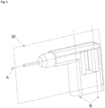
- Fig. 3 shows a schematic representation of a preferred embodiment of a machine tool 10, as well as the clamping of the virtual center plane 20.
- the virtual center plane 20 is preferably spanned by a first axis A and a second axis B.
- the first axis A is preferably the rotation and/or impact axis of the machine tool 10.
- the second axis B is preferably the motor or main handle axis of the machine tool 10.
- the first axis A and the second axis B are stationary preferably perpendicular to one another and thus span the virtual center plane 20.
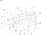
- Fig. 4 shows a schematic representation of a preferred embodiment of a machine tool 10 with a dust collection box 50. Shown in Fig, 4 the tool 12, the handle 28, the suction channel 26 and the working area 16 of the machine tool 10.
- the third axis C which in the in Fig. 4 shown embodiment of the invention runs essentially parallel to the first axis A of the machine tool 10.
- the first axis A and the third axis C run essentially perpendicular to the second axis B.
- the dust-containing air 14 is sucked through the suction channel 26 from the working area 16 of the machine tool 10 in the direction of the dust collection box 10.
- the reason for this is the suction unit 58 of the dust collection box 50, which generates a negative pressure and thereby a suction flow.
- the suction channel 26 has a flow cross section SQ through which the dust-laden air 14 flows in the direction of the dust collection box 50.
- the axis C which preferably runs centrally or centrally through the suction channel 26, is preferably perpendicular to the flow cross section SQ of the suction channel 26.
- the dust-laden air 14 flows along the third axis C, so that a Flow direction of the dust-laden air and the third axis C run essentially parallel or collinear to one another.
- the second axis B runs through the motor 36 of the machine tool 10.
- the second axis B preferably runs through the handle 28 of the machine tool 10. This handle 28 can preferably be designed as a so-called pistol handle.
- the dust collection box 50 has a lower area 68 with an inlet 56, a filter 52 and an outlet 70, as well as an upper area 66.
- the dust-laden air passes from the suction duct 26 of the machine tool 10 via the inlet 56 into the dust collection box 50. There can Some of the dust is deposited in the lowest area of the dust collection box 50, with the air being sucked further towards the suction unit 58 or flowing there due to the negative pressure generated by the suction unit 58.
- the air passes through the transition area between the lower area 68 and the upper area 66 of the dust collection box 50, the filter 52 being arranged in this transition area.
- the filter 52 is there for this set up to filter the dust-laden air, so that in particular low-dust or filtered air reaches the upper area 66 of the dust collection box 50.
- the dust collection box 50 can have various seals 30, 32, 34, with the first seal 30 being designed to direct the dust-laden air 14 into the dust collection box 50. With the second seal 32, the cleaned air can be directed from the filter 52 to a suction unit 58 or fan 58 of the dust collection box 50.
- the third seal 34 is designed to separate the dust collection box 50 into an upper area 66 and a lower area 68 (see Fig. 4 to 7 ).
- the lower area 68 of the dust collection box 50 includes the inlet 56 and the outlet 70 of the dust collection box 50, with the filter 52 being arranged in the area of the outlet 70.
- the filter 52 represents the transition between the lower area 68 and the upper area 66 of the dust collection box 50, with dust-containing air being present in the lower area 68 and low-dust air in the upper area 66.
- the filter 52 is preferably designed as a fin filter with fins 64 and is designed to filter out dust from the air flow. This reduces the dust load in the air when it passes through the filter 52 or during the transition from the lower region 68 to the upper region 66 of the dust collection box 50.
- Fig. 5 shows a schematic representation of a preferred embodiment of a machine tool 10 with a dust collection box 50, as well as its inlet area 56 and outlet area 70.
- a preferred embodiment of the machine tool 10 is shown, which has a tool 12, a handle 28 and a suction channel 26.
- a surface (not shown) can be processed, with this processing producing dust and dirt, which can be sucked out using the dust collection box 50.
- FIG. 5 On the right, upper side of the Fig. 5 a section through the machine tool 10 is shown.
- the sectional view shows the machine tool 10 in the upper area and the dust collection box 50 underneath.
- the dust collection box 50 is divided into an upper area 66 and a lower area 68, with the filter 52 of the dust collection box 50 between the upper area 66 and the lower area 68 arranged.
- a third seal 34 can be provided in the transition area between the lower area 68 and the upper area 66 of the dust collection box 50, which seals the areas 66, 68 of the dust collection box 50 from one another.
- the third seal 34 By providing the third seal 34, the area 68 of the dust collection box 50, in which there is dust-laden air, can be sealed from the area 66 of the dust collection box 50, in which there is low-dust air.
- the virtual level 20 is also shown, which divides the dust collection box 50 or the machine tool 10 into a first half 22 and a second half 24.
- the majority of the filter 52 of the dust collection box 52 is preferably located in the first half 22, while the majority of the inlet region 56 of the dust collection box is provided in the second half 24.
- the inlet region 56 of the dust collection box has a flow or inlet cross section that can have a first center of gravity SP1. If the inlet cross section is, for example, rectangular, the first center of gravity SP1 can correspond, for example, to the intersection of the diagonals of the inlet cross section.
- the inlet area 56 and its first center of gravity SP1 are preferably in the first half 22 of the machine tool 10 or the dust collection box 50.
- a second center of gravity SP2 can be defined for the outlet region 70 of the dust collection box 50, the outlet region 70 and its second center of gravity SP2 preferably being present in the second half 24 of the machine tool 10 or the dust collection box 50.
- FIG. 5 On the right, lower side of the Fig. 5 a further section through the machine tool 10 is shown, this sectional view showing the transition area between the lower area 68 and the upper area 66 of the dust collection box 50.
- the filter 52 and the third seal 34 of the dust collection box 50 can be arranged in this transition area.
- the right, lower side shows the Fig. 5 the arrangement of the inlet area 56 and the outlet area 70 of the dust collection box 50 on the different sides 22, 24 of the dust collection box 50. While the inlet area 56 and the first center of gravity SP1 of the dust collection box 50 are on the first side 22 of the virtual center plane 20, the outlet area 70 and the second center of gravity SP2 of the dust collection box 50 on the second side 24 of the virtual center plane 20.
- Fig. 6 shows a further schematic representation of a preferred embodiment of a machine tool 10 with a dust collection box 50, as well as its inlet area 56 and outlet area 70.
- the lower region 68 of the dust collection box 50 is shown to illustrate the location of the inlet region 56 and the first center of gravity SP1, as well as the position of the outlet region 70 and the second center of gravity SP2.
- the third seal 34 which can represent a sealing plane for sealing the upper region 66 and the lower region 68 of the dust collection box 50 from each other.
- Fig. 7 shows a schematic representation of a preferred dust collection box 50 and its components.
- the filter 52, the outlet region 70 and its center of gravity SP2 are present on the first side 22 of the dust collection box 50, while the inlet region 56 and its center of gravity SP1 are present on the second side 24.
- the virtual center plane 20 divides the dust collection box 50 or the machine tool 10 into two halves 22, 24 in the vertical direction
- the dust collection box 50 is divided in the horizontal direction into an upper area 66 and a lower area 68.
- the filter 52 and the third seal 34 of the dust collection box 50 can be present in the transition area between the areas 66, 68 of the dust collection box 50.
Landscapes
- Engineering & Computer Science (AREA)
- Mechanical Engineering (AREA)
- Auxiliary Devices For Machine Tools (AREA)
- Filtering Of Dispersed Particles In Gases (AREA)
Priority Applications (5)
| Application Number | Priority Date | Filing Date | Title |
|---|---|---|---|
| EP22195277.3A EP4338885A1 (fr) | 2022-09-13 | 2022-09-13 | Machine-outil avec collecteur de poussière et collecteur de poussière |
| CN202380055616.6A CN119546415A (zh) | 2022-09-13 | 2023-08-29 | 具有集尘箱的动力工具以及集尘箱 |
| PCT/EP2023/073736 WO2024056377A1 (fr) | 2022-09-13 | 2023-08-29 | Machine-outil avec boîte de collecte de poussière, et boîte de collecte de poussière |
| US19/106,954 US20260061538A1 (en) | 2022-09-13 | 2023-08-29 | Power tool with a dust collection box, and dust collection box |
| EP23762470.5A EP4587221A1 (fr) | 2022-09-13 | 2023-08-29 | Machine-outil avec boîte de collecte de poussière, et boîte de collecte de poussière |
Applications Claiming Priority (1)
| Application Number | Priority Date | Filing Date | Title |
|---|---|---|---|
| EP22195277.3A EP4338885A1 (fr) | 2022-09-13 | 2022-09-13 | Machine-outil avec collecteur de poussière et collecteur de poussière |
Publications (1)
| Publication Number | Publication Date |
|---|---|
| EP4338885A1 true EP4338885A1 (fr) | 2024-03-20 |
Family
ID=83361108
Family Applications (2)
| Application Number | Title | Priority Date | Filing Date |
|---|---|---|---|
| EP22195277.3A Withdrawn EP4338885A1 (fr) | 2022-09-13 | 2022-09-13 | Machine-outil avec collecteur de poussière et collecteur de poussière |
| EP23762470.5A Pending EP4587221A1 (fr) | 2022-09-13 | 2023-08-29 | Machine-outil avec boîte de collecte de poussière, et boîte de collecte de poussière |
Family Applications After (1)
| Application Number | Title | Priority Date | Filing Date |
|---|---|---|---|
| EP23762470.5A Pending EP4587221A1 (fr) | 2022-09-13 | 2023-08-29 | Machine-outil avec boîte de collecte de poussière, et boîte de collecte de poussière |
Country Status (4)
| Country | Link |
|---|---|
| US (1) | US20260061538A1 (fr) |
| EP (2) | EP4338885A1 (fr) |
| CN (1) | CN119546415A (fr) |
| WO (1) | WO2024056377A1 (fr) |
Citations (2)
| Publication number | Priority date | Publication date | Assignee | Title |
|---|---|---|---|---|
| US20120273243A1 (en) * | 2011-04-26 | 2012-11-01 | Makita Corporation | Dust collection device for power tool and power tool |
| US20190314943A1 (en) * | 2016-01-20 | 2019-10-17 | Makita Corporation | Dust collector for electric power tool, electric power tool, and dust collection system |
Family Cites Families (32)
| Publication number | Priority date | Publication date | Assignee | Title |
|---|---|---|---|---|
| DE2705388C2 (de) * | 1977-02-09 | 1986-06-05 | Robert Bosch Gmbh, 7000 Stuttgart | Vorrichtung an einer Handwerkzeugmaschine zum Absaugen des Bohrkleins |
| JPH0773817B2 (ja) * | 1989-10-14 | 1995-08-09 | 日立工機株式会社 | 集じんハンマドリル |
| DE4335417B4 (de) * | 1993-10-18 | 2006-11-30 | Hilti Ag | Absaugeinrichtung eines Bohr- oder Meisselgerätes |
| DE19831383A1 (de) * | 1998-07-14 | 2000-01-20 | Bosch Gmbh Robert | Handwerkzeugmaschine mit Staubabsaugung |
| DE19924547A1 (de) * | 1999-05-28 | 2000-11-30 | Bosch Gmbh Robert | Handwerkzeugmaschine mit Staubabsaugung |
| DE10005976A1 (de) * | 2000-02-10 | 2001-08-16 | Bosch Gmbh Robert | Staubbehälter |
| DE10041906B4 (de) * | 2000-08-25 | 2011-06-09 | Hilti Aktiengesellschaft | Schleifgerät mit Staubabsaugung |
| DE10112129A1 (de) * | 2001-03-14 | 2002-09-19 | Hilti Ag | Saugmodul |
| GB0305846D0 (en) * | 2003-03-14 | 2003-04-16 | Black & Decker Inc | Dust extraction shrould for a power tool |
| ITMI20030961A1 (it) * | 2003-05-14 | 2004-11-15 | Guido Valentini | Utensile motorizzato con capacita' di aspirazione e raccolta polvere. |
| DE102004056856A1 (de) * | 2004-11-25 | 2006-06-01 | Hilti Ag | Grobabscheider |
| DE102006029624A1 (de) * | 2006-06-28 | 2008-01-03 | Robert Bosch Gmbh | Staubauffangvorrichtung für eine Elktrohandwerkzeugmaschine |
| DE102006029625A1 (de) * | 2006-06-28 | 2008-01-03 | Robert Bosch Gmbh | Absaugvorrichtung einer Elektrohandwerkzeugmaschine sowie Elektrohandwerkzeugmaschine mit Absaugvorrichtung |
| DE102006048719A1 (de) * | 2006-10-16 | 2008-04-17 | Robert Bosch Gmbh | System mit einer Handwerkzeugmaschine |
| DE202006017584U1 (de) * | 2006-11-17 | 2007-02-08 | Metabowerke Gmbh | Absaugeinrichtung für ein motorisch angetriebenes Handwerkzeuggerät |
| DE102007019704A1 (de) * | 2007-04-26 | 2008-11-06 | Siegfried Keusch | Vorrichtung zum Absaugen des Bohrstaubes einer handelsüblichen Handbohrmaschine |
| US8997887B2 (en) * | 2008-12-19 | 2015-04-07 | Makita Corporation | Power tool |
| DE102009001502A1 (de) * | 2009-03-12 | 2010-09-16 | Robert Bosch Gmbh | Handwerkzeugmaschinenvorrichtung |
| JP5448951B2 (ja) * | 2010-03-16 | 2014-03-19 | 株式会社マキタ | アタッチメント付き電動工具の駆動源供給システム |
| DE102011087361B3 (de) * | 2011-11-29 | 2013-01-31 | Hilti Aktiengesellschaft | Absaugvorrichtung und Steuerungsverfahren |
| WO2015122539A1 (fr) * | 2014-02-17 | 2015-08-20 | 株式会社マキタ | Collecteur de poussière et outil de travail muni d'un collecteur de poussière |
| US10493577B2 (en) * | 2016-07-21 | 2019-12-03 | Makita Corporation | Dust collection device for electric power tool, electric power tool, and dust collection system |
| DE102017123102A1 (de) * | 2016-11-04 | 2018-05-09 | Makita Corporation | Kraftwerkzeug |
| GB201700637D0 (en) * | 2017-01-13 | 2017-03-01 | Black & Decker Inc | Dust collection box |
| DE102017201558A1 (de) * | 2017-01-31 | 2018-08-02 | Robert Bosch Gmbh | Zubehörvorrichtung für eine Handwerkzeugmaschine |
| JP6927808B2 (ja) * | 2017-08-31 | 2021-09-01 | 株式会社マキタ | 電動工具用集塵装置及び電動工具 |
| CN108705123A (zh) * | 2018-07-13 | 2018-10-26 | 高邮市力博机床附件厂 | 一种具有防尘功能的电钻 |
| DE102018215308A1 (de) * | 2018-09-10 | 2020-03-12 | Robert Bosch Gmbh | Staubsaugvorrichtung |
| DE102020213170A1 (de) * | 2020-10-19 | 2022-04-21 | Robert Bosch Gesellschaft mit beschränkter Haftung | Absaugvorrichtung |
| WO2024038822A1 (fr) * | 2022-08-19 | 2024-02-22 | 工機ホールディングス株式会社 | Machine de travail |
| US12368347B2 (en) * | 2022-12-01 | 2025-07-22 | Norbar Torque Tools Limited | Cooling electronics of power tools |
| CN115958567B (zh) * | 2023-01-06 | 2025-06-20 | 江苏东成工具科技有限公司 | 集尘装置 |
-
2022
- 2022-09-13 EP EP22195277.3A patent/EP4338885A1/fr not_active Withdrawn
-
2023
- 2023-08-29 CN CN202380055616.6A patent/CN119546415A/zh active Pending
- 2023-08-29 WO PCT/EP2023/073736 patent/WO2024056377A1/fr not_active Ceased
- 2023-08-29 US US19/106,954 patent/US20260061538A1/en active Pending
- 2023-08-29 EP EP23762470.5A patent/EP4587221A1/fr active Pending
Patent Citations (2)
| Publication number | Priority date | Publication date | Assignee | Title |
|---|---|---|---|---|
| US20120273243A1 (en) * | 2011-04-26 | 2012-11-01 | Makita Corporation | Dust collection device for power tool and power tool |
| US20190314943A1 (en) * | 2016-01-20 | 2019-10-17 | Makita Corporation | Dust collector for electric power tool, electric power tool, and dust collection system |
Also Published As
| Publication number | Publication date |
|---|---|
| EP4587221A1 (fr) | 2025-07-23 |
| US20260061538A1 (en) | 2026-03-05 |
| WO2024056377A1 (fr) | 2024-03-21 |
| CN119546415A (zh) | 2025-02-28 |
Similar Documents
| Publication | Publication Date | Title |
|---|---|---|
| DE102004050911B4 (de) | Staubsammelvorrichtung für einen Staubsauger | |
| DE102004034015B4 (de) | Wirbelungs-Staubsammelvorrichtung für einen Staubsauger | |
| EP4216784A1 (fr) | Dispositif de filtration et procédé de nettoyage y relatif | |
| DE10053582A1 (de) | Handwerkzeugmaschine mit einer Staubabsaugeinrichtung | |
| EP1661662B1 (fr) | Dispositif de séparation grossier pour des particules aspirées | |
| DE102016118807A1 (de) | Rückspülbarer Luftfilter und Staubsauger mit einem rückspülbaren Luftfilter | |
| DE102016119194A1 (de) | Staubsauger mit einem Filterelement | |
| DE102009001502A1 (de) | Handwerkzeugmaschinenvorrichtung | |
| WO2021254818A1 (fr) | Dispositif de dépoussiérage pour machine-outil | |
| EP4167820B1 (fr) | Dispositif de collecte de poussière pour une machine-outil | |
| DE2424179C3 (de) | Vorrichtung zur Trennung von Luft und Staub | |
| WO2024056377A1 (fr) | Machine-outil avec boîte de collecte de poussière, et boîte de collecte de poussière | |
| EP3965995B1 (fr) | Dispositif de hotte aspirante des poussières pour un appareil-outil ainsi que son utilisation et son procédé d'aspiration des poussières | |
| DE102014116280A1 (de) | Saugdüse | |
| EP4452033A1 (fr) | Unité de nettoyage de filtre, aspirateur et procédé de nettoyage de filtre d'aspirateur | |
| EP3354178B1 (fr) | Aspirateur | |
| DE60026397T2 (de) | Staubsauger mit Flüssigkeitsbad | |
| EP2659821B1 (fr) | Dimensions d'un séparateur à tube vortex | |
| DE102021201053B4 (de) | Saugvorrichtung mit innenliegendem Gebläse | |
| EP4009845B1 (fr) | Dispositif de compensation des surpressions au coup de bélier | |
| EP3881745B1 (fr) | Buse de sol pour un aspirateur | |
| EP2534990A2 (fr) | Buse de sol pour un aspirateur et aspirateur doté d'une telle buse de sol | |
| EP4449963A1 (fr) | Appareil d'aspiration et son procédé de fonctionnement | |
| CH705017A1 (de) | Wassersammelring zum Kühlwasserabtransport bei Bohrungen an Gebäuden. | |
| DE102015100873A1 (de) | Saugdüse |
Legal Events
| Date | Code | Title | Description |
|---|---|---|---|
| PUAI | Public reference made under article 153(3) epc to a published international application that has entered the european phase |
Free format text: ORIGINAL CODE: 0009012 |
|
| STAA | Information on the status of an ep patent application or granted ep patent |
Free format text: STATUS: THE APPLICATION HAS BEEN PUBLISHED |
|
| AK | Designated contracting states |
Kind code of ref document: A1 Designated state(s): AL AT BE BG CH CY CZ DE DK EE ES FI FR GB GR HR HU IE IS IT LI LT LU LV MC MK MT NL NO PL PT RO RS SE SI SK SM TR |
|
| STAA | Information on the status of an ep patent application or granted ep patent |
Free format text: STATUS: THE APPLICATION IS DEEMED TO BE WITHDRAWN |
|
| 18D | Application deemed to be withdrawn |
Effective date: 20240921 |