EP4338905A1 - Dispositif et procédé de traitement d'un matériau - Google Patents
Dispositif et procédé de traitement d'un matériau Download PDFInfo
- Publication number
- EP4338905A1 EP4338905A1 EP22195424.1A EP22195424A EP4338905A1 EP 4338905 A1 EP4338905 A1 EP 4338905A1 EP 22195424 A EP22195424 A EP 22195424A EP 4338905 A1 EP4338905 A1 EP 4338905A1
- Authority
- EP
- European Patent Office
- Prior art keywords
- carriers
- push rod
- carrier
- arm
- moved
- Prior art date
- Legal status (The legal status is an assumption and is not a legal conclusion. Google has not performed a legal analysis and makes no representation as to the accuracy of the status listed.)
- Granted
Links
Images


Classifications
-
- B—PERFORMING OPERATIONS; TRANSPORTING
- B26—HAND CUTTING TOOLS; CUTTING; SEVERING
- B26D—CUTTING; DETAILS COMMON TO MACHINES FOR PERFORATING, PUNCHING, CUTTING-OUT, STAMPING-OUT OR SEVERING
- B26D7/00—Details of apparatus for cutting, cutting-out, stamping-out, punching, perforating, or severing by means other than cutting
- B26D7/26—Means for mounting or adjusting the cutting member; Means for adjusting the stroke of the cutting member
- B26D7/2628—Means for adjusting the position of the cutting member
-
- B—PERFORMING OPERATIONS; TRANSPORTING
- B21—MECHANICAL METAL-WORKING WITHOUT ESSENTIALLY REMOVING MATERIAL; PUNCHING METAL
- B21D—WORKING OR PROCESSING OF SHEET METAL OR METAL TUBES, RODS OR PROFILES WITHOUT ESSENTIALLY REMOVING MATERIAL; PUNCHING METAL
- B21D28/00—Shaping by press-cutting; Perforating
- B21D28/02—Punching blanks or articles with or without obtaining scrap; Notching
- B21D28/06—Making more than one part out of the same blank; Scrapless working
-
- B—PERFORMING OPERATIONS; TRANSPORTING
- B21—MECHANICAL METAL-WORKING WITHOUT ESSENTIALLY REMOVING MATERIAL; PUNCHING METAL
- B21D—WORKING OR PROCESSING OF SHEET METAL OR METAL TUBES, RODS OR PROFILES WITHOUT ESSENTIALLY REMOVING MATERIAL; PUNCHING METAL
- B21D28/00—Shaping by press-cutting; Perforating
- B21D28/24—Perforating, i.e. punching holes
- B21D28/246—Selection of punches
-
- B—PERFORMING OPERATIONS; TRANSPORTING
- B21—MECHANICAL METAL-WORKING WITHOUT ESSENTIALLY REMOVING MATERIAL; PUNCHING METAL
- B21D—WORKING OR PROCESSING OF SHEET METAL OR METAL TUBES, RODS OR PROFILES WITHOUT ESSENTIALLY REMOVING MATERIAL; PUNCHING METAL
- B21D37/00—Tools as parts of machines covered by this subclass
- B21D37/04—Movable or exchangeable mountings for tools
-
- B—PERFORMING OPERATIONS; TRANSPORTING
- B26—HAND CUTTING TOOLS; CUTTING; SEVERING
- B26D—CUTTING; DETAILS COMMON TO MACHINES FOR PERFORATING, PUNCHING, CUTTING-OUT, STAMPING-OUT OR SEVERING
- B26D5/00—Arrangements for operating and controlling machines or devices for cutting, cutting-out, stamping-out, punching, perforating, or severing by means other than cutting
- B26D5/02—Means for moving the cutting member into its operative position for cutting
-
- B—PERFORMING OPERATIONS; TRANSPORTING
- B30—PRESSES
- B30B—PRESSES IN GENERAL
- B30B15/00—Details of, or accessories for, presses; Auxiliary measures in connection with pressing
- B30B15/04—Frames; Guides
-
- B—PERFORMING OPERATIONS; TRANSPORTING
- B21—MECHANICAL METAL-WORKING WITHOUT ESSENTIALLY REMOVING MATERIAL; PUNCHING METAL
- B21D—WORKING OR PROCESSING OF SHEET METAL OR METAL TUBES, RODS OR PROFILES WITHOUT ESSENTIALLY REMOVING MATERIAL; PUNCHING METAL
- B21D22/00—Shaping without cutting, by stamping, spinning, or deep-drawing
- B21D22/20—Deep-drawing
-
- B—PERFORMING OPERATIONS; TRANSPORTING
- B23—MACHINE TOOLS; METAL-WORKING NOT OTHERWISE PROVIDED FOR
- B23Q—DETAILS, COMPONENTS, OR ACCESSORIES FOR MACHINE TOOLS, e.g. ARRANGEMENTS FOR COPYING OR CONTROLLING; MACHINE TOOLS IN GENERAL CHARACTERISED BY THE CONSTRUCTION OF PARTICULAR DETAILS OR COMPONENTS; COMBINATIONS OR ASSOCIATIONS OF METAL-WORKING MACHINES, NOT DIRECTED TO A PARTICULAR RESULT
- B23Q1/00—Members which are comprised in the general build-up of a form of machine, particularly relatively large fixed members
- B23Q1/25—Movable or adjustable work or tool supports
- B23Q1/26—Movable or adjustable work or tool supports characterised by constructional features relating to the co-operation of relatively movable members; Means for preventing relative movement of such members
- B23Q1/28—Means for securing sliding members in any desired position
- B23Q1/285—Means for securing sliding members in any desired position for securing two or more members simultaneously or selectively
-
- B—PERFORMING OPERATIONS; TRANSPORTING
- B26—HAND CUTTING TOOLS; CUTTING; SEVERING
- B26F—PERFORATING; PUNCHING; CUTTING-OUT; STAMPING-OUT; SEVERING BY MEANS OTHER THAN CUTTING
- B26F1/00—Perforating; Punching; Cutting-out; Stamping-out; Apparatus therefor
- B26F1/02—Perforating by punching, e.g. with relatively-reciprocating punch and bed
Definitions
- the invention relates to a device and a method for processing a material, in particular a strip material, in which several carriers with processing tools are used, which can be positioned at different distances from one another.
- the US 4,604,934 discloses a system for positioning multiple carts along a bridge spanning a work surface.
- the outermost car is connected to a drive device, the other cars can be selectively coupled to the neighboring cars.
- Each cart (except the outermost one) can be clamped to a pole.
- To position the carriages they are first pushed together in a starting position and then pulled forward in the coupled configuration using the drive device; The rearmost car is then gradually released from the train at the corresponding position and clamped to the pole.
- the cars have a rectangular base body.
- the EP 0 997 444 (HEGLA ) describes a method and a device for positioning several processing heads of a multi-head processing machine that can be moved at least along two spatial axes. There will be one fully automatic positioning of the processing heads along a bridge spanning a cutting table.
- the processing heads are assigned to individual carrier carriages and are initially arranged as close to one another as possible for positioning.
- the carriages are then moved by one of the carriages, which can be driven along the longitudinal axis of the bridge; After reaching the respective target position, the carriage in question is locked with respect to the longitudinal axis of the bridge, released from the assembly and coupled to the carriages that have already been positioned.
- two adjacent carrier carriages are each connected via a sliding rod, with one of the carriages being able to be clamped to the sliding rod using a clamping device.
- the processing heads are in the form of slides to which processing tools can be attached.
- the object of the invention is to create a device belonging to the technical field mentioned at the beginning, which is suitable for processing a material, in particular a strip material, whereby a distance between the supports or the processing tools arranged thereon can be changed.
- the device comprises at least two carriers, each with at least one processing tool for the material, at least one linear guide on which the at least two carriers are arranged in a linearly displaceable manner, and a push rod driven movably in two opposite directions along the at least one linear guide.
- the at least two carriers each have a coupling device with which each of the at least two carriers can be selectively coupled to the push rod.
- the device has a control with which the coupling devices can be controlled, so that by means of the push rod the at least two carriers can be moved together along the at least one linear guide or only one or more defined ones of the at least two carriers can be moved, so that a distance can be changed between the at least two carriers.
- the device preferably has a frame on which the individual components of the device are arranged or supported.
- the frame preferably has bases or feet with which the frame can be placed on a floor.
- the processing tools are preferably punching tools and/or deep-drawing tools. This allows, for example, shaped parts to be cut from the material and then shaped three-dimensionally. Alternatively, however, other processing tools can also be arranged on the at least two carriers, such as. B. Pressing tools.
- the processing tools can carry out several processing steps when processing the material, for example the already mentioned sequence of processing steps of cutting and three-dimensional shaping. The sequence of processing steps required to process the material results in a processing cycle. In the example already mentioned for the production of a deep-drawn molded part, the processing steps of cutting and subsequent three-dimensional shaping together form a processing cycle.
- the strip material processed with the processing tools is preferably a metal, paper, cardboard or plastic strip.
- the thickness of the strip material can vary, but is preferably in the range of 0.1 mm to 10 mm.
- the at least two carriers preferably consist of a metal or a metal alloy, in particular aluminum, steel or stainless steel.
- the at least two carriers can preferably be made of plastic, in particular a reinforced plastic, such as a plastic reinforced with glass or carbon fibers.
- the at least two carriers have at least one plain bearing, at least one roller or the like so that the at least two carriers can move on the at least one linear guide are arranged.
- the at least one linear guide accordingly preferably has a plain bearing, a guide rail or a guide groove.
- the device preferably comprises more than two carriers, in particular more than 5 carriers, preferably 10, 11 or 12 carriers.
- the maximum number of supports that the device has usually depends on the width of the material to be processed and the size or diameter of the processing tools, although the device can also have fewer depending on the intended processing of the material or depending on the method used Carriers can have as the maximum number of carriers.
- the device can have more than one linear guide, which are arranged parallel and in particular at a distance from one another.
- the at least one linear guide extends in the horizontal direction when the device is used as intended. If there is more than one linear guide, the linear guides are preferably arranged at a distance from one another. When the device is used as intended, the linear guides are preferably spaced apart from one another in the vertical direction. The linear guides can be arranged directly one below the other in the vertical direction, i.e. in the same vertically arranged plane. However, the linear guides are preferably arranged offset from one another in the horizontal direction, i.e. when the device is used as intended, they are not in the same vertical plane, but rather in vertical planes that are horizontally offset from one another.
- the device particularly preferably has two parallel linear guides.
- the at least one linear guide preferably has stops at both ends which limit the movement of the at least two carriers to a defined displacement range.
- the push rod is preferably arranged parallel to the at least one linear guide and is movably supported on the at least one linear guide or on the frame of the device by means of at least one bearing, in particular a plain bearing or a roller bearing.
- the push rod is operated by means of a drive, in particular by means of an electric motor, an electromechanical drive, a pneumatic or hydraulic drive moves in the two opposite directions.
- the push rod preferably has a round cross section.
- the push rod can also have a different cross section, e.g. square, rectangular, oval or polygonal.
- the push rod is preferably made of a metal or a metal alloy so that it is as rigid as possible.
- the push rod can also consist of another material, for example a polymer, in particular a carbon fiber reinforced plastic.
- the coupling devices have means with which the respective coupling device can be selectively coupled to the push rod.
- the coupling is preferably non-positive and/or positive, with the coupling devices having appropriate means to establish a non-positive and/or positive connection with the push rod.
- the coupling can also take place using magnetic force, for example via an electromagnet.
- a carrier By coupling with the push rod, a carrier can thus be moved along the at least one linear guide.
- a carrier By selectively decoupling a carrier from the push rod, it can be positioned at a specific position along the at least one linear guide without being moved by further movements of the push rod itself.
- Such a selective system can be used, for example, to change the distance between the at least two carriers or, depending on the processing of the strip material, to leave one or more carriers that do not need to be used, in particular stationary, in a parking position.
- the control preferably has at least one microcontroller or microprocessor. Furthermore, the control preferably has a non-volatile memory as well as input and output means, for example in the form of a touchscreen.
- the controller is preferably connected to the coupling devices of the at least two carriers via at least one data connection, for example a data cable connection or a wireless data connection, so that by means of the Control each carrier can be selectively coupled to or decoupled from the push rod by the coupling device arranged thereon.
- the control is further preferably connected to the drive of the push rod and to the processing tools. This means that the movement of the push rod and the function of the processing tools can be controlled using the control.
- a first carrier can be coupled to the push rod, while the at least one further carrier is decoupled from the push rod.
- the distance between the first carrier and a carrier adjacent to it can be changed easily and automatically. If the device has more than two carriers, a distance of each carrier from an adjacent carrier can be changed in the manner described. With the change in the distance between the at least two carriers from one another, the distance between the processing tools arranged on the carriers is of course also changed.
- a change in the distance may become necessary, for example, if, when using the device for cutting molded parts from a strip material, molded parts with a different size and/or shape are to be punched out. By changing the distance, an overlap of the punched-out molded parts on the strip material or excessive waste of the strip material remaining after cutting the molded parts can be avoided.
- the carriers By coupling all carriers to the push rod, they can all be moved together using the push rod.
- the movement preferably takes place alternately in one of the opposite directions.
- the coupling devices of the at least two carriers preferably have a rod clamping, in particular a pneumatic, magnetic, electrical or spring-loaded rod clamping, which each interact selectively with the push rod.
- the carriers are coupled to the push rod by a clamping force, i.e. by frictional connection.
- the rod clamp preferably has an opening through which the push rod is pushed through, with at least one clamping element being arranged in the area of the opening, which can be brought into an extended state, where it presses against the push rod in order to bring the push rod into frictional connection with the rod clamp bring to.
- the at least one clamping element is preferably biased by a spring element into a retracted state, in which the at least one clamping element does not interact with the push rod, i.e. is not pressed onto it.
- the at least one clamping element is moved from the retracted state to the extended state in particular by an actuator, preferably by a pneumatic cylinder.
- the at least one clamping element consists of or comprises a material with a high coefficient of static friction, for example rubber, on a surface facing the push rod, in order to ensure the most non-slip coupling with the push rod.
- the push rod is preferably connected at one end to a carriage which can be moved linearly in two directions via an electrical or electromechanical drive along an axis that runs parallel to the at least one linear guide.
- the carriage moves in a defined range of movement, which is in particular laterally in an imaginary extension of the axis of expansion of the at least one linear guide on the frame of the device lies, and preferably runs by means of rollers on at least one guide rail or in at least one guide groove.
- the drive can be located directly on the cart.
- the drive is preferably arranged on the frame of the device and is operatively connected to the carriage via a drive member, for example a chain.
- the drive or the carriage preferably has means with which the position of the carriage along at least one guide rail or guide groove can be determined.
- the drive of the carriage can include, for example, a stepper motor or servo motor, or a roller of the carriage can have a rotary encoder disk with which the angle of rotation of the roller can be measured.
- sensors can also be present with which the relative position of the carriage to the sensor can be measured, e.g. an ultrasonic sensor.
- the push rod is also arranged on a carriage at its second end.
- the push rod can also be guided in a plain or roller bearing at the second end.
- the drive of the car is preferably connected to the controller by means of a line and is controlled by it. Any existing sensor for the encoder disk or another sensor with which the position of the carriage can be measured is also preferably connected to the control.
- the carriage is preferably movable via a toothed belt, which is connected to an output of an electric motor, in particular a servo motor, or by a linear motor. This enables a secure and slip-free connection between the drive and the carriage.
- the toothed belt preferably runs over a deflection roller, which is also arranged at the end of the movement range of the carriage, that is to say at one end of the at least one guide rail or guide groove. Attaching the deflection roller to the frame forms a stop for the car.
- the deflection roller is preferably arranged between the movement range of the carriage and the at least one linear guide on the frame.
- the deflection roller or its attachment preferably forms one Stop for at least two carriers.
- the electric motor is preferably arranged at the other end of the movement range of the carriage.
- the toothed belt is preferably firmly connected to the carriage, for example by a screw or clamp connection.
- At least one locking element is preferably arranged at a defined position along the at least one linear guide, which interacts with a positioning element of one of the at least two carriers in order to lock it at the defined position.
- At least one of the at least two carriers can be locked at the defined position so that it cannot move.
- the at least one locking element can be attached to the at least one linear guide or to the frame of the device.
- the device preferably has a locking element for each carrier.
- the at least one locking element is arranged at a parking position of at least one of the at least two carriers along the at least one linear guide. This means that this carrier can be locked in the parking position, e.g. if fewer processing tools than available are required to process the material.
- the at least one locking element and the positioning element work together in a form-fitting manner.
- the locking element and positioning element can also interact by means of magnetic force, for example by an electromagnet.
- the at least one locking element has a positioning pin which can be moved from a retracted state to an extended state, in which the positioning pin engages in the positioning element of at least one carrier.
- the positioning element preferably has a cylindrical receptacle for the positioning pin.
- the receptacle preferably has a conical opening, so that the positioning pin is guided into the opening when moving into the extended state even if the carrier or the positioning element arranged on it is not exactly in the defined position.
- the at least one positioning pin is biased in the retracted state by means of a spring element and can be selectively moved into the extended state by means of an actuator, in particular a pneumatic actuator.
- the correct movement of the positioning pin into the retracted and/or extended state can preferably be monitored by a sensor.
- the at least two carriers each have at least one carriage, which is displaceably arranged on the at least one linear guide.
- the at least one carriage preferably has at least one plain bearing, at least one roller or at least one wheel, which runs on the linear guide.
- the at least two carriers each have the same number of carriages as the number of linear guides of the device.
- the at least one plain bearing of the at least one carriage preferably slides on a plain bearing or a surface of the at least one linear guide.
- the linear guide preferably has lateral guides for the at least one slide or the at least one plain bearing. If the at least one carriage has at least one roller or at least one wheel, this preferably runs in at least one guide groove or on at least one guide rail of the at least one linear guide.
- the at least two carriers each have at least one processing tool for cutting and/or three-dimensionally shaping a strip material.
- the at least two carriers preferably have the same processing tools, so that the same work steps can be carried out in parallel on the material per work cycle by means of the processing tools arranged on the at least two carriers.
- the device has two parallel linear guides, which are arranged at a first distance from one another.
- the first distance preferably extends in the vertical direction when the device is used as intended.
- the two linear guides are arranged offset from one another in the horizontal direction at a second distance from one another.
- the device preferably has conveying means for feeding a strip material to the processing tools.
- the conveying means can be designed differently depending on the type of strip material to be processed with the device.
- the conveying means preferably has at least one driven roller or roller on which the strip material rests. Pairs of rollers or rollers between which the strip material passes are also possible.
- the device can also have a conveyor belt or a roller belt on which the strip material rests.
- the device can also preferably have vacuum belts with which the belt material can be conveyed.
- the device can preferably have a suspension to which a roll of the strip material can be attached, the strip material being unwound from the roll and fed to the processing tools.
- the conveying means are designed such that the strip material is fed to the processing tools in the direction of extension of the first and second arms and in the direction of the connecting arm.
- the device preferably has at least one cutting element with which the strip material can be cut to length after each processing cycle or after a certain number of processing cycles, so that the strip material does not run onto the connecting arms of the at least two carriers.
- the conveying means are further configured to convey the strip material by a certain distance after each processing cycle, so that unprocessed strip material is available for the following processing cycle.
- the conveyor means moves the strip material by at least half the diameter of the circular shaped parts after a processing cycle.
- the present invention further relates to a method for processing, in particular for cutting and/or three-dimensional shaping, of a strip material using a device according to the description above. After each processing cycle of the strip material by the processing tools, the at least two carriers are moved together by means of the push rod alternately in a first direction and in a second direction opposite to the first direction by a first distance.
- a processing cycle includes all processing steps that are necessary, for example, to produce a molded part from the strip material, for example cutting out the molded part and any subsequent deep-drawing step.
- all carriers of the device are moved together, for this purpose all carriers are coupled to the push rod by means of their respective coupling device.
- the strip material is processed with the processing tools of all carriers during each processing cycle.
- the at least one processing tool of at least one carrier cannot process the strip material in every second processing cycle.
- the method can also be used to process strip material that is not wide enough to be processed by the processing tools of all carriers when the carriers are offset by the first distance.
- circular shaped parts are punched from the strip material and the at least two carriers are moved after each punching process, the first distance corresponding to at least half the diameter of the circular shaped parts.
- the strip material is preferably moved by conveying means after each processing cycle by a second distance, which corresponds to at least half the diameter of the circular molded parts.
- the device can be used to process a strip material with different processing tools.
- the processing tools or components thereof attached to the at least two carriers can be replaced. If, for example, punching tools are attached to the at least two carriers, when the punching dies are replaced, the distance between the carriers can be adjusted according to the size of the replaced punching dies.
- the distance between all carriers is preferably set the same.
- the distance between two adjacent supports can be set differently.
- step g) is carried out until the carrier that is adjacent to the carrier closest to the stop element has been moved.
- the support closest to the stop element is not moved when the distance between the at least two supports is changed. This means that the distance can be changed more quickly than if all the carriers were moved for this purpose.
- all carriers are preferably locked in their position by means of the engagement of a locking element in positioning elements of the carrier, with the positioning pin of the carrier to be moved being retracted before moving the push rod in step f) or in step g). to unlock the respective carrier.
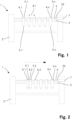
- the Fig. 1 shows a schematic representation of a first embodiment of a device 1 according to the invention.
- the device 1 comprises a frame 2 with which the device 1 can be placed on a floor and on which the components of the device 1 are arranged.
- the device 1 also has a linear guide 3 on which several carriers 4.1 - 4.n are movably arranged.
- a processing tool 5.1 - 5.n is attached to each of the supports 4.1 - 4.n.
- a material, in particular a strip material, can be processed using the processing tools 5.1 - 5.n.
- the device 1 also has a push rod 6, which is arranged parallel to the linear guide 3.
- the push rod 6 is mounted movably in two directions and is set in motion by a drive 7.
- Each carrier 4.1 - 4.n has a coupling device 9.1 - 9.n.
- each carrier 4.1 - 4.n can be selectively coupled to the push rod 6.
- the respective carrier 4.1 - 4.n is moved along the linear guide 3 by the push rod 6.
- the device 1 also has a stop element 25, which limits the movement of the carriers 4.1 - 4.n.
- the carriers 4.1 - 4.n are arranged at a first distance A1 from one another.
- the Fig. 2 shows a first step of the method according to the invention for changing the distance between the supports 4.1 - 4.n, which on the Fig. 2 are arranged at a first distance A1 from one another.
- this step all coupling devices 9.1 - 9.n are first released and the push rod 6 is moved in a first direction, which corresponds to Fig. 2 is opposite to the arrow shown, moved to an end position.
- a first carrier 4.1 which is furthest away from the stop element 25, is then coupled to the push rod 6 by means of its coupling device 9.1.
- the push rod is moved by the drive 7 in a second direction, which is opposite to the first direction and is indicated by the arrow on the Fig. 2 is symbolized, moves.
- the first carrier 4.1 moves onto a second carrier 4.2 adjacent to it and then pulls it along in the second direction.
- the second carrier 4.2 then moves onto another carrier 4.3 adjacent to it and so on.
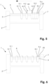
- the carrier train moves onto the carrier 9.n that is closest to the stop element 25 and pulls it with it until it moves onto the stop element 25, as shown in FIG Fig. 3 will be shown.
- the coupling device 9.1 of the first carrier 4.1 is decoupled from the push rod 3 and the push rod 3 is moved in the second direction to a basic position.
- the first carrier 4.1 is then coupled again to the push rod 3 by means of its coupling device 9.1 and the push rod 3 with the first carrier 4.1 coupled thereto is moved by the drive 7 in the first direction by a predefined distance A2, as shown on the Fig. 4 is shown.
- the predefined distance A2 corresponds to the newly set distance between the supports 4.1 - 4.n.
- the carrier 4.2 adjacent to the first carrier 4.1 is then coupled to the push rod 6 by means of its coupling device 9.2 and the push rod with the first carrier 4.1 and the second carrier 4.2 coupled thereto is moved by the predefined distance A2 in the first direction.
- the remaining carriers 4.3 - 4.n are sequentially coupled to the push rod via the corresponding coupling device 9.3 - 9.n after the push rod has moved by the predetermined distance A2 and these are then moved in the first direction by the second distance A2, as this on the Fig. 5 is shown.
- This Sequential coupling and moving is repeated until all carriers 4.1 - 4.n are spaced apart from each other by the predefined distance A2.
- the carrier 4.n closest to the stop element 25 does not have to be moved, but can, as shown on the Fig. 6 shown, remain in its position.
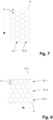
- the Fig. 7 shows a strip material 8, which was partially processed with a device 1 according to the invention.
- the processing tools 5.1 - 5.n and the carriers 4.1 - 4.n are punching tools with which circular shaped parts are punched out of the strip material.
- the circular shaped parts all have the same diameter D.
- the carriers 4.1 - 4.n are all arranged at the same distance from one another when processing the strip material 8. After each processing cycle, all carriers 4.1 - 4.n are moved alternately in the first and second directions by a defined first distance, which is slightly larger than half the diameter D of the circular molded parts.
- the strip material 8 is moved to the left in the viewing direction by a second distance, which is also slightly larger than half the diameter D of the circular molded parts.
- the circular shaped parts can be punched out of the strip material 8 offset from one another in a material-saving manner.
- the offset can be recognized particularly well by the dashed line, which traces the displacement of the center of the lowest circular molding.
- the first distance and the second distance are each more than half the diameter D of the circular molded parts, so that it can be ensured that there are no overlaps of the molded parts.
- the Fig. 8 illustrates a strip material 8, which is used with a method according to Fig. 7 alternative procedures have been partially processed.
- the at least one processing tool 5.1 of one of the outer supports 4.1 is not used in every second processing cycle.
- one fewer circular molded part in a row 10.1 is produced every second work cycle.
- the number of carriers 4.1 - 4.n for the disclosed method can vary depending on the width of the strip material 8 and the dimension of the at least one processing tool 5.1 - 5.n. In the process, the processing tools 5 of more than just one carrier 4.1 - 4.n cannot be used in one processing cycle. It should also be noted that, depending on the width of the strip material 8, one or more carriers 4.1 - 4.n can remain in a parking position and are not moved with the push rod 6. Other processing of the strip material 8 can also be carried out using the disclosed method, for example three-dimensional shaping or embossing.
- the Fig. 9 shows a second embodiment of a device 1 according to the invention.
- the device 1 has a frame 2 with which the device 1 stands on the floor and to which the individual components of the device 1 are attached.
- the device 1 further comprises two linear guides 3.1, 3.2 which are arranged parallel to one another and at a first distance from one another.
- the carriers 4.1 - 4.n are movable using two carriages (see Fig. 10 ) arranged on the two parallel linear guides 3.1, 3.2.
- the carriers 4.1 - 4.n can be moved along the linear guides 3.1, 3.2 by means of a push rod 6 which is movably arranged on the frame 2 of the device 1 and is parallel to the linear guides 3.1, 3.2.
- Each of the individual carriers 4.1 - 4.n can be selectively coupled to the push rod 6 via a coupling device.
- the push rod 6 is at one end on a carriage 12, which is linearly movable on a boom 11 of the frame 2 is arranged, attached.
- the carriage 12 can be moved parallel to the linear guides 3.1, 3.2.
- a drive 7, which is preferably designed as an electric motor, is connected to the carriage 12 via a toothed belt 13, so that the carriage 12 can be moved back and forth by means of the drive 7.
- the device 1 can have a different number of carriers 4.1 - 4.n.
- the device 1 is preferably used for cutting and/or three-dimensional shaping of molded parts from a strip material. Accordingly, punching and/or deep-drawing tools are attached to the supports 4.1 - 4.n.
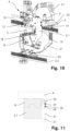
- the Fig. 10 shows an embodiment of a carrier 4.
- the carrier 4 has a first arm 14 with a first and a second end, with a first fastening area 17 for fastening an upper processing tool being arranged in the area of the first end.
- the carrier 4 also has a second arm 15 with a third and a fourth end, with a second fastening area 18 for a lower processing tool being arranged in the area of the third end.
- the second end of the first arm 14 and the fourth end of the second arm 15 are connected to one another via a connecting arm 16.
- the first arm 14 and the second arm 15 run parallel to one another and are arranged at a first distance from one another.
- the carrier 4 has a first carriage 19, which is arranged on the first arm 14, and a second carriage 20, which is arranged on the second arm 15.
- the carrier 4 can be mounted on two parallel linear guides, for example on the two linear guides 3.1, 3.2 of the device 1 according to Fig. 9 be arranged movably.
- Processing tools 5 for cutting and/or three-dimensional shaping of a strip material are preferably attached to the carrier 4 at the two fastening areas 17, 18.
- the carrier 4 also includes a cable guide 21, with which lines for control signals, electricity, compressed air or liquids can be guided from a fastening 22 for a drag chain from above or below to the first arm 14 or the second arm 15.
- the Fig. 11 shows the interaction of an embodiment of a positioning element 26 with a locking element 27.
- the positioning element 26 is arranged on a carrier 4, while the locking element 27 is on a linear guide, in which shown embodiment is attached to the first linear guide 3.1.
- the locking element 27 can also be attached to another component of the device 1, in particular the frame 2.
- the locking element 27 has a positioning pin 28, which can be brought from a retracted state (not shown) to the extended state shown, in particular via an actuator (not shown).
- the positioning pin 28 engages in a bore 29 of the positioning element 26.
- the bore 29 is cylindrical and has a conical opening 30 to enable automatic centering of the positioning pin 28 within the bore 29.
- the positioning pin 28 is moved linearly by means of an actuator 30, in particular a pneumatic actuator, and is biased into the extended state by means of a spring element (not shown) within the locking element 27.
Landscapes
- Engineering & Computer Science (AREA)
- Mechanical Engineering (AREA)
- Life Sciences & Earth Sciences (AREA)
- Forests & Forestry (AREA)
- Control Of Cutting Processes (AREA)
- Punching Or Piercing (AREA)
- Bearings For Parts Moving Linearly (AREA)
Priority Applications (3)
| Application Number | Priority Date | Filing Date | Title |
|---|---|---|---|
| EP22195424.1A EP4338905B1 (fr) | 2022-09-13 | 2022-09-13 | Dispositif et procédé de traitement d'un matériau |
| PCT/EP2023/072336 WO2024056290A1 (fr) | 2022-09-13 | 2023-08-11 | Dispositif et procédé d'usinage d'un matériau |
| CN202380064856.2A CN119894652A (zh) | 2022-09-13 | 2023-08-11 | 用于加工材料的装置及方法 |
Applications Claiming Priority (1)
| Application Number | Priority Date | Filing Date | Title |
|---|---|---|---|
| EP22195424.1A EP4338905B1 (fr) | 2022-09-13 | 2022-09-13 | Dispositif et procédé de traitement d'un matériau |
Publications (3)
| Publication Number | Publication Date |
|---|---|
| EP4338905A1 true EP4338905A1 (fr) | 2024-03-20 |
| EP4338905C0 EP4338905C0 (fr) | 2026-03-04 |
| EP4338905B1 EP4338905B1 (fr) | 2026-03-04 |
Family
ID=84044007
Family Applications (1)
| Application Number | Title | Priority Date | Filing Date |
|---|---|---|---|
| EP22195424.1A Active EP4338905B1 (fr) | 2022-09-13 | 2022-09-13 | Dispositif et procédé de traitement d'un matériau |
Country Status (3)
| Country | Link |
|---|---|
| EP (1) | EP4338905B1 (fr) |
| CN (1) | CN119894652A (fr) |
| WO (1) | WO2024056290A1 (fr) |
Citations (5)
| Publication number | Priority date | Publication date | Assignee | Title |
|---|---|---|---|---|
| US4604934A (en) * | 1985-05-08 | 1986-08-12 | Ppg Industries, Inc. | Carriage train precision linear positioning system |
| EP0997444A2 (fr) * | 1998-08-27 | 2000-05-03 | HEGLA Fahrzeug- u. Maschinenbau GmbH & Co. KG | Procédé et appareil pour positioner les têtes de travail d'une machine à multiples têtes de travail |
| US20060255083A1 (en) * | 2005-05-16 | 2006-11-16 | Bonaddio Robert M | On-line/off-line scoring bridge |
| EP3299136A1 (fr) * | 2016-09-21 | 2018-03-28 | Duplo Seiko Corporation | Refendeuse, dispositif de coupe de feuille et appareil de traitement de feuille |
| EP3689561A1 (fr) * | 2019-01-29 | 2020-08-05 | Multigraf AG | Dispositif d'usinage d'objets plans |
-
2022
- 2022-09-13 EP EP22195424.1A patent/EP4338905B1/fr active Active
-
2023
- 2023-08-11 CN CN202380064856.2A patent/CN119894652A/zh active Pending
- 2023-08-11 WO PCT/EP2023/072336 patent/WO2024056290A1/fr not_active Ceased
Patent Citations (5)
| Publication number | Priority date | Publication date | Assignee | Title |
|---|---|---|---|---|
| US4604934A (en) * | 1985-05-08 | 1986-08-12 | Ppg Industries, Inc. | Carriage train precision linear positioning system |
| EP0997444A2 (fr) * | 1998-08-27 | 2000-05-03 | HEGLA Fahrzeug- u. Maschinenbau GmbH & Co. KG | Procédé et appareil pour positioner les têtes de travail d'une machine à multiples têtes de travail |
| US20060255083A1 (en) * | 2005-05-16 | 2006-11-16 | Bonaddio Robert M | On-line/off-line scoring bridge |
| EP3299136A1 (fr) * | 2016-09-21 | 2018-03-28 | Duplo Seiko Corporation | Refendeuse, dispositif de coupe de feuille et appareil de traitement de feuille |
| EP3689561A1 (fr) * | 2019-01-29 | 2020-08-05 | Multigraf AG | Dispositif d'usinage d'objets plans |
Also Published As
| Publication number | Publication date |
|---|---|
| WO2024056290A1 (fr) | 2024-03-21 |
| EP4338905C0 (fr) | 2026-03-04 |
| EP4338905B1 (fr) | 2026-03-04 |
| CN119894652A (zh) | 2025-04-25 |
Similar Documents
| Publication | Publication Date | Title |
|---|---|---|
| EP2024111B1 (fr) | Dispositif et procédé pour produire des corps profilés | |
| EP0577068A1 (fr) | Machine de pliage | |
| CH657567A5 (de) | Revolver-stanze. | |
| EP2289643B1 (fr) | Dispositif pour le pliage de longues pièces usinées | |
| EP2923852B1 (fr) | Dispositif de formage de couvertures de livre | |
| DE2039697C3 (de) | Mehrstufige Formmaschine, insbesondere Mehrstufenpresse | |
| DE1935080A1 (de) | Verfahren zum automatischen Herstellen von Lamellen fuer Reifenformen und automatische Lamellenherstellmaschine | |
| DE102016116159A1 (de) | Verfahren und Vorrichtung zum Biegen von strangförmigen Werkstücken | |
| EP2532456B1 (fr) | Plieuse et outil de pliage | |
| DE4107709A1 (de) | Stanzpressenanordnung fuer stahltraeger | |
| DE202004020654U1 (de) | Schwenkmaschine, insbesondere für Blechprofilmaterialien | |
| EP0439680A2 (fr) | Procédé et dispositif pour transporter des objets le long d'une ligne de production | |
| EP4338905B1 (fr) | Dispositif et procédé de traitement d'un matériau | |
| DE68908562T2 (de) | System zur übertragung von werkstücken durch eine reihe von arbeitsstationen. | |
| EP4175776B1 (fr) | Dispositif pour produire un renfort en treillis métallique | |
| DE69703978T2 (de) | Vorrichtung zum regeln der grösse eines werkzeugmaschinen-blechhalters | |
| EP4338863B1 (fr) | Support pour outils d'usinage de matériau en bande et dispositif d'usinage de matériau en bande | |
| DE69511485T2 (de) | Blattfederbiegemaschine | |
| EP3199369B1 (fr) | Procédé destiné à préformer et à arrondir une tranche de livre | |
| WO2021013810A1 (fr) | Outil et procédé pour l'usinage de pièces en forme de plaques, en particulier de tôles | |
| AT406348B (de) | Mattentransporteur | |
| DE102024112761B3 (de) | Antriebsvorrichtung und Verfahren zur Beförderung zumindest eines Wagens entlang einer Förderbahn | |
| WO1993001011A1 (fr) | Procede pour le cintrage de precision de pieces precintrees en trois dimensions, ainsi que station de cintrage de precision associee | |
| DE102012018169A1 (de) | Vorrichtung zum Vorschieben und Biegen von Profilen aus Metall | |
| DE2935738A1 (de) | Verfahren und vorrichtung zum geradrichten eines metallstranges. |
Legal Events
| Date | Code | Title | Description |
|---|---|---|---|
| PUAI | Public reference made under article 153(3) epc to a published international application that has entered the european phase |
Free format text: ORIGINAL CODE: 0009012 |
|
| STAA | Information on the status of an ep patent application or granted ep patent |
Free format text: STATUS: THE APPLICATION HAS BEEN PUBLISHED |
|
| AK | Designated contracting states |
Kind code of ref document: A1 Designated state(s): AL AT BE BG CH CY CZ DE DK EE ES FI FR GB GR HR HU IE IS IT LI LT LU LV MC MK MT NL NO PL PT RO RS SE SI SK SM TR |
|
| STAA | Information on the status of an ep patent application or granted ep patent |
Free format text: STATUS: REQUEST FOR EXAMINATION WAS MADE |
|
| 17P | Request for examination filed |
Effective date: 20240911 |
|
| RBV | Designated contracting states (corrected) |
Designated state(s): AL AT BE BG CH CY CZ DE DK EE ES FI FR GB GR HR HU IE IS IT LI LT LU LV MC MK MT NL NO PL PT RO RS SE SI SK SM TR |
|
| GRAP | Despatch of communication of intention to grant a patent |
Free format text: ORIGINAL CODE: EPIDOSNIGR1 |
|
| STAA | Information on the status of an ep patent application or granted ep patent |
Free format text: STATUS: GRANT OF PATENT IS INTENDED |
|
| INTG | Intention to grant announced |
Effective date: 20250903 |
|
| GRAJ | Information related to disapproval of communication of intention to grant by the applicant or resumption of examination proceedings by the epo deleted |
Free format text: ORIGINAL CODE: EPIDOSDIGR1 |
|
| STAA | Information on the status of an ep patent application or granted ep patent |
Free format text: STATUS: REQUEST FOR EXAMINATION WAS MADE |
|
| INTC | Intention to grant announced (deleted) | ||
| GRAP | Despatch of communication of intention to grant a patent |
Free format text: ORIGINAL CODE: EPIDOSNIGR1 |
|
| STAA | Information on the status of an ep patent application or granted ep patent |
Free format text: STATUS: GRANT OF PATENT IS INTENDED |
|
| INTG | Intention to grant announced |
Effective date: 20251217 |
|
| GRAS | Grant fee paid |
Free format text: ORIGINAL CODE: EPIDOSNIGR3 |
|
| GRAA | (expected) grant |
Free format text: ORIGINAL CODE: 0009210 |
|
| STAA | Information on the status of an ep patent application or granted ep patent |
Free format text: STATUS: THE PATENT HAS BEEN GRANTED |
|
| AK | Designated contracting states |
Kind code of ref document: B1 Designated state(s): AL AT BE BG CH CY CZ DE DK EE ES FI FR GB GR HR HU IE IS IT LI LT LU LV MC MK MT NL NO PL PT RO RS SE SI SK SM TR |
|
| REG | Reference to a national code |
Ref country code: CH Ref legal event code: F10 Free format text: ST27 STATUS EVENT CODE: U-0-0-F10-F00 (AS PROVIDED BY THE NATIONAL OFFICE) Effective date: 20260304 Ref country code: GB Ref legal event code: FG4D Free format text: NOT ENGLISH |
|
| REG | Reference to a national code |
Ref country code: IE Ref legal event code: FG4D Free format text: LANGUAGE OF EP DOCUMENT: GERMAN |
|
| U01 | Request for unitary effect filed |
Effective date: 20260306 |
|
| U07 | Unitary effect registered |
Designated state(s): AT BE BG DE DK EE FI FR IT LT LU LV MT NL PT RO SE SI Effective date: 20260311 |
|
| U1N | Appointed representative for the unitary patent procedure changed after the registration of the unitary effect |
Representative=s name: KELLER SCHNEIDERPATENT- UND MARKENANWAELTE AG; CH |