EP4338936A1 - Procédé d'impression 3d - Google Patents
Procédé d'impression 3d Download PDFInfo
- Publication number
- EP4338936A1 EP4338936A1 EP22195785.5A EP22195785A EP4338936A1 EP 4338936 A1 EP4338936 A1 EP 4338936A1 EP 22195785 A EP22195785 A EP 22195785A EP 4338936 A1 EP4338936 A1 EP 4338936A1
- Authority
- EP
- European Patent Office
- Prior art keywords
- projection
- container
- projection device
- images
- projection images
- Prior art date
- Legal status (The legal status is an assumption and is not a legal conclusion. Google has not performed a legal analysis and makes no representation as to the accuracy of the status listed.)
- Granted
Links
Images


Classifications
-
- G—PHYSICS
- G05—CONTROLLING; REGULATING
- G05B—CONTROL OR REGULATING SYSTEMS IN GENERAL; FUNCTIONAL ELEMENTS OF SUCH SYSTEMS; MONITORING OR TESTING ARRANGEMENTS FOR SUCH SYSTEMS OR ELEMENTS
- G05B19/00—Program-control systems
- G05B19/02—Program-control systems electric
- G05B19/18—Numerical control [NC], i.e. automatically operating machines, in particular machine tools, e.g. in a manufacturing environment, so as to execute positioning, movement or co-ordinated operations by means of program data in numerical form
- G05B19/4097—Numerical control [NC], i.e. automatically operating machines, in particular machine tools, e.g. in a manufacturing environment, so as to execute positioning, movement or co-ordinated operations by means of program data in numerical form characterised by using design data to control NC machines, e.g. CAD/CAM
- G05B19/4099—Surface or curve machining, making three-dimensional [3D] objects, e.g. desktop manufacturing
-
- B—PERFORMING OPERATIONS; TRANSPORTING
- B29—WORKING OF PLASTICS; WORKING OF SUBSTANCES IN A PLASTIC STATE IN GENERAL
- B29C—SHAPING OR JOINING OF PLASTICS; SHAPING OF MATERIAL IN A PLASTIC STATE, NOT OTHERWISE PROVIDED FOR; AFTER-TREATMENT OF THE SHAPED PRODUCTS, e.g. REPAIRING
- B29C64/00—Additive manufacturing, i.e. manufacturing of three-dimensional [3D] objects by additive deposition, additive agglomeration or additive layering, e.g. by 3D printing, stereolithography or selective laser sintering
- B29C64/10—Processes of additive manufacturing
- B29C64/106—Processes of additive manufacturing using only liquids or viscous materials, e.g. depositing a continuous bead of viscous material
- B29C64/124—Processes of additive manufacturing using only liquids or viscous materials, e.g. depositing a continuous bead of viscous material using layers of liquid which are selectively solidified
-
- B—PERFORMING OPERATIONS; TRANSPORTING
- B29—WORKING OF PLASTICS; WORKING OF SUBSTANCES IN A PLASTIC STATE IN GENERAL
- B29C—SHAPING OR JOINING OF PLASTICS; SHAPING OF MATERIAL IN A PLASTIC STATE, NOT OTHERWISE PROVIDED FOR; AFTER-TREATMENT OF THE SHAPED PRODUCTS, e.g. REPAIRING
- B29C64/00—Additive manufacturing, i.e. manufacturing of three-dimensional [3D] objects by additive deposition, additive agglomeration or additive layering, e.g. by 3D printing, stereolithography or selective laser sintering
- B29C64/10—Processes of additive manufacturing
- B29C64/106—Processes of additive manufacturing using only liquids or viscous materials, e.g. depositing a continuous bead of viscous material
- B29C64/124—Processes of additive manufacturing using only liquids or viscous materials, e.g. depositing a continuous bead of viscous material using layers of liquid which are selectively solidified
- B29C64/129—Processes of additive manufacturing using only liquids or viscous materials, e.g. depositing a continuous bead of viscous material using layers of liquid which are selectively solidified characterised by the energy source therefor, e.g. by global irradiation combined with a mask
-
- B—PERFORMING OPERATIONS; TRANSPORTING
- B29—WORKING OF PLASTICS; WORKING OF SUBSTANCES IN A PLASTIC STATE IN GENERAL
- B29C—SHAPING OR JOINING OF PLASTICS; SHAPING OF MATERIAL IN A PLASTIC STATE, NOT OTHERWISE PROVIDED FOR; AFTER-TREATMENT OF THE SHAPED PRODUCTS, e.g. REPAIRING
- B29C64/00—Additive manufacturing, i.e. manufacturing of three-dimensional [3D] objects by additive deposition, additive agglomeration or additive layering, e.g. by 3D printing, stereolithography or selective laser sintering
- B29C64/20—Apparatus for additive manufacturing; Details thereof or accessories therefor
- B29C64/264—Arrangements for irradiation
-
- B—PERFORMING OPERATIONS; TRANSPORTING
- B29—WORKING OF PLASTICS; WORKING OF SUBSTANCES IN A PLASTIC STATE IN GENERAL
- B29C—SHAPING OR JOINING OF PLASTICS; SHAPING OF MATERIAL IN A PLASTIC STATE, NOT OTHERWISE PROVIDED FOR; AFTER-TREATMENT OF THE SHAPED PRODUCTS, e.g. REPAIRING
- B29C64/00—Additive manufacturing, i.e. manufacturing of three-dimensional [3D] objects by additive deposition, additive agglomeration or additive layering, e.g. by 3D printing, stereolithography or selective laser sintering
- B29C64/30—Auxiliary operations or equipment
- B29C64/386—Data acquisition or data processing for additive manufacturing
- B29C64/393—Data acquisition or data processing for additive manufacturing for controlling or regulating additive manufacturing processes
-
- B—PERFORMING OPERATIONS; TRANSPORTING
- B33—ADDITIVE MANUFACTURING TECHNOLOGY
- B33Y—ADDITIVE MANUFACTURING, i.e. MANUFACTURING OF THREE-DIMENSIONAL [3D] OBJECTS BY ADDITIVE DEPOSITION, ADDITIVE AGGLOMERATION OR ADDITIVE LAYERING, e.g. BY 3D PRINTING, STEREOLITHOGRAPHY OR SELECTIVE LASER SINTERING
- B33Y10/00—Processes of additive manufacturing
-
- B—PERFORMING OPERATIONS; TRANSPORTING
- B33—ADDITIVE MANUFACTURING TECHNOLOGY
- B33Y—ADDITIVE MANUFACTURING, i.e. MANUFACTURING OF THREE-DIMENSIONAL [3D] OBJECTS BY ADDITIVE DEPOSITION, ADDITIVE AGGLOMERATION OR ADDITIVE LAYERING, e.g. BY 3D PRINTING, STEREOLITHOGRAPHY OR SELECTIVE LASER SINTERING
- B33Y30/00—Apparatus for additive manufacturing; Details thereof or accessories therefor
-
- B—PERFORMING OPERATIONS; TRANSPORTING
- B33—ADDITIVE MANUFACTURING TECHNOLOGY
- B33Y—ADDITIVE MANUFACTURING, i.e. MANUFACTURING OF THREE-DIMENSIONAL [3D] OBJECTS BY ADDITIVE DEPOSITION, ADDITIVE AGGLOMERATION OR ADDITIVE LAYERING, e.g. BY 3D PRINTING, STEREOLITHOGRAPHY OR SELECTIVE LASER SINTERING
- B33Y50/00—Data acquisition or data processing for additive manufacturing
-
- B—PERFORMING OPERATIONS; TRANSPORTING
- B33—ADDITIVE MANUFACTURING TECHNOLOGY
- B33Y—ADDITIVE MANUFACTURING, i.e. MANUFACTURING OF THREE-DIMENSIONAL [3D] OBJECTS BY ADDITIVE DEPOSITION, ADDITIVE AGGLOMERATION OR ADDITIVE LAYERING, e.g. BY 3D PRINTING, STEREOLITHOGRAPHY OR SELECTIVE LASER SINTERING
- B33Y50/00—Data acquisition or data processing for additive manufacturing
- B33Y50/02—Data acquisition or data processing for additive manufacturing for controlling or regulating additive manufacturing processes
-
- G—PHYSICS
- G05—CONTROLLING; REGULATING
- G05B—CONTROL OR REGULATING SYSTEMS IN GENERAL; FUNCTIONAL ELEMENTS OF SUCH SYSTEMS; MONITORING OR TESTING ARRANGEMENTS FOR SUCH SYSTEMS OR ELEMENTS
- G05B2219/00—Program-control systems
- G05B2219/30—Nc systems
- G05B2219/35—Nc in input of data, input till input file format
- G05B2219/35134—3-D cad-cam
Definitions
- the size or extent of the three-dimensional object to be produced is limited by the depth of field range of the projection devices, since the light intensity with which the projection images are imaged must be sufficiently high, but this is only the case a rather large aperture opening - and the resulting narrow depth of field - can be achieved.
- the aperture of the at least one projection device is therefore usually fixed in the prior art and is due to an interaction between the light intensity of the light source of the projection device and the desired depth of field or depth of field. Due to the fixed aperture, the depth of field range is also fixed and naturally limited.
- the depth of field range depends quadratically on the size of the pixels, with orders of magnitude of 100 mm for 100 ⁇ m pixel size, 1 mm for 10 ⁇ m pixel size and 10 ⁇ m for 1 ⁇ m pixel size being typical, i.e. the more precise you want to print (i.e. smaller pixels). ), the more the limiting depth of field has an impact and prevents the production of a larger object.
- the object to be manufactured necessarily has a maximum size or extent of can usually be a few 10 mm, depending on the implementation up to a single or double depth of field.
- step b) if in an angular position the extent of the three-dimensional object to be produced along the radiation direction of the at least one projection device in this angular position is at least twice larger than the specified depth of field range, the focal plane is shifted in this way relative to the container , so that at least half of the extent of the three-dimensional object to be produced along the respective radiation direction in the respective angular position is covered by the depth of field range.
- the light intensity is also proportional to the summed virtual object material, so that those locations that have a larger sum of virtual object material compared to others have a higher light intensity when imaging.
- the projection images can preferably be obtained by a Radon transformation.
- step b) can optionally be repeated until the object to be produced has hardened in the light-sensitive substance.
- the light-sensitive substance is a light-sensitive resin, for example made of a photopolymer and a photoinitiator.
- a photopolymer for example, gelatin methacrylate (gelMA) dissolved in phosphate-buffered saline (PBS); bisphenol A glycerolate diacrylate (BPAGDA); Poly(ethylene glycol) diacrylate (PEGDA) or pentaerythritol tetraacrylate (PETA) can be used.
- gelMA gelatin methacrylate
- PBS phosphate-buffered saline
- BPAGDA bisphenol A glycerolate diacrylate
- PEGDA Poly(ethylene glycol) diacrylate
- PETA pentaerythritol tetraacrylate
- a photoinitiator for example, lithium phenyl 2,4,6-trimethylbenzoyl phosphinate (LAP); Camphorquinone (CQ), with co-initiator ethyl 4-dimethylaminobenzoate (EDAB); Tris(2,2-bipyridyl)dichlororuthenium(II) hexahydrate (Ru) and sodium persulfate (SPS); 3,4-Epoxycyclohexylmethyl 3,4-Epoxycyclohexanecarboxylate (EEC); Phenylbis(2,4,6-trimethylbenzoyl)phosphine oxide or bis( ⁇ 5-2,4-cylcopentadien-1-yl)-bis(2,6-difluoro-3-(1H-pyrrol-1-yl)-phenyl)titanium (Brand name: Irgacure 784, BASF) can be used.
- LAP lithium phenyl 2,4,6
- step a it can be provided that exactly one projection device is provided in step a).
- the container in order to image the projection images by the at least one projection device in the respective angular positions, the container is rotated about the container axis.
- the at least one projection device in order to image the projection images by the at least one projection device in the respective angular positions, is rotated about the container axis.
- the displacement of the focal plane in the respective angular positions takes place by moving the container relative to the at least one projection device, in particular linearly moved along the radiation direction of the at least one projection device.
- the focal plane is moved in the respective angular positions by moving the at least one projection device relative to the container, in particular linearly moved along the radiation direction of the at least one projection device.
- the focal plane is shifted in the respective angular positions by adjusting a focus or a focal length of the at least one projection device.
- the focal plane is shifted by a spiral movement of the container and/or the projection device.
- the different angular positions in which the projection images are imaged are spaced from one another by 0.5° to 5°.
- the projection directions of the projection images run around the defined object axis at defined equal distances from one another, preferably at distances of 0.5° to 5°, in particular 0.5°.
- step b) the imaging of the projection images in the different projection directions into the container takes place continuously or step by step.
- the figures show a schematic sequence of a volumetric 3D printing process for producing a three-dimensional object 50 starting from a three-dimensional template object 100, which is formed from a virtual object material and in Fig. 1 is shown in a perspective view.
- the method includes providing at least one memory, projection images 200 of the template object 100 being stored in the at least one memory.
- the projection images 200 are two-dimensional light distributions of pixels in rows and columns, which projection images 200 correspond to projections of the template object 100 in different projection directions PR1 - PR8 around a fixed object axis OA , the projection directions PR1 - PR8 of the projection -Images 200 run orthogonally to the specified object axis OA .
- Fig. 2A shows the template object 100 in a view from above, with projection images 200 being present around the defined object axis OA at equal angular distances of 45°.
- the angular distance between the projection directions PR1 - PR8 is 45° in the example shown merely for simplified representation and can preferably also be 0.5° to 5°, in particular 0.5°.
- the brightness of a pixel of a projection image 200 corresponds to the summed virtual object material of the template object 100, starting from the pixel, along the projection direction PR1 - PR8 of the corresponding projection image 200 in such a way that the brightness of a pixel is proportional to its summed virtual object material.
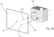
- Fig. 2B shows an exemplary projection image 200, with two pixels 211, 212 shown as examples.
- the corresponding projection image and projection direction are also in Fig. 2A drawn.
- the virtual object material is added up, as already described.
- the sum of the virtual object material starting from the pixel with reference number 211 is greater than the sum starting from the pixel with reference number 212.
- the pixel with reference number 211 is therefore shown darker in the projection image in the examples shown than the pixel with reference number 212 .It should be noted that the representation can also be done the other way around, that is, those pixels with a higher sum of the summed virtual object material are brighter than those whose sum is smaller in comparison.
- Radon transformation can also be used as a preferred method for creating the individual projection images 200 .
- a projection device 300 is provided, which is set up to project the projection images 200 of the template object 100 in the direction of a radiation direction to be depicted sharply.
- the light intensity is also proportional to the summed virtual object material, so that those locations or pixels that have a larger sum of virtual object material compared to others have a higher light intensity when imaging.
- That pixel with the reference number 211 has a higher light intensity than the pixel with the reference number 212.
- a container 400 which contains a photosensitive substance 410 , the photosensitive substance 410 being set up in areas in which a Light intensity threshold is exceeded to cure. This light intensity threshold is reached or exceeded due to the irradiation of light over a certain period of time - depending on the choice of photosensitive substance.
- step b) of the volumetric 3D printing process shows a step b) of the volumetric 3D printing process, where the Figures 3A to 3H as a sequence starting with Fig. 3A you can see.
- step b) the projection images 200 are imaged into the photosensitive substance 410 located in the container 400 by means of the projection device 300 , so that the light intensity threshold of the light-sensitive substance is exceeded in the areas which correspond to the three-dimensional object 50 to be produced.
- the individual projection images 200 will each be imaged in different angular positions WP1 - WP8 about a fixed container axis BA into the photosensitive substance 410 , the radiation direction X of the at least one projection device 300 being in an angular position WP1 - WP8 of the projection direction PR1 - PR8 of in the angular position WP1 - WP8 corresponds to the projection image 200 of the template object 100 .
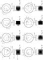
- 3A to 3H as well as 4A to 4C show a simplified schematic sequence of the volumetric 3D printing method according to the invention for producing an object 50 starting from the virtual template object 100 using an example.
- FIG. 3A to 3H The container 400 in which the light-sensitive substance, for example a resin, is arranged is shown in each case, the container 400 being rotatable about a container axis BA . Furthermore, a projection device 300 is shown in each of the figures, which displays the different projection images from the previous one in the direction of a radiation direction X Fig. 2A depicts. In Fig. 3A that projection image 200 is imaged, which corresponds to the projection direction PR1 , the container 400 with the light-sensitive substance located therein being in a first angular position WP1 relative to the projection device 300 .
- the container 400 with the light-sensitive substance located therein being in a first angular position WP1 relative to the projection device 300 .
- a next step - can be seen in Fig. 3B - the container 400 together with the resin is rotated about the container axis BA relative to the projection device 300 by an angle W and is in a second angular position WP2 relative to the projection device 300.
- the projection device 300 images the projection image 200 into the light-sensitive substance, which corresponds to the projection direction PR2 .
- the radiation direction of the projection device 300 in a certain angular position WP1 - WP8 corresponds to the respective projection direction PR1 - PR8 of the projection image 200 of the template object 100 depicted in the angular position.
- the projection device 300 can also be rotated relative to the container 400 about the container axis BA .
- step b) if in an angular position WP1 - WP8 the extent of the three-dimensional object 50 to be produced along the radiation direction shifted to the container 400 , so that at least half of the extent of the three-dimensional object 50 to be produced along the respective radiation direction X in the respective angular position WP1 - WP8 is covered by the depth of field range ST .
- Half of the expansion in an angular position is sufficient because the "other" half can be caused to harden when the angular position is rotated by 180°.
- FIG. 4A An example is in 4A to 4C starting from the first angular position WP1 in Fig. 3A shown that the extent of the three-dimensional object 50 to be produced along the radiation direction X of the projection device 300 is larger than the depth of field range ST of the focal plane F.
- the depth of field range ST is shifted to the container 400 by means of a linear relative displacement of the projection device 300 along the radiation direction PR1 corresponds to the light-sensitive substance 410 being imaged.
- the displacement of the focal plane F in the respective angular positions WP1 - WP8 can also be done by moving the container 400 relative to the projection device 300 , in particular by moving it linearly along the radiation direction X of the projection device 300.
- the focal plane F can be moved in the respective angular positions WP1 - WP8 by adjusting a focus or the focal length of the projection device 300 .
- the three-dimensional object 50 After imaging the projection image 200 in Fig. 3H and the associated shifting of the depth of field ST - i.e. a complete pass - the three-dimensional object 50 should be hardened. In the event that this is not the case, the passage in 3A to 3H (including the respective shifting of the depth of field range ST) can be repeated as often as desired.
Landscapes
- Engineering & Computer Science (AREA)
- Chemical & Material Sciences (AREA)
- Materials Engineering (AREA)
- Manufacturing & Machinery (AREA)
- Physics & Mathematics (AREA)
- Mechanical Engineering (AREA)
- Optics & Photonics (AREA)
- Human Computer Interaction (AREA)
- General Physics & Mathematics (AREA)
- Automation & Control Theory (AREA)
- Health & Medical Sciences (AREA)
- Toxicology (AREA)
Priority Applications (2)
| Application Number | Priority Date | Filing Date | Title |
|---|---|---|---|
| EP22195785.5A EP4338936B1 (fr) | 2022-09-15 | 2022-09-15 | Procédé d'impression 3d |
| US18/238,633 US12366843B2 (en) | 2022-09-15 | 2023-08-28 | 3D printing method |
Applications Claiming Priority (1)
| Application Number | Priority Date | Filing Date | Title |
|---|---|---|---|
| EP22195785.5A EP4338936B1 (fr) | 2022-09-15 | 2022-09-15 | Procédé d'impression 3d |
Publications (3)
| Publication Number | Publication Date |
|---|---|
| EP4338936A1 true EP4338936A1 (fr) | 2024-03-20 |
| EP4338936C0 EP4338936C0 (fr) | 2025-06-11 |
| EP4338936B1 EP4338936B1 (fr) | 2025-06-11 |
Family
ID=83355473
Family Applications (1)
| Application Number | Title | Priority Date | Filing Date |
|---|---|---|---|
| EP22195785.5A Active EP4338936B1 (fr) | 2022-09-15 | 2022-09-15 | Procédé d'impression 3d |
Country Status (2)
| Country | Link |
|---|---|
| US (1) | US12366843B2 (fr) |
| EP (1) | EP4338936B1 (fr) |
Citations (2)
| Publication number | Priority date | Publication date | Assignee | Title |
|---|---|---|---|---|
| WO2020232083A1 (fr) * | 2019-05-13 | 2020-11-19 | Lawrence Livermore National Security, Llc | Résines photodurcissables pour la fabrication additive volumétrique |
| WO2022171704A1 (fr) * | 2021-02-09 | 2022-08-18 | Universite Claude Bernard Lyon 1 | Procédé d'impression d'un objet 3d dans une composition photoréactive, et imprimante adaptée pour la mise en oeuvre du procédé. |
Family Cites Families (3)
| Publication number | Priority date | Publication date | Assignee | Title |
|---|---|---|---|---|
| CN104999666B (zh) * | 2014-04-18 | 2017-08-11 | 台达电子工业股份有限公司 | 三维扫描打印装置 |
| CN118003625A (zh) * | 2019-01-24 | 2024-05-10 | 沃尔特·沃伊特 | 用于超高吞吐量增材制造的系统、方法及材料 |
| US20220347929A1 (en) * | 2019-06-21 | 2022-11-03 | Ecole Polytechnique Federale De Lausanne | System and method of using feedback for correcting three dimensional objects in volumetric tomographic printers |
-
2022
- 2022-09-15 EP EP22195785.5A patent/EP4338936B1/fr active Active
-
2023
- 2023-08-28 US US18/238,633 patent/US12366843B2/en active Active
Patent Citations (2)
| Publication number | Priority date | Publication date | Assignee | Title |
|---|---|---|---|---|
| WO2020232083A1 (fr) * | 2019-05-13 | 2020-11-19 | Lawrence Livermore National Security, Llc | Résines photodurcissables pour la fabrication additive volumétrique |
| WO2022171704A1 (fr) * | 2021-02-09 | 2022-08-18 | Universite Claude Bernard Lyon 1 | Procédé d'impression d'un objet 3d dans une composition photoréactive, et imprimante adaptée pour la mise en oeuvre du procédé. |
Also Published As
| Publication number | Publication date |
|---|---|
| US20240094703A1 (en) | 2024-03-21 |
| EP4338936C0 (fr) | 2025-06-11 |
| EP4338936B1 (fr) | 2025-06-11 |
| US12366843B2 (en) | 2025-07-22 |
Similar Documents
| Publication | Publication Date | Title |
|---|---|---|
| DE102006019964B4 (de) | Vorrichtung und Verfahren zur Herstellung eines dreidimensionalen Objekts mittels Maskenbelichtung | |
| EP2156239B1 (fr) | Procédé permettant d'aligner un élément optique sur un écran | |
| DE69508414T2 (de) | Markierungssystem für kleidungsstücke mit einer rechnergestützten ausrichtung von symmetrischen stoffmustern | |
| DE102017110241A1 (de) | Verfahren zum Erzeugen einer 3D-Struktur mittels Laserlithographie sowie Computerprogrammprodukt | |
| WO1995031795A2 (fr) | Procede de production d'images en relief | |
| DE102015208852A1 (de) | Verfahren zum Herstellen einer dreidimensionalen Struktur | |
| EP3569147A1 (fr) | Procédé et appareil de détermination d'un étalonnage géométrique pour un dispositif d'imagerie ainsi que procédé de détermination de données d'attribution pour étalonnage géométrique | |
| EP0954618B1 (fr) | Methode de generation des planstechniques courbes ou contours | |
| EP4338936B1 (fr) | Procédé d'impression 3d | |
| DE10307373A1 (de) | Verfahren und Vorrichtung zur Untersuchung von Halbleiterwafern unter Berücksichtigung des Die-/SAW-Designs | |
| EP3247552A1 (fr) | Procédé d'exposition à l'action de la lumière d'une zone tridimensionnelle | |
| DE102018212104A1 (de) | Verfahren und Anordnung zum optischen Erfassen eines Objekts mittels Lichtmusterprojektion | |
| DE102018128184A1 (de) | Verfahren, Vorrichtung, Computerprogramm und Computerprogrammprodukt zur Erzeugung eines gelabelten Bildes | |
| EP2642749B1 (fr) | Dispositif et procédé d'optimisation de la détermination de zones de capture | |
| WO2023284922A1 (fr) | Procédé et système pour déterminer la position spatiale d'un objet | |
| EP4477995B1 (fr) | Procédé et dispositif de mesure sans contact d'objets | |
| EP4125040A1 (fr) | Détermination de positions optimisées de mesure dans la tomographie assistée par ordinateur | |
| DE102006042386B4 (de) | Verfahren und Vorrichtung zur Darstellung von Bildern | |
| DE102015218829A1 (de) | Bilderzeugungsvorrichtung und Verfahren zur Herstellung eines Arrays bildgebender Elemente | |
| DE4328915C1 (de) | Verfahren zur Extraktion von Merkmalen linienhafter Strukturen in digitalen Bildern | |
| DE4000021A1 (de) | Verfahren und vorrichtung zur darstellung von kurven in einem zweidimensionalen raster von bildelementen | |
| DE102012218854A1 (de) | Verfahren und Vorrichtung zur Kompression von Bilddaten | |
| DE1934051C3 (de) | Verfahren und Einrichtung zum Erzeugen eines ausgefüllten Bildmusters | |
| DE102023111938A1 (de) | Verfahren zur kontaktlosen erfassung von biometriedaten von biometrischen merkmalen mittels einer erfassungsvorrichtung und vorrichtung zur kontaktlosen erfassung von biometriedaten von biometrischen merkmalen | |
| DE252995C (fr) |
Legal Events
| Date | Code | Title | Description |
|---|---|---|---|
| PUAI | Public reference made under article 153(3) epc to a published international application that has entered the european phase |
Free format text: ORIGINAL CODE: 0009012 |
|
| STAA | Information on the status of an ep patent application or granted ep patent |
Free format text: STATUS: THE APPLICATION HAS BEEN PUBLISHED |
|
| AK | Designated contracting states |
Kind code of ref document: A1 Designated state(s): AL AT BE BG CH CY CZ DE DK EE ES FI FR GB GR HR HU IE IS IT LI LT LU LV MC MK MT NL NO PL PT RO RS SE SI SK SM TR |
|
| STAA | Information on the status of an ep patent application or granted ep patent |
Free format text: STATUS: REQUEST FOR EXAMINATION WAS MADE |
|
| 17P | Request for examination filed |
Effective date: 20240919 |
|
| RBV | Designated contracting states (corrected) |
Designated state(s): AL AT BE BG CH CY CZ DE DK EE ES FI FR GB GR HR HU IE IS IT LI LT LU LV MC MK MT NL NO PL PT RO RS SE SI SK SM TR |
|
| GRAP | Despatch of communication of intention to grant a patent |
Free format text: ORIGINAL CODE: EPIDOSNIGR1 |
|
| STAA | Information on the status of an ep patent application or granted ep patent |
Free format text: STATUS: GRANT OF PATENT IS INTENDED |
|
| INTG | Intention to grant announced |
Effective date: 20250131 |
|
| GRAS | Grant fee paid |
Free format text: ORIGINAL CODE: EPIDOSNIGR3 |
|
| GRAA | (expected) grant |
Free format text: ORIGINAL CODE: 0009210 |
|
| STAA | Information on the status of an ep patent application or granted ep patent |
Free format text: STATUS: THE PATENT HAS BEEN GRANTED |
|
| AK | Designated contracting states |
Kind code of ref document: B1 Designated state(s): AL AT BE BG CH CY CZ DE DK EE ES FI FR GB GR HR HU IE IS IT LI LT LU LV MC MK MT NL NO PL PT RO RS SE SI SK SM TR |
|
| REG | Reference to a national code |
Ref country code: GB Ref legal event code: FG4D Free format text: NOT ENGLISH |
|
| REG | Reference to a national code |
Ref country code: CH Ref legal event code: EP |
|
| REG | Reference to a national code |
Ref country code: DE Ref legal event code: R096 Ref document number: 502022004224 Country of ref document: DE |
|
| REG | Reference to a national code |
Ref country code: IE Ref legal event code: FG4D Free format text: LANGUAGE OF EP DOCUMENT: GERMAN |
|
| U01 | Request for unitary effect filed |
Effective date: 20250709 |
|
| U07 | Unitary effect registered |
Designated state(s): AT BE BG DE DK EE FI FR IT LT LU LV MT NL PT RO SE SI Effective date: 20250715 |
|
| PG25 | Lapsed in a contracting state [announced via postgrant information from national office to epo] |
Ref country code: ES Free format text: LAPSE BECAUSE OF FAILURE TO SUBMIT A TRANSLATION OF THE DESCRIPTION OR TO PAY THE FEE WITHIN THE PRESCRIBED TIME-LIMIT Effective date: 20250611 |
|
| PG25 | Lapsed in a contracting state [announced via postgrant information from national office to epo] |
Ref country code: GR Free format text: LAPSE BECAUSE OF FAILURE TO SUBMIT A TRANSLATION OF THE DESCRIPTION OR TO PAY THE FEE WITHIN THE PRESCRIBED TIME-LIMIT Effective date: 20250912 Ref country code: NO Free format text: LAPSE BECAUSE OF FAILURE TO SUBMIT A TRANSLATION OF THE DESCRIPTION OR TO PAY THE FEE WITHIN THE PRESCRIBED TIME-LIMIT Effective date: 20250911 |
|
| PG25 | Lapsed in a contracting state [announced via postgrant information from national office to epo] |
Ref country code: HR Free format text: LAPSE BECAUSE OF FAILURE TO SUBMIT A TRANSLATION OF THE DESCRIPTION OR TO PAY THE FEE WITHIN THE PRESCRIBED TIME-LIMIT Effective date: 20250611 |
|
| PG25 | Lapsed in a contracting state [announced via postgrant information from national office to epo] |
Ref country code: RS Free format text: LAPSE BECAUSE OF FAILURE TO SUBMIT A TRANSLATION OF THE DESCRIPTION OR TO PAY THE FEE WITHIN THE PRESCRIBED TIME-LIMIT Effective date: 20250911 |
|
| U20 | Renewal fee for the european patent with unitary effect paid |
Year of fee payment: 4 Effective date: 20250930 |
|
| PG25 | Lapsed in a contracting state [announced via postgrant information from national office to epo] |
Ref country code: IS Free format text: LAPSE BECAUSE OF FAILURE TO SUBMIT A TRANSLATION OF THE DESCRIPTION OR TO PAY THE FEE WITHIN THE PRESCRIBED TIME-LIMIT Effective date: 20251011 |
|
| PG25 | Lapsed in a contracting state [announced via postgrant information from national office to epo] |
Ref country code: SM Free format text: LAPSE BECAUSE OF FAILURE TO SUBMIT A TRANSLATION OF THE DESCRIPTION OR TO PAY THE FEE WITHIN THE PRESCRIBED TIME-LIMIT Effective date: 20250611 |
|
| PG25 | Lapsed in a contracting state [announced via postgrant information from national office to epo] |
Ref country code: CZ Free format text: LAPSE BECAUSE OF FAILURE TO SUBMIT A TRANSLATION OF THE DESCRIPTION OR TO PAY THE FEE WITHIN THE PRESCRIBED TIME-LIMIT Effective date: 20250611 |
|
| PG25 | Lapsed in a contracting state [announced via postgrant information from national office to epo] |
Ref country code: PL Free format text: LAPSE BECAUSE OF FAILURE TO SUBMIT A TRANSLATION OF THE DESCRIPTION OR TO PAY THE FEE WITHIN THE PRESCRIBED TIME-LIMIT Effective date: 20250611 |
|
| PG25 | Lapsed in a contracting state [announced via postgrant information from national office to epo] |
Ref country code: SK Free format text: LAPSE BECAUSE OF FAILURE TO SUBMIT A TRANSLATION OF THE DESCRIPTION OR TO PAY THE FEE WITHIN THE PRESCRIBED TIME-LIMIT Effective date: 20250611 |
|
| PGFP | Annual fee paid to national office [announced via postgrant information from national office to epo] |
Ref country code: IE Payment date: 20260126 Year of fee payment: 4 |
|
| PLBE | No opposition filed within time limit |
Free format text: ORIGINAL CODE: 0009261 |
|
| STAA | Information on the status of an ep patent application or granted ep patent |
Free format text: STATUS: NO OPPOSITION FILED WITHIN TIME LIMIT |
|
| REG | Reference to a national code |
Ref country code: CH Ref legal event code: L10 Free format text: ST27 STATUS EVENT CODE: U-0-0-L10-L00 (AS PROVIDED BY THE NATIONAL OFFICE) Effective date: 20260423 |