EP4338939A2 - Machine de fusion de tuyaux - Google Patents
Machine de fusion de tuyaux Download PDFInfo
- Publication number
- EP4338939A2 EP4338939A2 EP24154672.0A EP24154672A EP4338939A2 EP 4338939 A2 EP4338939 A2 EP 4338939A2 EP 24154672 A EP24154672 A EP 24154672A EP 4338939 A2 EP4338939 A2 EP 4338939A2
- Authority
- EP
- European Patent Office
- Prior art keywords
- carriage
- frame
- guide rails
- fusion
- jaw
- Prior art date
- Legal status (The legal status is an assumption and is not a legal conclusion. Google has not performed a legal analysis and makes no representation as to the accuracy of the status listed.)
- Pending
Links
Images




Classifications
-
- B—PERFORMING OPERATIONS; TRANSPORTING
- B29—WORKING OF PLASTICS; WORKING OF SUBSTANCES IN A PLASTIC STATE IN GENERAL
- B29C—SHAPING OR JOINING OF PLASTICS; SHAPING OF MATERIAL IN A PLASTIC STATE, NOT OTHERWISE PROVIDED FOR; AFTER-TREATMENT OF THE SHAPED PRODUCTS, e.g. REPAIRING
- B29C65/00—Joining or sealing of preformed parts, e.g. welding of plastics materials; Apparatus therefor
- B29C65/02—Joining or sealing of preformed parts, e.g. welding of plastics materials; Apparatus therefor by heating, with or without pressure
-
- B—PERFORMING OPERATIONS; TRANSPORTING
- B29—WORKING OF PLASTICS; WORKING OF SUBSTANCES IN A PLASTIC STATE IN GENERAL
- B29C—SHAPING OR JOINING OF PLASTICS; SHAPING OF MATERIAL IN A PLASTIC STATE, NOT OTHERWISE PROVIDED FOR; AFTER-TREATMENT OF THE SHAPED PRODUCTS, e.g. REPAIRING
- B29C66/00—General aspects of processes or apparatus for joining preformed parts
- B29C66/90—Measuring or controlling the joining process
- B29C66/92—Measuring or controlling the joining process by measuring or controlling the pressure, the force, the mechanical power or the displacement of the joining tools
- B29C66/922—Measuring or controlling the joining process by measuring or controlling the pressure, the force, the mechanical power or the displacement of the joining tools by measuring the pressure, the force, the mechanical power or the displacement of the joining tools
- B29C66/9221—Measuring or controlling the joining process by measuring or controlling the pressure, the force, the mechanical power or the displacement of the joining tools by measuring the pressure, the force, the mechanical power or the displacement of the joining tools by measuring the pressure, the force or the mechanical power
- B29C66/92211—Measuring or controlling the joining process by measuring or controlling the pressure, the force, the mechanical power or the displacement of the joining tools by measuring the pressure, the force, the mechanical power or the displacement of the joining tools by measuring the pressure, the force or the mechanical power with special measurement means or methods
-
- B—PERFORMING OPERATIONS; TRANSPORTING
- B29—WORKING OF PLASTICS; WORKING OF SUBSTANCES IN A PLASTIC STATE IN GENERAL
- B29C—SHAPING OR JOINING OF PLASTICS; SHAPING OF MATERIAL IN A PLASTIC STATE, NOT OTHERWISE PROVIDED FOR; AFTER-TREATMENT OF THE SHAPED PRODUCTS, e.g. REPAIRING
- B29C65/00—Joining or sealing of preformed parts, e.g. welding of plastics materials; Apparatus therefor
- B29C65/02—Joining or sealing of preformed parts, e.g. welding of plastics materials; Apparatus therefor by heating, with or without pressure
- B29C65/18—Joining or sealing of preformed parts, e.g. welding of plastics materials; Apparatus therefor by heating, with or without pressure using heated tools
- B29C65/20—Joining or sealing of preformed parts, e.g. welding of plastics materials; Apparatus therefor by heating, with or without pressure using heated tools with direct contact, e.g. using "mirror"
-
- B—PERFORMING OPERATIONS; TRANSPORTING
- B29—WORKING OF PLASTICS; WORKING OF SUBSTANCES IN A PLASTIC STATE IN GENERAL
- B29C—SHAPING OR JOINING OF PLASTICS; SHAPING OF MATERIAL IN A PLASTIC STATE, NOT OTHERWISE PROVIDED FOR; AFTER-TREATMENT OF THE SHAPED PRODUCTS, e.g. REPAIRING
- B29C65/00—Joining or sealing of preformed parts, e.g. welding of plastics materials; Apparatus therefor
- B29C65/78—Means for handling the parts to be joined, e.g. for making containers or hollow articles, e.g. means for handling sheets, plates, web-like materials, tubular articles, hollow articles or elements to be joined therewith; Means for discharging the joined articles from the joining apparatus
- B29C65/7841—Holding or clamping means for handling purposes
-
- B—PERFORMING OPERATIONS; TRANSPORTING
- B29—WORKING OF PLASTICS; WORKING OF SUBSTANCES IN A PLASTIC STATE IN GENERAL
- B29C—SHAPING OR JOINING OF PLASTICS; SHAPING OF MATERIAL IN A PLASTIC STATE, NOT OTHERWISE PROVIDED FOR; AFTER-TREATMENT OF THE SHAPED PRODUCTS, e.g. REPAIRING
- B29C66/00—General aspects of processes or apparatus for joining preformed parts
- B29C66/01—General aspects dealing with the joint area or with the area to be joined
- B29C66/05—Particular design of joint configurations
- B29C66/10—Particular design of joint configurations particular design of the joint cross-sections
- B29C66/11—Joint cross-sections comprising a single joint-segment, i.e. one of the parts to be joined comprising a single joint-segment in the joint cross-section
- B29C66/114—Single butt joints
-
- B—PERFORMING OPERATIONS; TRANSPORTING
- B29—WORKING OF PLASTICS; WORKING OF SUBSTANCES IN A PLASTIC STATE IN GENERAL
- B29C—SHAPING OR JOINING OF PLASTICS; SHAPING OF MATERIAL IN A PLASTIC STATE, NOT OTHERWISE PROVIDED FOR; AFTER-TREATMENT OF THE SHAPED PRODUCTS, e.g. REPAIRING
- B29C66/00—General aspects of processes or apparatus for joining preformed parts
- B29C66/01—General aspects dealing with the joint area or with the area to be joined
- B29C66/05—Particular design of joint configurations
- B29C66/10—Particular design of joint configurations particular design of the joint cross-sections
- B29C66/11—Joint cross-sections comprising a single joint-segment, i.e. one of the parts to be joined comprising a single joint-segment in the joint cross-section
- B29C66/114—Single butt joints
- B29C66/1142—Single butt to butt joints
-
- B—PERFORMING OPERATIONS; TRANSPORTING
- B29—WORKING OF PLASTICS; WORKING OF SUBSTANCES IN A PLASTIC STATE IN GENERAL
- B29C—SHAPING OR JOINING OF PLASTICS; SHAPING OF MATERIAL IN A PLASTIC STATE, NOT OTHERWISE PROVIDED FOR; AFTER-TREATMENT OF THE SHAPED PRODUCTS, e.g. REPAIRING
- B29C66/00—General aspects of processes or apparatus for joining preformed parts
- B29C66/01—General aspects dealing with the joint area or with the area to be joined
- B29C66/05—Particular design of joint configurations
- B29C66/10—Particular design of joint configurations particular design of the joint cross-sections
- B29C66/11—Joint cross-sections comprising a single joint-segment, i.e. one of the parts to be joined comprising a single joint-segment in the joint cross-section
- B29C66/116—Single bevelled joints, i.e. one of the parts to be joined being bevelled in the joint area
- B29C66/1162—Single bevel to bevel joints, e.g. mitre joints
-
- B—PERFORMING OPERATIONS; TRANSPORTING
- B29—WORKING OF PLASTICS; WORKING OF SUBSTANCES IN A PLASTIC STATE IN GENERAL
- B29C—SHAPING OR JOINING OF PLASTICS; SHAPING OF MATERIAL IN A PLASTIC STATE, NOT OTHERWISE PROVIDED FOR; AFTER-TREATMENT OF THE SHAPED PRODUCTS, e.g. REPAIRING
- B29C66/00—General aspects of processes or apparatus for joining preformed parts
- B29C66/50—General aspects of joining tubular articles; General aspects of joining long products, i.e. bars or profiled elements; General aspects of joining single elements to tubular articles, hollow articles or bars; General aspects of joining several hollow-preforms to form hollow or tubular articles
- B29C66/51—Joining tubular articles, profiled elements or bars; Joining single elements to tubular articles, hollow articles or bars; Joining several hollow-preforms to form hollow or tubular articles
- B29C66/52—Joining tubular articles, bars or profiled elements
- B29C66/522—Joining tubular articles
- B29C66/5221—Joining tubular articles for forming coaxial connections, i.e. the tubular articles to be joined forming a zero angle relative to each other
-
- B—PERFORMING OPERATIONS; TRANSPORTING
- B29—WORKING OF PLASTICS; WORKING OF SUBSTANCES IN A PLASTIC STATE IN GENERAL
- B29C—SHAPING OR JOINING OF PLASTICS; SHAPING OF MATERIAL IN A PLASTIC STATE, NOT OTHERWISE PROVIDED FOR; AFTER-TREATMENT OF THE SHAPED PRODUCTS, e.g. REPAIRING
- B29C66/00—General aspects of processes or apparatus for joining preformed parts
- B29C66/50—General aspects of joining tubular articles; General aspects of joining long products, i.e. bars or profiled elements; General aspects of joining single elements to tubular articles, hollow articles or bars; General aspects of joining several hollow-preforms to form hollow or tubular articles
- B29C66/51—Joining tubular articles, profiled elements or bars; Joining single elements to tubular articles, hollow articles or bars; Joining several hollow-preforms to form hollow or tubular articles
- B29C66/52—Joining tubular articles, bars or profiled elements
- B29C66/522—Joining tubular articles
- B29C66/5223—Joining tubular articles for forming corner connections or elbows, e.g. for making V-shaped pieces
-
- B—PERFORMING OPERATIONS; TRANSPORTING
- B29—WORKING OF PLASTICS; WORKING OF SUBSTANCES IN A PLASTIC STATE IN GENERAL
- B29C—SHAPING OR JOINING OF PLASTICS; SHAPING OF MATERIAL IN A PLASTIC STATE, NOT OTHERWISE PROVIDED FOR; AFTER-TREATMENT OF THE SHAPED PRODUCTS, e.g. REPAIRING
- B29C66/00—General aspects of processes or apparatus for joining preformed parts
- B29C66/50—General aspects of joining tubular articles; General aspects of joining long products, i.e. bars or profiled elements; General aspects of joining single elements to tubular articles, hollow articles or bars; General aspects of joining several hollow-preforms to form hollow or tubular articles
- B29C66/51—Joining tubular articles, profiled elements or bars; Joining single elements to tubular articles, hollow articles or bars; Joining several hollow-preforms to form hollow or tubular articles
- B29C66/52—Joining tubular articles, bars or profiled elements
- B29C66/522—Joining tubular articles
- B29C66/5229—Joining tubular articles involving the use of a socket
-
- B—PERFORMING OPERATIONS; TRANSPORTING
- B29—WORKING OF PLASTICS; WORKING OF SUBSTANCES IN A PLASTIC STATE IN GENERAL
- B29C—SHAPING OR JOINING OF PLASTICS; SHAPING OF MATERIAL IN A PLASTIC STATE, NOT OTHERWISE PROVIDED FOR; AFTER-TREATMENT OF THE SHAPED PRODUCTS, e.g. REPAIRING
- B29C66/00—General aspects of processes or apparatus for joining preformed parts
- B29C66/50—General aspects of joining tubular articles; General aspects of joining long products, i.e. bars or profiled elements; General aspects of joining single elements to tubular articles, hollow articles or bars; General aspects of joining several hollow-preforms to form hollow or tubular articles
- B29C66/51—Joining tubular articles, profiled elements or bars; Joining single elements to tubular articles, hollow articles or bars; Joining several hollow-preforms to form hollow or tubular articles
- B29C66/53—Joining single elements to tubular articles, hollow articles or bars
- B29C66/534—Joining single elements to open ends of tubular or hollow articles or to the ends of bars
- B29C66/5344—Joining single elements to open ends of tubular or hollow articles or to the ends of bars said single elements being substantially annular, i.e. of finite length, e.g. joining flanges to tube ends
-
- B—PERFORMING OPERATIONS; TRANSPORTING
- B29—WORKING OF PLASTICS; WORKING OF SUBSTANCES IN A PLASTIC STATE IN GENERAL
- B29C—SHAPING OR JOINING OF PLASTICS; SHAPING OF MATERIAL IN A PLASTIC STATE, NOT OTHERWISE PROVIDED FOR; AFTER-TREATMENT OF THE SHAPED PRODUCTS, e.g. REPAIRING
- B29C66/00—General aspects of processes or apparatus for joining preformed parts
- B29C66/70—General aspects of processes or apparatus for joining preformed parts characterised by the composition, physical properties or the structure of the material of the parts to be joined; Joining with non-plastics material
- B29C66/71—General aspects of processes or apparatus for joining preformed parts characterised by the composition, physical properties or the structure of the material of the parts to be joined; Joining with non-plastics material characterised by the composition of the plastics material of the parts to be joined
-
- B—PERFORMING OPERATIONS; TRANSPORTING
- B29—WORKING OF PLASTICS; WORKING OF SUBSTANCES IN A PLASTIC STATE IN GENERAL
- B29C—SHAPING OR JOINING OF PLASTICS; SHAPING OF MATERIAL IN A PLASTIC STATE, NOT OTHERWISE PROVIDED FOR; AFTER-TREATMENT OF THE SHAPED PRODUCTS, e.g. REPAIRING
- B29C66/00—General aspects of processes or apparatus for joining preformed parts
- B29C66/70—General aspects of processes or apparatus for joining preformed parts characterised by the composition, physical properties or the structure of the material of the parts to be joined; Joining with non-plastics material
- B29C66/73—General aspects of processes or apparatus for joining preformed parts characterised by the composition, physical properties or the structure of the material of the parts to be joined; Joining with non-plastics material characterised by the intensive physical properties of the material of the parts to be joined, by the optical properties of the material of the parts to be joined, by the extensive physical properties of the parts to be joined, by the state of the material of the parts to be joined or by the material of the parts to be joined being a thermoplastic or a thermoset
- B29C66/739—General aspects of processes or apparatus for joining preformed parts characterised by the composition, physical properties or the structure of the material of the parts to be joined; Joining with non-plastics material characterised by the intensive physical properties of the material of the parts to be joined, by the optical properties of the material of the parts to be joined, by the extensive physical properties of the parts to be joined, by the state of the material of the parts to be joined or by the material of the parts to be joined being a thermoplastic or a thermoset characterised by the material of the parts to be joined being a thermoplastic or a thermoset
- B29C66/7392—General aspects of processes or apparatus for joining preformed parts characterised by the composition, physical properties or the structure of the material of the parts to be joined; Joining with non-plastics material characterised by the intensive physical properties of the material of the parts to be joined, by the optical properties of the material of the parts to be joined, by the extensive physical properties of the parts to be joined, by the state of the material of the parts to be joined or by the material of the parts to be joined being a thermoplastic or a thermoset characterised by the material of the parts to be joined being a thermoplastic or a thermoset characterised by the material of at least one of the parts being a thermoplastic
- B29C66/73921—General aspects of processes or apparatus for joining preformed parts characterised by the composition, physical properties or the structure of the material of the parts to be joined; Joining with non-plastics material characterised by the intensive physical properties of the material of the parts to be joined, by the optical properties of the material of the parts to be joined, by the extensive physical properties of the parts to be joined, by the state of the material of the parts to be joined or by the material of the parts to be joined being a thermoplastic or a thermoset characterised by the material of the parts to be joined being a thermoplastic or a thermoset characterised by the material of at least one of the parts being a thermoplastic characterised by the materials of both parts being thermoplastics
-
- B—PERFORMING OPERATIONS; TRANSPORTING
- B29—WORKING OF PLASTICS; WORKING OF SUBSTANCES IN A PLASTIC STATE IN GENERAL
- B29C—SHAPING OR JOINING OF PLASTICS; SHAPING OF MATERIAL IN A PLASTIC STATE, NOT OTHERWISE PROVIDED FOR; AFTER-TREATMENT OF THE SHAPED PRODUCTS, e.g. REPAIRING
- B29C66/00—General aspects of processes or apparatus for joining preformed parts
- B29C66/80—General aspects of machine operations or constructions and parts thereof
- B29C66/81—General aspects of the pressing elements, i.e. the elements applying pressure on the parts to be joined in the area to be joined, e.g. the welding jaws or clamps
- B29C66/816—General aspects of the pressing elements, i.e. the elements applying pressure on the parts to be joined in the area to be joined, e.g. the welding jaws or clamps characterised by the mounting of the pressing elements, e.g. of the welding jaws or clamps
- B29C66/8167—Quick change joining tools or surfaces
-
- B—PERFORMING OPERATIONS; TRANSPORTING
- B29—WORKING OF PLASTICS; WORKING OF SUBSTANCES IN A PLASTIC STATE IN GENERAL
- B29C—SHAPING OR JOINING OF PLASTICS; SHAPING OF MATERIAL IN A PLASTIC STATE, NOT OTHERWISE PROVIDED FOR; AFTER-TREATMENT OF THE SHAPED PRODUCTS, e.g. REPAIRING
- B29C66/00—General aspects of processes or apparatus for joining preformed parts
- B29C66/80—General aspects of machine operations or constructions and parts thereof
- B29C66/82—Pressure application arrangements, e.g. transmission or actuating mechanisms for joining tools or clamps
- B29C66/822—Transmission mechanisms
- B29C66/8223—Worm or spindle mechanisms
-
- B—PERFORMING OPERATIONS; TRANSPORTING
- B29—WORKING OF PLASTICS; WORKING OF SUBSTANCES IN A PLASTIC STATE IN GENERAL
- B29C—SHAPING OR JOINING OF PLASTICS; SHAPING OF MATERIAL IN A PLASTIC STATE, NOT OTHERWISE PROVIDED FOR; AFTER-TREATMENT OF THE SHAPED PRODUCTS, e.g. REPAIRING
- B29C66/00—General aspects of processes or apparatus for joining preformed parts
- B29C66/80—General aspects of machine operations or constructions and parts thereof
- B29C66/82—Pressure application arrangements, e.g. transmission or actuating mechanisms for joining tools or clamps
- B29C66/824—Actuating mechanisms
- B29C66/8242—Pneumatic or hydraulic drives
-
- B—PERFORMING OPERATIONS; TRANSPORTING
- B29—WORKING OF PLASTICS; WORKING OF SUBSTANCES IN A PLASTIC STATE IN GENERAL
- B29L—INDEXING SCHEME ASSOCIATED WITH SUBCLASS B29C, RELATING TO PARTICULAR ARTICLES
- B29L2023/00—Tubular articles
- B29L2023/22—Tubes or pipes, i.e. rigid
Definitions
- This invention relates generally to pipe fusion machines and more particularly concerns a pipe fusion machine with butt and socket fusion capabilities.
- Known butt fusion machines use low accuracy force measuring devices such as spring scales that may lead to inferior joint quality.
- Their force scales are hard to read with course granularity causing the operator to have to estimate or interpolate the force they are using. They do not have the force capabilities to handle high drag situations. They have at best only 15° of miter angle capability in their targeted pipe size range, thus requiring the operator to perform more fusions when creating larger radius bends.
- Their jaws pivot in only one direction, requiring the operator to rotate the machine or rotate the work piece to create an offset.
- They employ inconveniently located input mechanisms, causing the operator to provide the input force in a manner not conducive to ergonomic operation.
- They do not have the capability to adapt joint monitoring devices. They do not support pipes that rotate with their jaws throughout the miter fusion range, possibly resulting in sub optimal joints. They require the use of tools to adjust the configuration of machine, lowering the productivity of the operator. And they cannot be used for socket fusion.
- Known socket fusion machines cannot create joints with slight miter angles, thus necessitating the use of fittings or bend pipe to route around obstacles and increasing cost and causing undue stress on the pipes. They cannot monitor the force used to join the pipe, making verification of use of proper fusion procedure more difficult. And they cannot be used cannot be used for butt fusion, whether mitered or straight.
- an object of this invention to provide a pipe fusion machine capable of use for both butt and socket fusion. Another object of this invention is to provide a pipe fusion machine that provides a wide range of angles universally selectable for mitered fusion. It is also an object of this invention to provide a pipe fusion machine that monitors forces with high accuracy. A further object of this invention is to provide a pipe fusion machine configured to be operator friendly in performance of the fusion processes. And it is an object of this invention to provide a pipe fusion machine that can be adjusted to a variety of fusion applications without the use of tools.
- a pipe fusion machine has a frame with a reference end and a drive end supporting spaced apart parallel guide rails therebetween in a horizontal plane.
- a vertically aligned fixed bearing is centered between the guide rails on the reference end of the frame.
- a carriage is mounted for longitudinal sliding reciprocation on the guide rails toward and from the reference end of the frame.
- a carriage drive mechanism proximate the drive end of the frame and has a drive gear and drive shaft in a connection adapted to reciprocate the carriage on the guide rails in response to rotational directional force manually applied to the drive mechanism and to permit independent free axial motion of the drive shaft in relation to the drive gear.
- a hydraulic system with a piston and cylinder is co-operable with the carriage drive mechanism so that, when carriage is met with resistance to axial travel, the drive shaft slides axially in the drive gear to cause the piston to compress fluid in the cylinder.
- connection of the drive mechanism and the piston and cylinder of the hydraulic system are further co-operable, at a point of cessation of motion of the carriage, to maintain the carriage at the point of cessation of motion.
- the pressure of the compressed fluid can be monitored by a transducer and/or a pressure gauge.
- a pipe fusion machine For fusing pipe in straight or mitered alignment, whether for butt or socket fusion, a pipe fusion machine has a frame a reference end and a drive end supporting spaced apart parallel guide rails in a horizontal plane.
- a carriage is mounted to slide longitudinally on the guide rails.
- One vertically aligned bearing is centered between the guide rails on the reference end of the frame.
- Another vertically aligned bearing is centered between the guide rails on the carriage.
- Each of the vertically aligned bearings has an identical clamping mechanism thereon.
- a carriage drive mechanism proximate the drive end of the frame is configured to reciprocate the carriage on the guide rails in response to directional force applied to the carriage.
- a fixed butt fusion jaw and a fixed sliding fusion jaw are each adapted for mounting on the frame bearing.
- a sliding butt fusion jaw and a sliding socket fusion jaw are each adapted for mounting on the carriage bearing.
- Each of the jaws is adapted for engagement with a corresponding clamping mechanism of a corresponding bearing.
- Each clamping mechanism is operable between a jaws-released condition and a jaws- locked condition and adapted so that in the jaws-locked condition the clamping mechanisms are able to secure corresponding fixed and sliding butt fusion jaws or corresponding fixed and sliding socket fusion jaws on the frame and carriage bearings, respectively.
- Each of the jaws is further adapted to permit its rotation about its center vertical axis in its corresponding bearing in the jaws released condition. Rotation of the jaws about their respective axes is forward and rearward of the vertical plane centered between the guide rails.
- the frame and the carriage each have an identical rotational index and each jaw has an angle registration line at the vertical plane co operable with a corresponding index to universally indicate an angular position of the jaw in relation to its respective frame or carriage.
- Each jaw may further have a telescoping pipe support mounted on and rotatable with the jaw.
- the machine For use in socket fusion of polyolefin pipe at mitered angles, the machine has a frame with a reference end and a drive end supporting spaced apart parallel guide rails therebetween in a horizontal plane.
- a carriage is mounted to slide longitudinally on the guide rails.
- One vertically aligned bearing is centered between the guide rails on the reference end of the frame.
- Another vertically aligned bearing is centered between the guide rails on the carriage.
- Each of the vertically aligned bearings has an identical clamping mechanism thereon.
- a carriage drive mechanism proximate the drive end of the frame is configured to reciprocate the carriage on the guide rails in response to directional force applied to the carriage.
- a fixed socket fusion bracket is adapted for mounting on the frame bearing.
- a sliding socket fusion bracket is adapted for mounting on the carriage bearing.
- Each of the brackets is adapted for engagement with a corresponding clamping mechanism of a corresponding bearing.
- the clamping mechanisms are operable between a brackets-released condition and a brackets-locked condition and are adapted in their brackets-locked condition to secure the fixed socket fusion bracket and the sliding socket fusion bracket on the frame and carriage bearings, respectively.
- the fixed and sliding socket fusion brackets each have a mechanical drive assembly supporting fixed and sliding socket fusion jaws, respectively, for opening and closing front and rear components of respective jaws by sliding reciprocation to and from a center point between the guide rails of the carriage on respective axes transverse to the guide rails.
- Each of the brackets is rotatable about its center vertical axis forward of and rearward of a vertical plane centered between the guide rails.
- the frame and the carriage each have an identical rotational index and each bracket has an angle registration line at the vertical plane co-operable with a corresponding index to universally indicate an angular position of the bracket in relation to a respective frame or carriage.
- a machine M for fusing polyolefin pipes and fittings is shown in a configuration for use in butt fusion.
- polyolefin identifies a most common application of the fusion machine but is intended to include “nylon,” PVC and other fusible non-polyolefin pipes and fittings.
- Figure 2 the same machine M is shown in a configuration for use in socket fusion.
- the machine M has a frame 10 with front and rear elongated, parallel, horizontal, spaced-apart guide rails 11 and 12.
- a bearing 14 on reference end 15 of the frame 10 is centered on a vertical reference plane17 bisecting the space between the guide rails 11 and 12.
- a carriage 20 has front 21 and rear 22 cylinders sliding on the front and rear guide rails 11 and 12.
- a bearing 24 on the carriage 20 is also centered on vertical reference plane 17.
- the outer side portions of the frame 10 and the carriage 20 have identical rotational indexes 26 at the vertical reference plane 17.
- An index range of 22.5° to either side of the vertical reference plane 17 provides total range of 45° degrees for a bearing 14 or 24.
- a manually operated mechanical drive system 30 enables operator reciprocation of the carriage 20 on the guide rails 11 and 12 of the frame 10.
- the drive system 30 has a hydraulic load system 31.
- the hydraulic load system 31 is monitored by a transducer 32 and a pressure gauge 33.
- the frame bearing 14 and the carriage bearing 24 are identical.
- the fixed and sliding jaws 41 and 42 have mirror-imaged substantially circular clamps 45 and 46.
- the clamps 45 and 46 are made of U-shaped cross-section channel 47 and 48 and are sized to secure the largest diameter pipe of the range of pipes to be gripped by the jaw 41 or 42.
- the outermost wall 51 of the channel 47 or 48 has a larger inside diameter than the innermost wall 52 of the U-shaped channel 47 or 48. Therefore, only the edge of the innermost wall 52 will make contact with the pipe to be gripped.
- the channel 47 or 48 provides a groove 53 into which adapters (not shown) sized for gripping smaller diameters of pipe within the range of the jaw 41 or 42 can be inserted.
- Each of the gripping edges of the channel 47 or 48, or any insert, may be serrated.
- the clamp 45 or 46 is split into upper and lower segments 55 and 56 hinged at the rear of the clamp 45 or 46 in spaced apart relationship by a linkage 54 pivotally connected to each segment 55 and 56.
- a latch 58 mounted on the front of the lower segment 56 of the clamp 45 or 46 has a lever 59 engageable with the upper segment 55 of the clamp 45 or 46.
- the lever 59 is spaced from the latch 58 by a linkage 57 pivotally connected to the latch 58 and the lever 59.
- a screw 61 on the latch 58 engages a latch pivot 62 to permit adjustment of the force applied by the clamp 45 or 46.
- the lower segment 56 of the butt fusion fixed jaw clamp 45 has a bracket 63 fixed on top of a post 64.
- two concentric rings 65 and 66 define a groove 67.
- the bracket 63 will be seated on the frame 10 with the rings 65 and 66 and groove 67 disposed inside of the frame or reference bearing 14.
- the post 64 extends down to a seat 68 in the frame 10.
- a telescoping pipe support 71 mounted on a clamp bracket extension 72 is adjustable vertically to accommodate the diameter of the pipe to be clamped in the fixed jaw 41.
- the lower segment 56 of the butt fusion sliding jaw clamp 46 has a transversely extending trapezoidal cross-section tongue 74.
- a bracket 75 with a complementary groove 76 wider than the tongue 74 is fixed to the top of a post 77.
- the narrower tongue 74 slides in the wider groove 76 and can be locked in a desired transverse position by the operation of rear and front levers 78 against the gib 73 to pin the tongue 74 against the groove 76.
- the bracket 75 will be seated on the carriage 20 with the rings 65 and 66 and the post groove 67 inside of the carriage bearing 24.
- the concentric rings 65 and 66 provide an identical groove 67 on the butt fusion sliding jaw clamp 46 as the groove 67 on the butt fusion fixed jaw clamp 45.
- the lower concentric ring 66 is downwardly extended and has an arcuate channel 69 in its bottom surface.
- a telescoping pipe support 79 mounted on the grooved bracket 75 is adjustable vertically to accommodate the diameter of the pipe to be clamped in the sliding jaw 42.
- the socket fusion fixed jaw 43 has a post 64 with concentric rings 65 and 66 and a groove 67 identical to that of the butt fusion fixed jaw 41.
- the bracket 83 at the top of the post 64 of the socket fusion fixed jaw 43 is not the same as the bracket 63 at the top of the post 64 of the butt fusion fixed jaw 41.
- the socket fusion sliding jaw 44 also has concentric rings 65 and 66 and a groove 67 identical to that of the socket fusion fixed jaw 43.
- the bracket 83 at the top of the post 64 of the socket fusion sliding jaw 44 is identical to that of the bracket 83 on the socket fusion fixed jaw 43.
- the lower concentric ring 66 of the socket fusion sliding jaw 44 is downwardly extended and has an arcuate channel 69 in its bottom surface.
- the socket fusion fixed jaw bracket 83 supports a pair of elongated parallel guides 84 of a mechanical assembly 80 in transverse relationship to the guide rails 11 and 12 of the frame 10 and has a reference bearing 14 on the vertical reference plane 17. Front and rear segments 87 and 88 of the fixed jaw clamp 85 are engaged to slide on the parallel guides 84.
- the bracket 83 also supports the center point 89 of a horizontal transverse elongated screw 91 threaded oppositely on either side of the center point 89.
- the front segment 87 of the fixed jaw clamp 85 is engaged on the front threaded portion of the screw 91 and the rear segment 88 of the fixed jaw clamp 85 is engaged on the rear threaded portion of the screw 91 symmetrically in relation to the center bearing 89.
- Manual operation of a handle 93 on the front end of the screw 91 in one direction closes the space between the clamp segments 87 and 88 and in the opposite direction opens the space between the clamp segments 87 and 88.
- the clamp 85 is shaped to secure a pipe fitting in longitudinal alignment with the vertical reference plane 17.
- An adjustable brace 94 is telescopically mounted on the outside of the fixed jaw 43 to prevent travel of the fitting away from the jaw 43.
- the socket fusion sliding jaw clamp 86 is identical to the socket fusion fixed jaw clamp 85 except that the clamp 85 is shaped to secure a fitting and the clamp 86 is shaped to secure a pipe in longitudinal alignment with the vertical reference plane 17 and has no brace.
- a stud 98 extends through the front end of the clamp 95 and the frame 10 and is secured against the frame 10 by a threaded handle 101 accessible to the operator and a nut 99.
- the lower inside corner of the clamp 95 has a bevel 102 and engages a complementary bevel 103 on the bottom of the groove 67.
- the operator can tighten the grip of the clamp 95 against the groove 67 of the frame 10 or carriage 20.
- the clamp 95 When the clamp 95 is tightened it provides radial torsional resistance and axial force through the wedging action of the bevels 102 and 103.
- the axial force also provides additional resistance to torsional forces through the frictional interface between the jaw and the frame 10. The axial force ensures the connection between the jaw and the frame 10 is as tight as possible and provides an accurate datum with which to reference the center line of the jaws.
- This configuration affords the operator universal selectivity of the angle of the jaw within the range of the index.
- a range of 22.5° to either side of the vertical reference plane 17 is used and for socket fusion a range of 5° to either side of the vertical reference plane 17 is used.
- the mechanical drive system 30 of the machine M is mounted on the carriage side of the frame 10.
- the drive system 30 has an input, as shown a wheel 34 with a handle 35, mounted on an input shaft 36 extending to an input gear 37. From an operator's point of view, when the input wheel 34 is turned counter clockwise, the input gear 37 is also turned counter-clockwise.
- An output gear 38 engages with the input gear 37 to transfer counter-clockwise motion looking at the front of the machine M 90° to clockwise motion looking from the carriage 20 toward the reference end 15 of the frame 10.
- the drive gear 38 is connected by a noncircular, as shown a hex, adaptation 39 for rotation with and axial motion in relation to, a driveshaft 110 on a longitudinal axis 111 of the vertical plane 17.
- a drive screw extension 112 of the drive shaft 110 rotates with the drive shaft 110.
- the drive screw 112 is coupled to the carriage 20 by a drive nut 113. But the drive nut 113 is fixed rotationally so, when the drive screw 112 is turned clockwise, the carriage 20 is translated axially toward the reference end 15 of the frame 10.
- the carriage 20 When the carriage 20 is met with resistance to axial travel, it causes the drive shaft 110 to slide axially in the drive gear 38 that, in turn, presses on a hydraulic piston 114, compressing the fluid 115 in the hydraulic cylinder 116.
- the pipe fusion machine M has a frame 10 with a reference end 15 and a drive end 16 supporting spaced apart parallel guide rails 11 and 12 in a horizontal plane.
- the carriage 20 is mounted to slide longitudinally on the guide rails 11 and 12.
- One vertically aligned bearing 14 is centered between the guide rails 11 and 12 on the reference end 15 of the frame 10.
- the other vertically aligned bearing 24 is centered between the guide rails 11 and 12 on the carriage 20.
- Each of the vertically aligned bearings 14 or 24 has a mirrored clamping mechanism 45 or 46 thereon.
- the carriage drive mechanism 30 proximate the drive end 16 of the frame 10 is configured to reciprocate the carriage 20 on the guide rails 11 and 12 in response to directional force applied to the carriage 20.
- the butt fusion fixed jaw 41 is adapted for mounting on the frame bearing 14.
- the butt fusion sliding jaw 42 is adapted for mounting on the carriage bearing 24.
- Each of the jaws 41 and 42 is adapted for engagement with a corresponding clamping mechanism 95 of a corresponding bearing 14 or 24.
- Each clamping mechanism 95 is operable between a jaws-released condition and a jaws-locked condition and adapted so that in the jaws-locked condition the clamping mechanisms 95 are able to secure corresponding fixed and sliding butt fusion jaws 41 or 42 on the frame 10 and carriage bearings 14 and 24, respectively.
- Each of the jaws 41 or 42 is further adapted to permit its rotation about its center vertical axis in its corresponding bearing 14 and 24 in the jaws-released condition. Rotation of the jaws 41 or 42 about their respective axes is forward and rearward of the vertical reference plane 17 centered between the guide rails 11 and 12.
- the frame 10 and the carriage 20 each have an identical rotational index 26 and each jaw 41 or 42 has an angle registration line 28 at the vertical reference plane 17 co-operable with a corresponding index 26 to universally indicate an angular position of the jaw 41 or 42 in relation to its respective frame 10 or carriage 20.
- each jaw 41 and 42 is rotated until its angle registration line 28 is registered at a desired angle forward of the vertical reference plane 17 between the guide rods 11 and 12.
- the arcuate channel 69 in the bottom surface of the sliding jaw 42 straddles the drive screw 112 of the drive mechanism 30 and is sufficiently wide to permit the carriage 20 to rotate at least as much as 22.5° forward and rear of the vertical reference plane 17 between the guide rails 11 and 12 . If the angles of both jaws 41 and 42 are forwardly rotated 22.5°, a 45° degree miter results and a 90° turn can be accomplished with two miter joints.
- Each jaw 41 or 42 may further have a telescoping pipe support 71 or 79 mounted on and rotatable with the jaw 41 or 42.
- the machine M has a frame 10 with a reference end 15 and a drive end 16 supporting spaced apart parallel guide rails 11 and 12 therebetween in a horizontal plane.
- the carriage 20 is mounted to slide longitudinally on the guide rails 11 and 12.
- One vertically aligned bearing 14 is centered between the guide rails 11 and 12 on the reference end 15 of the frame 10.
- Another vertically aligned bearing 24 is centered between the guide rails 11 and 12 on the carriage 20.
- Each of the vertically aligned bearings 14 and 24 has an identical clamping mechanism 95 thereon.
- the carriage drive mechanism 30 proximate the drive end 16 of the frame 10 is configured to reciprocate the carriage 20 on the guide rails 11 and 12 in response to directional force applied to the carriage 20.
- the socket fusion fixed bracket 83 is adapted for mounting on the frame bearing 14.
- the sliding socket fusion bracket 83 is adapted for mounting on the carriage bearing 24.
- Each of the brackets 83 is adapted for engagement with a corresponding clamping mechanism 95 of a corresponding bearing 14 and 24.
- the clamping mechanisms 95 are operable between a brackets-released condition and a brackets-locked condition and are adapted in their bracket-locked condition to secure the socket fusion fixed bracket 83 and the sliding socket fusion bracket 83 on the frame and carriage bearings 14 and 24, respectively.
- the fixed and sliding socket fusion brackets 83 each have a mechanical drive assembly 80 supporting fixed and sliding socket fusion jaws 43 and 44, respectively, for opening and closing front and rear components 87 and 88 or 81 and 82 of respective jaws 43 and 44 by sliding reciprocation to and from a center point 89 between the guides 84 of the carriage 20 on respective axes transverse to the guide rails 11 and 12 of the frame 10.
- Each of the brackets 83 is rotatable about its center vertical axis forward of and rearward of the vertical reference plane 17 centered between the guide rails 11 and 12.
- the frame 10 and the carriage 20 each have an identical rotational index 26 and each bracket 83 has an angle registration line 28 at the vertical reference plane 17 co-operable with a corresponding index 26 to universally indicate an angular position of the bracket 83 in relation to a respective frame 10 or carriage 20.
- each bracket 83 is rotated until its angle registration line 28 is registered at a desired angle forward of the vertical reference plane 17.
- the arcuate channel 69 in the bottom surface of the bracket 83 straddles the drive screw 112 of the drive mechanism 30 and is sufficiently wide to permit the carriage 20 to rotate at least as much as 5° forward and rear of the vertical reference plane 17. If the angles of both jaws 43 and 44 are forwardly rotated 5°, a 10° degree miter results.
- each bracket 83 is rotated until its angle registration line 28 is registered at a desired angle rearward of the vertical reference plane 17.
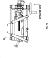
- the machine M is seen in the butt fusion mitered joint configuration of Figure 7B with pipes P mitered and ready for fusion at a proximal angle from the viewpoint of an operator standing in front of the machine M.
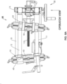
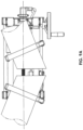
- the machine M is seen in the socket fusion mitered joint configuration of Figure 8A with a socket S and a pipe P mitered and ready for fusion at a distal angle from the viewpoint of an operator standing in front of the machine M.
Landscapes
- Engineering & Computer Science (AREA)
- Mechanical Engineering (AREA)
- Physics & Mathematics (AREA)
- Fluid Mechanics (AREA)
- Lining Or Joining Of Plastics Or The Like (AREA)
- Branch Pipes, Bends, And The Like (AREA)
Applications Claiming Priority (3)
| Application Number | Priority Date | Filing Date | Title |
|---|---|---|---|
| US15/709,470 US10751950B2 (en) | 2017-09-20 | 2017-09-20 | Pipe fusion machine |
| EP18859021.0A EP3684597B1 (fr) | 2017-09-20 | 2018-11-14 | Machine de raccordement de tuyaux par fusion |
| PCT/US2018/061064 WO2019060928A1 (fr) | 2017-09-20 | 2018-11-14 | Machine de raccordement de tuyaux par fusion |
Related Parent Applications (2)
| Application Number | Title | Priority Date | Filing Date |
|---|---|---|---|
| EP18859021.0A Division-Into EP3684597B1 (fr) | 2017-09-20 | 2018-11-14 | Machine de raccordement de tuyaux par fusion |
| EP18859021.0A Division EP3684597B1 (fr) | 2017-09-20 | 2018-11-14 | Machine de raccordement de tuyaux par fusion |
Publications (2)
| Publication Number | Publication Date |
|---|---|
| EP4338939A2 true EP4338939A2 (fr) | 2024-03-20 |
| EP4338939A3 EP4338939A3 (fr) | 2024-06-12 |
Family
ID=63788021
Family Applications (2)
| Application Number | Title | Priority Date | Filing Date |
|---|---|---|---|
| EP18859021.0A Active EP3684597B1 (fr) | 2017-09-20 | 2018-11-14 | Machine de raccordement de tuyaux par fusion |
| EP24154672.0A Pending EP4338939A3 (fr) | 2017-09-20 | 2018-11-14 | Machine de fusion de tuyaux |
Family Applications Before (1)
| Application Number | Title | Priority Date | Filing Date |
|---|---|---|---|
| EP18859021.0A Active EP3684597B1 (fr) | 2017-09-20 | 2018-11-14 | Machine de raccordement de tuyaux par fusion |
Country Status (6)
| Country | Link |
|---|---|
| US (3) | US10751950B2 (fr) |
| EP (2) | EP3684597B1 (fr) |
| AU (2) | AU2018335587B2 (fr) |
| CA (2) | CA3154223A1 (fr) |
| GB (1) | GB2581644A (fr) |
| WO (1) | WO2019060928A1 (fr) |
Families Citing this family (12)
| Publication number | Priority date | Publication date | Assignee | Title |
|---|---|---|---|---|
| US10751950B2 (en) * | 2017-09-20 | 2020-08-25 | Mcelroy Manufacturing, Inc. | Pipe fusion machine |
| US11078742B2 (en) * | 2018-05-13 | 2021-08-03 | Schlumberger Technology Corporation | BOP health monitoring system and method |
| CN110170957A (zh) * | 2019-06-06 | 2019-08-27 | 湖北金牛管业有限公司 | 电磁热熔管管材管件安装对接对中装置及其使用方法 |
| CN111016187A (zh) * | 2020-01-16 | 2020-04-17 | 孙艳 | 一种塑管热熔器 |
| CN112277325B (zh) * | 2020-11-03 | 2025-03-21 | 李朝晖 | 一种运用于大口径管材的热熔方法和热熔器 |
| WO2022262157A1 (fr) * | 2021-06-14 | 2022-12-22 | 胡德创 | Dispositif de serrage et d'obturation automatique pour conduite de gaz combustible, dispositif de fixation et conduit de fumée respectueux de l'environnement |
| CN113334778B (zh) * | 2021-06-18 | 2022-01-04 | 石奇 | 一种热塑性塑料管件的紧固装置及抗氧化加热方法 |
| CN116045076A (zh) * | 2022-12-02 | 2023-05-02 | 湖南易正物联科技有限公司 | 一种消防工程施工用管道预埋装置 |
| CN117698147B (zh) * | 2023-12-28 | 2025-04-08 | 杭州飞腾管业有限公司 | 一种mpp电力管熔接装置 |
| CN119042404B (zh) * | 2024-09-30 | 2026-04-17 | 中交石油天然气管道工程有限公司 | 一种石油天然气输送管道连接用辅助对接设备 |
| CN119189339B (zh) * | 2024-11-06 | 2025-05-13 | 杭州飞腾管业有限公司 | 一种pvc管铺设用连接设备 |
| CN119589964B (zh) * | 2025-02-10 | 2025-07-04 | 扬州市鸿信线路器材有限公司 | 一种电力电缆保护管热接加工设备 |
Family Cites Families (26)
| Publication number | Priority date | Publication date | Assignee | Title |
|---|---|---|---|---|
| US2538640A (en) * | 1947-05-01 | 1951-01-16 | Aubrey H Click | Unitary clamp for multiple surfaces in frictional engagement |
| DE2212055C3 (de) | 1972-03-13 | 1979-01-25 | Alfred Dipl.-Ing. 7250 Leonberg Ruehle | Vorrichtung zum Verschweißen von koaxial liegenden Rohren aus thermoplastischem Kunststoff |
| JPS586329B2 (ja) | 1974-09-03 | 1983-02-04 | 松下電器産業株式会社 | ハンドウタイチエンソウチ |
| US4008118A (en) | 1975-12-30 | 1977-02-15 | Emerson Electric Co. | Butt fusion machine |
| DE2734911C3 (de) | 1977-08-03 | 1980-03-20 | Widos Wilhelm Dommer Soehne Gmbh, 7257 Ditzingen | Vorrichtung zum Einschweißen eines Kunststoff-Rohres in ein Kunststoff-Formstück |
| CH640775A5 (de) | 1979-10-11 | 1984-01-31 | Fischer Ag Georg | Einrichtung zum verschweissen von koaxial liegenden rohrenden oder von rohrenden mit fittings aus kunststoff. |
| GB2172947B (en) | 1985-03-25 | 1988-07-27 | British Gas Plc | Apparatus for fusion joining of thermoplastic pipes |
| CH675392A5 (fr) | 1989-03-23 | 1990-09-28 | Fischer Ag Georg | |
| JP3086703B2 (ja) | 1990-04-06 | 2000-09-11 | ロックリング コーポレイション | 管継手の改良された荷重支持装置を備えた油圧組立工具 |
| DK284790D0 (da) * | 1990-11-29 | 1990-11-29 | Lars Erik Brath | Fremgangsmaade og apparat til sammensmeltning af separate termoplastiske legemer |
| DE69310329T2 (de) | 1992-12-16 | 1998-01-02 | Tdw Delaware Inc | Vorrichtung zum Stumpfschweissen von Kunststoffrohren |
| US5406587A (en) | 1993-02-08 | 1995-04-11 | Zenith Electronics Corporation | Error tracking loop |
| JP3586329B2 (ja) | 1995-12-27 | 2004-11-10 | 積水化学工業株式会社 | 融着機 |
| JP2000167934A (ja) | 1998-12-01 | 2000-06-20 | Sekisui Chem Co Ltd | 融着機 |
| JP2000167933A (ja) | 1998-12-01 | 2000-06-20 | Sekisui Chem Co Ltd | 融着機 |
| US6406587B1 (en) * | 1999-09-30 | 2002-06-18 | Connectra Fusion Technologies, Llc | Method and an apparatus for fusing a sidewall fitting onto a plastic pipe |
| IT1306729B1 (it) * | 1999-10-22 | 2001-10-02 | Giovanni Meirana | Pressa plurifunzionale per la saldatura di tubi e raccordi inmateriale plastico, in particolare in polietilene pe, polipropilene |
| US6550514B1 (en) * | 2000-03-29 | 2003-04-22 | Connectra Fusion Technologies, Llc | Indexer system for use with a plastic pipe butt-fusion machine |
| US7731297B1 (en) * | 2007-06-21 | 2010-06-08 | Ozanich Anthony R | Tailgate-securing dump apron for dump trucks |
| US8678363B2 (en) * | 2010-09-16 | 2014-03-25 | Christopher E. Baker | Multiple vise system |
| TWM424215U (en) * | 2011-08-12 | 2012-03-11 | Jin-Yuan Li | Power vise with push-pressing mechanism |
| US9505113B2 (en) * | 2012-07-20 | 2016-11-29 | Richard C Raczuk | Assembly tool and method of using |
| US8978699B2 (en) * | 2012-09-07 | 2015-03-17 | Cameron International Corporation | Blowout preventer status assembly |
| US10449724B2 (en) | 2015-07-28 | 2019-10-22 | Ahmet KOYUN | Butt welding machine with a cutter for a plastic pipe comprising a drive gear unit |
| CN208469083U (zh) * | 2017-09-12 | 2019-02-05 | 无锡市胜达塑管熔接设备有限公司 | 一种热熔焊机管道加持固定机构 |
| US10751950B2 (en) * | 2017-09-20 | 2020-08-25 | Mcelroy Manufacturing, Inc. | Pipe fusion machine |
-
2017
- 2017-09-20 US US15/709,470 patent/US10751950B2/en active Active
-
2018
- 2018-11-14 CA CA3154223A patent/CA3154223A1/fr active Pending
- 2018-11-14 CA CA3072977A patent/CA3072977C/fr active Active
- 2018-11-14 EP EP18859021.0A patent/EP3684597B1/fr active Active
- 2018-11-14 GB GB2005518.2A patent/GB2581644A/en not_active Withdrawn
- 2018-11-14 WO PCT/US2018/061064 patent/WO2019060928A1/fr not_active Ceased
- 2018-11-14 EP EP24154672.0A patent/EP4338939A3/fr active Pending
- 2018-11-14 AU AU2018335587A patent/AU2018335587B2/en active Active
-
2020
- 2020-08-21 US US16/999,881 patent/US11458693B2/en active Active
-
2022
- 2022-10-03 US US17/937,685 patent/US20230095782A1/en not_active Abandoned
-
2023
- 2023-11-23 AU AU2023270301A patent/AU2023270301B2/en active Active
Also Published As
| Publication number | Publication date |
|---|---|
| AU2023270301B2 (en) | 2025-10-23 |
| EP3684597B1 (fr) | 2024-03-06 |
| EP3684597A1 (fr) | 2020-07-29 |
| AU2023270301A1 (en) | 2023-12-14 |
| EP3684597A4 (fr) | 2021-07-21 |
| CA3154223A1 (fr) | 2019-03-28 |
| WO2019060928A9 (fr) | 2019-07-04 |
| US20230095782A1 (en) | 2023-03-30 |
| US20190084250A1 (en) | 2019-03-21 |
| EP4338939A3 (fr) | 2024-06-12 |
| US11458693B2 (en) | 2022-10-04 |
| AU2018335587B2 (en) | 2023-08-24 |
| WO2019060928A1 (fr) | 2019-03-28 |
| CA3072977C (fr) | 2022-06-21 |
| AU2018335587A1 (en) | 2020-03-12 |
| US20200376777A1 (en) | 2020-12-03 |
| CA3072977A1 (fr) | 2019-03-28 |
| GB202005518D0 (en) | 2020-06-03 |
| US10751950B2 (en) | 2020-08-25 |
| GB2581644A (en) | 2020-08-26 |
Similar Documents
| Publication | Publication Date | Title |
|---|---|---|
| US11458693B2 (en) | Pipe fusion machine | |
| US3552239A (en) | Portable drill press | |
| US9227240B2 (en) | Crimping head for impact wrench | |
| US20150139774A1 (en) | Rotary chuck | |
| US20130269500A1 (en) | Apparatus for Machining, Particularly for Cutting a Tubular or Round Section Body | |
| CN104321160A (zh) | 具有快速释放插入件的焊接头的可调节的夹持机构 | |
| US11938648B2 (en) | Apparatus for hole-making in an elongated, tubular body, and method of use of the apparatus | |
| AU2006200331B2 (en) | Bending device for bending machine | |
| PT2085188E (pt) | Alicate extensor | |
| CN215091553U (zh) | 一种高压导电管双向倾斜焊接平台 | |
| CN221121197U (zh) | 一种水利工程管道口对接支撑装置 | |
| CN119189320A (zh) | 焊接机器 | |
| CN216913445U (zh) | 一种平口钳 | |
| CN110497125A (zh) | 一种同轴可调节式法兰对口器 | |
| CN213828080U (zh) | 跑步机扁头轴加工爪盘机构 | |
| CN215658687U (zh) | 一种便于建筑铝合金模板转角c槽件焊接定位夹持装置 | |
| CN102784931B (zh) | 一种中心主轴夹紧机构 | |
| CN121104940A (zh) | 一种便携式快速调节开口的轻型管钳 | |
| TH62812B (th) | เครื่องหนีบจับ |
Legal Events
| Date | Code | Title | Description |
|---|---|---|---|
| PUAI | Public reference made under article 153(3) epc to a published international application that has entered the european phase |
Free format text: ORIGINAL CODE: 0009012 |
|
| STAA | Information on the status of an ep patent application or granted ep patent |
Free format text: STATUS: THE APPLICATION HAS BEEN PUBLISHED |
|
| AC | Divisional application: reference to earlier application |
Ref document number: 3684597 Country of ref document: EP Kind code of ref document: P |
|
| AK | Designated contracting states |
Kind code of ref document: A2 Designated state(s): AL AT BE BG CH CY CZ DE DK EE ES FI FR GB GR HR HU IE IS IT LI LT LU LV MC MK MT NL NO PL PT RO RS SE SI SK SM TR |
|
| REG | Reference to a national code |
Ref country code: DE Ref legal event code: R079 Free format text: PREVIOUS MAIN CLASS: B29C0065780000 Ipc: B29C0065020000 |
|
| PUAL | Search report despatched |
Free format text: ORIGINAL CODE: 0009013 |
|
| AK | Designated contracting states |
Kind code of ref document: A3 Designated state(s): AL AT BE BG CH CY CZ DE DK EE ES FI FR GB GR HR HU IE IS IT LI LT LU LV MC MK MT NL NO PL PT RO RS SE SI SK SM TR |
|
| RIC1 | Information provided on ipc code assigned before grant |
Ipc: B29K 23/00 20060101ALN20240503BHEP Ipc: B29L 23/00 20060101ALN20240503BHEP Ipc: B29C 65/78 20060101ALI20240503BHEP Ipc: B29C 65/02 20060101AFI20240503BHEP |
|
| STAA | Information on the status of an ep patent application or granted ep patent |
Free format text: STATUS: REQUEST FOR EXAMINATION WAS MADE |
|
| 17P | Request for examination filed |
Effective date: 20241212 |