EP4338940B1 - Modulare windturbinenschaufel und verfahren zur herstellung davon - Google Patents
Modulare windturbinenschaufel und verfahren zur herstellung davon Download PDFInfo
- Publication number
- EP4338940B1 EP4338940B1 EP22832235.0A EP22832235A EP4338940B1 EP 4338940 B1 EP4338940 B1 EP 4338940B1 EP 22832235 A EP22832235 A EP 22832235A EP 4338940 B1 EP4338940 B1 EP 4338940B1
- Authority
- EP
- European Patent Office
- Prior art keywords
- wind turbine
- turbine blade
- modular
- edge
- blade
- Prior art date
- Legal status (The legal status is an assumption and is not a legal conclusion. Google has not performed a legal analysis and makes no representation as to the accuracy of the status listed.)
- Active
Links
Images


Classifications
-
- B—PERFORMING OPERATIONS; TRANSPORTING
- B29—WORKING OF PLASTICS; WORKING OF SUBSTANCES IN A PLASTIC STATE IN GENERAL
- B29D—PRODUCING PARTICULAR ARTICLES FROM PLASTICS OR FROM SUBSTANCES IN A PLASTIC STATE
- B29D99/00—Subject matter not provided for in other groups of this subclass
- B29D99/0025—Producing blades or the like, e.g. blades for turbines, propellers, or wings
- B29D99/0028—Producing blades or the like, e.g. blades for turbines, propellers, or wings hollow blades
-
- B—PERFORMING OPERATIONS; TRANSPORTING
- B29—WORKING OF PLASTICS; WORKING OF SUBSTANCES IN A PLASTIC STATE IN GENERAL
- B29C—SHAPING OR JOINING OF PLASTICS; SHAPING OF MATERIAL IN A PLASTIC STATE, NOT OTHERWISE PROVIDED FOR; AFTER-TREATMENT OF THE SHAPED PRODUCTS, e.g. REPAIRING
- B29C39/00—Shaping by casting, i.e. introducing the moulding material into a mould or between confining surfaces without significant moulding pressure; Apparatus therefor
- B29C39/02—Shaping by casting, i.e. introducing the moulding material into a mould or between confining surfaces without significant moulding pressure; Apparatus therefor for making articles of definite length, i.e. discrete articles
-
- B—PERFORMING OPERATIONS; TRANSPORTING
- B29—WORKING OF PLASTICS; WORKING OF SUBSTANCES IN A PLASTIC STATE IN GENERAL
- B29C—SHAPING OR JOINING OF PLASTICS; SHAPING OF MATERIAL IN A PLASTIC STATE, NOT OTHERWISE PROVIDED FOR; AFTER-TREATMENT OF THE SHAPED PRODUCTS, e.g. REPAIRING
- B29C39/00—Shaping by casting, i.e. introducing the moulding material into a mould or between confining surfaces without significant moulding pressure; Apparatus therefor
- B29C39/22—Component parts, details or accessories; Auxiliary operations
- B29C39/26—Moulds or cores
-
- B—PERFORMING OPERATIONS; TRANSPORTING
- B29—WORKING OF PLASTICS; WORKING OF SUBSTANCES IN A PLASTIC STATE IN GENERAL
- B29C—SHAPING OR JOINING OF PLASTICS; SHAPING OF MATERIAL IN A PLASTIC STATE, NOT OTHERWISE PROVIDED FOR; AFTER-TREATMENT OF THE SHAPED PRODUCTS, e.g. REPAIRING
- B29C39/00—Shaping by casting, i.e. introducing the moulding material into a mould or between confining surfaces without significant moulding pressure; Apparatus therefor
- B29C39/22—Component parts, details or accessories; Auxiliary operations
- B29C39/42—Casting under special conditions, e.g. vacuum
-
- B—PERFORMING OPERATIONS; TRANSPORTING
- B29—WORKING OF PLASTICS; WORKING OF SUBSTANCES IN A PLASTIC STATE IN GENERAL
- B29C—SHAPING OR JOINING OF PLASTICS; SHAPING OF MATERIAL IN A PLASTIC STATE, NOT OTHERWISE PROVIDED FOR; AFTER-TREATMENT OF THE SHAPED PRODUCTS, e.g. REPAIRING
- B29C43/00—Compression moulding, i.e. applying external pressure to flow the moulding material; Apparatus therefor
- B29C43/02—Compression moulding, i.e. applying external pressure to flow the moulding material; Apparatus therefor of articles of definite length, i.e. discrete articles
- B29C43/14—Compression moulding, i.e. applying external pressure to flow the moulding material; Apparatus therefor of articles of definite length, i.e. discrete articles in several steps
-
- B—PERFORMING OPERATIONS; TRANSPORTING
- B29—WORKING OF PLASTICS; WORKING OF SUBSTANCES IN A PLASTIC STATE IN GENERAL
- B29C—SHAPING OR JOINING OF PLASTICS; SHAPING OF MATERIAL IN A PLASTIC STATE, NOT OTHERWISE PROVIDED FOR; AFTER-TREATMENT OF THE SHAPED PRODUCTS, e.g. REPAIRING
- B29C43/00—Compression moulding, i.e. applying external pressure to flow the moulding material; Apparatus therefor
- B29C43/32—Component parts, details or accessories; Auxiliary operations
- B29C43/36—Moulds for making articles of definite length, i.e. discrete articles
-
- B—PERFORMING OPERATIONS; TRANSPORTING
- B29—WORKING OF PLASTICS; WORKING OF SUBSTANCES IN A PLASTIC STATE IN GENERAL
- B29C—SHAPING OR JOINING OF PLASTICS; SHAPING OF MATERIAL IN A PLASTIC STATE, NOT OTHERWISE PROVIDED FOR; AFTER-TREATMENT OF THE SHAPED PRODUCTS, e.g. REPAIRING
- B29C43/00—Compression moulding, i.e. applying external pressure to flow the moulding material; Apparatus therefor
- B29C43/32—Component parts, details or accessories; Auxiliary operations
- B29C43/56—Compression moulding under special conditions, e.g. vacuum
-
- B—PERFORMING OPERATIONS; TRANSPORTING
- B29—WORKING OF PLASTICS; WORKING OF SUBSTANCES IN A PLASTIC STATE IN GENERAL
- B29C—SHAPING OR JOINING OF PLASTICS; SHAPING OF MATERIAL IN A PLASTIC STATE, NOT OTHERWISE PROVIDED FOR; AFTER-TREATMENT OF THE SHAPED PRODUCTS, e.g. REPAIRING
- B29C70/00—Shaping composites, i.e. plastics material comprising reinforcements, fillers or preformed parts, e.g. inserts
- B29C70/04—Shaping composites, i.e. plastics material comprising reinforcements, fillers or preformed parts, e.g. inserts comprising reinforcements only, e.g. self-reinforcing plastics
- B29C70/28—Shaping operations therefor
- B29C70/40—Shaping or impregnating by compression not applied
- B29C70/42—Shaping or impregnating by compression not applied for producing articles of definite length, i.e. discrete articles
- B29C70/44—Shaping or impregnating by compression not applied for producing articles of definite length, i.e. discrete articles using isostatic pressure, e.g. pressure difference-moulding, vacuum bag-moulding, autoclave-moulding or expanding rubber-moulding
- B29C70/443—Shaping or impregnating by compression not applied for producing articles of definite length, i.e. discrete articles using isostatic pressure, e.g. pressure difference-moulding, vacuum bag-moulding, autoclave-moulding or expanding rubber-moulding and impregnating by vacuum or injection
-
- F—MECHANICAL ENGINEERING; LIGHTING; HEATING; WEAPONS; BLASTING
- F03—MACHINES OR ENGINES FOR LIQUIDS; WIND, SPRING, OR WEIGHT MOTORS; PRODUCING MECHANICAL POWER OR A REACTIVE PROPULSIVE THRUST, NOT OTHERWISE PROVIDED FOR
- F03D—WIND MOTORS
- F03D1/00—Wind motors with rotation axis substantially parallel to the air flow entering the rotor
- F03D1/06—Rotors
- F03D1/065—Rotors characterised by their construction elements
- F03D1/0675—Rotors characterised by their construction elements of the blades
- F03D1/0677—Longitudinally segmented blades; Connectors therefor
-
- F—MECHANICAL ENGINEERING; LIGHTING; HEATING; WEAPONS; BLASTING
- F03—MACHINES OR ENGINES FOR LIQUIDS; WIND, SPRING, OR WEIGHT MOTORS; PRODUCING MECHANICAL POWER OR A REACTIVE PROPULSIVE THRUST, NOT OTHERWISE PROVIDED FOR
- F03D—WIND MOTORS
- F03D1/00—Wind motors with rotation axis substantially parallel to the air flow entering the rotor
- F03D1/06—Rotors
- F03D1/065—Rotors characterised by their construction elements
- F03D1/0675—Rotors characterised by their construction elements of the blades
- F03D1/0679—Load carrying structures, e.g. beams
-
- F—MECHANICAL ENGINEERING; LIGHTING; HEATING; WEAPONS; BLASTING
- F03—MACHINES OR ENGINES FOR LIQUIDS; WIND, SPRING, OR WEIGHT MOTORS; PRODUCING MECHANICAL POWER OR A REACTIVE PROPULSIVE THRUST, NOT OTHERWISE PROVIDED FOR
- F03D—WIND MOTORS
- F03D13/00—Assembly, mounting or commissioning of wind motors; Arrangements specially adapted for transporting wind motor components
- F03D13/30—Commissioning, e.g. inspection, testing or final adjustment before releasing for production
-
- B—PERFORMING OPERATIONS; TRANSPORTING
- B29—WORKING OF PLASTICS; WORKING OF SUBSTANCES IN A PLASTIC STATE IN GENERAL
- B29C—SHAPING OR JOINING OF PLASTICS; SHAPING OF MATERIAL IN A PLASTIC STATE, NOT OTHERWISE PROVIDED FOR; AFTER-TREATMENT OF THE SHAPED PRODUCTS, e.g. REPAIRING
- B29C43/00—Compression moulding, i.e. applying external pressure to flow the moulding material; Apparatus therefor
- B29C43/32—Component parts, details or accessories; Auxiliary operations
- B29C43/56—Compression moulding under special conditions, e.g. vacuum
- B29C2043/561—Compression moulding under special conditions, e.g. vacuum under vacuum conditions
-
- F—MECHANICAL ENGINEERING; LIGHTING; HEATING; WEAPONS; BLASTING
- F05—INDEXING SCHEMES RELATING TO ENGINES OR PUMPS IN VARIOUS SUBCLASSES OF CLASSES F01-F04
- F05B—INDEXING SCHEME RELATING TO WIND, SPRING, WEIGHT, INERTIA OR LIKE MOTORS, TO MACHINES OR ENGINES FOR LIQUIDS COVERED BY SUBCLASSES F03B, F03D AND F03G
- F05B2230/00—Manufacture
- F05B2230/60—Assembly methods
-
- F—MECHANICAL ENGINEERING; LIGHTING; HEATING; WEAPONS; BLASTING
- F05—INDEXING SCHEMES RELATING TO ENGINES OR PUMPS IN VARIOUS SUBCLASSES OF CLASSES F01-F04
- F05B—INDEXING SCHEME RELATING TO WIND, SPRING, WEIGHT, INERTIA OR LIKE MOTORS, TO MACHINES OR ENGINES FOR LIQUIDS COVERED BY SUBCLASSES F03B, F03D AND F03G
- F05B2240/00—Components
- F05B2240/20—Rotors
- F05B2240/30—Characteristics of rotor blades, i.e. of any element transforming dynamic fluid energy to or from rotational energy and being attached to a rotor
- F05B2240/302—Segmented or sectional blades
-
- Y—GENERAL TAGGING OF NEW TECHNOLOGICAL DEVELOPMENTS; GENERAL TAGGING OF CROSS-SECTIONAL TECHNOLOGIES SPANNING OVER SEVERAL SECTIONS OF THE IPC; TECHNICAL SUBJECTS COVERED BY FORMER USPC CROSS-REFERENCE ART COLLECTIONS [XRACs] AND DIGESTS
- Y02—TECHNOLOGIES OR APPLICATIONS FOR MITIGATION OR ADAPTATION AGAINST CLIMATE CHANGE
- Y02E—REDUCTION OF GREENHOUSE GAS [GHG] EMISSIONS, RELATED TO ENERGY GENERATION, TRANSMISSION OR DISTRIBUTION
- Y02E10/00—Energy generation through renewable energy sources
- Y02E10/70—Wind energy
- Y02E10/72—Wind turbines with rotation axis in wind direction
-
- Y—GENERAL TAGGING OF NEW TECHNOLOGICAL DEVELOPMENTS; GENERAL TAGGING OF CROSS-SECTIONAL TECHNOLOGIES SPANNING OVER SEVERAL SECTIONS OF THE IPC; TECHNICAL SUBJECTS COVERED BY FORMER USPC CROSS-REFERENCE ART COLLECTIONS [XRACs] AND DIGESTS
- Y02—TECHNOLOGIES OR APPLICATIONS FOR MITIGATION OR ADAPTATION AGAINST CLIMATE CHANGE
- Y02P—CLIMATE CHANGE MITIGATION TECHNOLOGIES IN THE PRODUCTION OR PROCESSING OF GOODS
- Y02P70/00—Climate change mitigation technologies in the production process for final industrial or consumer products
- Y02P70/50—Manufacturing or production processes characterised by the final manufactured product
Definitions
- the invention relates to the technical field of wind power generation equipment, in particular to a modular wind turbine blade and a manufacturing method thereof.
- EP 196507 4B1 discloses a wind turbine multi-panel blade.
- the wind turbine blade comprises at least one central spar longitudinal section composed of two cap prefabricated panels and two web prefabricated panels placed side by side in a box shape and at least two shell longitudinal sections forming, respectively, the leading edge and the trailing edge of the corresponding blade section that are placed adjacently to a central spar section and are composed of a single prefabricated panel or of two prefabricated panels, the aerodynamic profile of the blade being defined by said cap panels and said single shell panels or said two shell panels.
- the technical problem to be solved by the present invention is to provide a modular wind turbine blade and a manufacturing method thereof, effectively reducing the mold occupation time of wind turbine blades.
- the present invention proposes a modular wind turbine blade comprising a blade root, an intermediate portion and a blade tip, wherein the intermediate portion comprises a plurality of modular blades, two adjacent modular blades being provided at edge thereof with a first connecting portion and a second connecting portion that cooperate with each other, and wherein the plurality of modular blades includes several trailing edge shells, several leading edge shells and several main beams, respectively, the first connecting portion at the edge of the trailing edge shell and the leading edge shell being fixedly connected to the second connecting portion at the edge of the main beam.
- the main beam includes a main support beam for connecting the leading edge shell and a secondary support beam for connecting the trailing edge shell, the main support beam being fixedly connected to the secondary support beam through the cooperation of the first connecting portion and the second connecting portion.
- the main support beam and the secondary support beam are each provided with a connecting beam, the connecting beam being vertically provided with a fixing recess for fixing a web, the corner of the fixing recess and the connecting beam being an arc transition.
- the main support beam resembles a shovel-shaped structure close to the connection end of the wind turbine blade segments and a connecting edge extends towards the interior of the wind turbine blade along the edge of the shovel-shaped structure, an end of the connecting edge intersecting with the connecting beam to form a closed area.
- the first connecting portion is a boss and the second connecting portion is provided with a recess matching the first connecting portion, the boss being embedded in the recess and fixedly connected by means of structural adhesive.
- an enhancement limiting edge of the connecting edge located between the two symmetrical bent edges is provided perpendicular to the connecting beam, and a distance is left between the enhancement limiting edge and the connecting end of the wind turbine blade.
- the present invention also provides a method for manufacturing a modular wind turbine blade described above, comprising the following steps:
- the forming process of the modular blade comprises the steps of:
- the assembly process of the wind turbine blade comprises the steps of:
- the post-processing comprises:
- the advantageous effects of the present invention lie in that the wind turbine blade according to the present invention adopts segmented modular structure design, which effectively reduces the mold occupancy time of the blade, shortening the production cycle and improving the molding efficiency.
- a plurality of modular blade structures adopt modular molding and modular adhesive assembly, which saves transportation cost.
- a plurality of modular blades are connected by means of bosses cooperating with the recesses, and their bosses are embedded in the recesses so that the rounded ends of the bosses fit closely with the arc at the bottom of the recesses, and the recesses wrap around the outside of the bosses to form a sandwich structure, which increases the ability to withstand shear loads and improves the anti-destabilization ability.
- the thicker areas in the shell of the blade root and blade tip are made by vacuum bagging method of semi-impregnated low-temperature prepreg with 60% fiber content, which reduces the weight of the blade, and the skin area of the intermediate portion is made by vacuum infusion of hand layup resin, which effectively improves the molding efficiency and reduces the production cost.
- the blade root is a tubular structure having a length of 3-5 meters, which is convenient for the application of the winding process, and the weight of the blade root is reduced by at least 30% by the winding process.
- a modular wind turbine blade shown in FIGS. 1 to 4 comprises a blade root 1, an intermediate portion 2 and a blade tip 3, wherein the intermediate portion 2 comprises a plurality of modular blades, two adjacent modular blades being provided at edge thereof with a first connecting portion 4 and a second connecting portion 5 that cooperate with each other, and wherein the plurality of modular blades includes several trailing edge shells 21, several leading edge shells 22 and several main beams 23, respectively, the first connecting portion 4 at the edge of the trailing edge shell 21 and the leading edge shell 22 being fixedly connected to the second connecting portion 5 at the edge of the main beam 23.
- the wind turbine blade according to the present invention adopts segmented modular structure design, which effectively reduces the mold occupancy time of the blade, shortening the production cycle and improving the molding efficiency.
- the main beam 23 includes a main support beam 231 for connecting the leading edge shell 22 and a secondary support beam 232 for connecting the trailing edge shell 21, the main support beam 231 being fixedly connected to the secondary support beam 232 through the cooperation of the first connecting portion 4 and the second connecting portion 5.
- main support beam 231 and the secondary support beam 232 are each provided with a connecting beam 233, the connecting beam 233 being vertically provided with a fixing recess 2331 for fixing a web 24, the corner of the fixing recess 2331 and the connecting beam 233 being an arc transition.
- the arc transition increases the strength of the fixing recess 2331 and ensures the stability of the connection of the web 24.
- the first connecting portion 4 is a boss and the second connecting portion 5 is provided with a recess matching the first connecting portion 4, the boss being embedded in the recess and fixedly connected by means of structural adhesive.
- a plurality of modular blades are connected by means of bosses cooperating with the recesses, and their bosses are embedded in the recesses so that the rounded ends of the bosses fit closely with the arc at the bottom of the recesses, and the recesses wrap around the outside of the bosses to form a sandwich structure, which increases the ability to withstand shear loads.
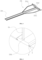
- the main support beam 231 resembles a shovel-shaped structure close to the connection end of the wind turbine blade segments and a connecting edge extends towards the interior of the wind turbine blade along the edge of the shovel-shaped structure, an end of the connecting edge intersecting with the connecting beam 233 to form a closed area.
- the end of the connecting edge intersects with the connecting beam 233 to form a closed area, which ensures the strength of the main support beam 231 itself,thus improving the wind turbine blade's overall ability to bear the load.
- the combination of the two connection forms of the bent edge and the first connecting portion 4 realizes the double reinforcement of the joint of the modular blades, increasing the stability of the connection between the leading edge shell 22 and the trailing edge shell 21 and the main beam 23, and improving the anti-destabilization capacity of the leading edge shell 22 and the trailing edge shell 21.
- the width direction of the cavity of the trailing edge shell 21 refers to the horizontal direction from the trailing edge shell 21 to the leading edge shell 22.
- the reinforcement limiting edge 2312 of the connecting edge located between the two symmetrical bent edges 2311 is provided perpendicular to the connecting beam 233, and the reinforcement limiting edge 2312 has a certain distance from the connecting end of the wind turbine blade.
- the reinforcement limiting edge 2312 ensures the reliability of the connection of the modularized blades along the length direction.
- the present invention also provides a method for manufacturing a modular wind turbine blade described above, comprising the following steps:
- the cavity of the blade tip 3 is narrow and integrally formed, which ensures the controllability of the quality and improves the reliability of the performance of the wind turbine blade.
- the blade root 1 is a tubular structure in the range of 3-5 meters, the blade root 1 can be formed by winding process and vacuum bagging method. The winding process reduces the weight of the blade root by 30%, and the automatic winding improves forming efficiency.
- the thicker areas in the shell of the blade root 1 and blade tip 3 are made by vacuum bagging method of semi-impregnated low-temperature prepreg with 60% fiber content, which reduces the weight of the blade, and the skin area of the intermediate portion 2 is made by vacuum infusion of hand layup resin, which effectively improves the molding efficiency and reduces the production cost.
- the assembly process comprises: cutting and cleaning the burrs of the demolded modular blade and completing surface polishing;
- the post-processing process comprises: transferring the cooled wind turbine blade blank to a punching station (or a blade root grinding station);
- the post-processing process in the present invention cancels the external reinforcement station and cutting and grinding station, since the external reinforcement treatment and cutting and grinding treatment are completed in the assembly process, in which the reinforcement treatment is carried out on the assembly tooling and the cutting and grinding is carried out on the transfer tooling, reducing the post-processing station and shortening the post-processing cycle.
Landscapes
- Engineering & Computer Science (AREA)
- Mechanical Engineering (AREA)
- Chemical & Material Sciences (AREA)
- Life Sciences & Earth Sciences (AREA)
- Sustainable Development (AREA)
- Sustainable Energy (AREA)
- Combustion & Propulsion (AREA)
- General Engineering & Computer Science (AREA)
- Composite Materials (AREA)
- Wind Motors (AREA)
Claims (7)
- Modulare Windturbinenschaufel, umfassend einen Schaufelfuß (1), einen mittleren Abschnitt (2) und eine Schaufelspitze (3), wobei der mittlere Abschnitt (2) eine Vielzahl von modularen Schaufeln umfasst, wobei zwei benachbarte modulare Schaufeln an einer Kante derselben mit einem ersten Verbindungsabschnitt (4) und einem zweiten Verbindungsabschnitt (5) versehen sind, die miteinander zusammenwirken, und wobei die Vielzahl von modularen Schaufeln jeweils mehrere Vorderkantenmäntel (21), mehrere Hinterkantenmäntel (22) und mehrere Hauptholme (23) umfasst, wobei der erste Verbindungsabschnitt (4) an der Kante des Hinterkantenmantels (21) und des Vorderkantenmantels (22) fest mit dem zweiten Verbindungsabschnitt (5) an der Kante des Hauptholms (23) verbunden sind; dadurch gekennzeichnet, dassder Hauptholm (23) einen Hauptträgerholm (231) zum Verbinden des Vorderkantenmantels (22) und einen sekundären Trägerholm (232) zum Verbinden des Hinterkantenmantels (21) beinhaltet, wobei der Hauptträgerholm (231) durch das Zusammenwirken des ersten Verbindungsabschnitts (4) und des zweiten Verbindungsabschnitts (5) fest mit dem sekundären Trägerholm (232) verbunden ist;der Hauptträgerholm (231) und der sekundäre Trägerholm (232) jeweils mit einem Verbindungsholm (233) versehen sind, wobei der Verbindungsholm (233) vertikal mit einer Fixierungsvertiefung (2331) zum Fixieren eines Stegs (24) versehen ist, wobei die Ecke der Fixierungsvertiefung (2331) und der Verbindungsholm (233) einen Bogenübegang vollziehen;der Hauptträgerholm (231) nah am Verbindungsende der Windturbinenschaufelsegmente einer löffelförmigen Struktur gleicht und sich eine Verbindungskante entlang der Kante der löffelförmigen Struktur in Richtung des Inneren der Windturbinenschaufel erstreckt, wobei ein Ende der Verbindungskante den Verbindungsholm (233) schneidet, um einen geschlossenen Bereich zu bilden; undwobei der geschlossene Bereich die Form eines symmetrischen Trapezes aufweist, der sekundäre Trägerholm (232) und der Vorderkantenmantel (22) mit einem Montagebereich versehen sind, der dem Trapez entspricht, und der Montagebereich an seiner Kante mit einer Fixierungskante versehen ist, die zu einer gebogenen Kante (2311) der Verbindungskante passt.
- Modulare Windturbinenschaufel nach Anspruch 1, wobei der erste Verbindungsabschnitt (4) ein Ansatz ist und der zweite Verbindungsabschnitt (5) mit einer Vertiefung versehen ist, die zu dem ersten Verbindungsabschnitt passt, wobei der Ansatz in die Vertiefung eingebettet und mittels eines Konstruktionsklebstoffs fest verbunden ist.
- Modulare Windturbinenschaufel nach Anspruch 1, wobei eine Verstärkungsbegrenzungskante (2312) der Verbindungskante zwischen den beiden symmetrischen gebogenen Kanten (2311) senkrecht zu dem Verbindungsholm (233) bereitgestellt ist und ein Abstand zwischen der Verstärkungsbegrenzungskante (2312) und der Verbindungskante der Windturbinenschaufel belassen ist.
- Verfahren zum Herstellen der modularen Windturbinenschaufel nach einem der Ansprüche 1 bis 3, folgende Schritte umfassend:S1: Bilden des Fußes (1) und der Spitze (3) der Windturbinenschaufel unter Verwendung eines Vakuumbeutelverfahrens und Bilden der Vielzahl von modularen Schaufeln des mittleren Abschnitts (2) unter Verwendung eines Vakuuminfusionsverfahrens;S2: nach dem Verfestigen und Entfernen aus der Form Durchführen der Montage unter Verwendung einer anderen Produktionslinie, um einen Windturbinenschaufelrohling zu bilden; undS3: Durchführen von Nachbearbeitung an dem Windturbinenschaufelrohling, um das fertige Windturbinenschaufelprodukt zu erlangen.
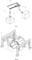
- Verfahren zum Herstellen einer modularen Windturbinenschaufel nach Anspruch 4, wobei in S1 der Prozess des Bildens der modularen Schaufel folgende Schritte umfasst:Reinigen einer Form (9) der modularen Schaufel und Beschichten der Formoberfläche mit einem Formtrennmittel;Auslegen einer geschichteten Mantelstruktur (8) in der Form (9);Auslegen eines integrierten Infusionssystems (6) und eines integrierten Silikonvakuumsystems (7), die zuvor hergestellt wurden, im Bereich der Mantelstruktur (8), Anbringen von Klebebändern und Beibehalten des Drucks;Durchführen der Vakuuminfusion von Handauflageharz nach einer Dichtigkeitsprüfung des Vakuumbereichs;Vorhärten der Form (9) durch Erwärmen nach Abschluss der Infusion; undAbsenken der gehärteten modularen Schaufel auf Raumtemperatur gefolgt von Entfernen der modularen Schaufel aus der Form und Reinigen der Form (9).
- Verfahren zum Herstellen einer modularen Windturbinenschaufel nach Anspruch 5, wobei in S2 der Prozess der Montage der modularen Schaufel folgende Schritte umfasst:Schneiden und Entfernen der Grate der aus der Form entfernten modularen Schaufel und Abschließen der Oberflächenpolierung;Übertragen der geschnittenen und polierten modularen Schaufel an eine entsprechende Station der Montageplattform, wo das Modul mittels einer Saugnapfvorrichtung (10) positioniert wird;Auftragen eines Konstruktionsklebstoffs auf die Kantenverbindungsoberfläche der modularen Schaufel und aufeinanderfolgendes Verbinden der Vielzahl von modularen Schaufeln;Durchführen einer äußeren Verstärkungsbehandlung an dem montierten Windturbinenschaufelrohling;Erwärmen des Windturbinenschaufelrohlings durch einen Nachhärtungsofen, um den Windturbinenschaufelrohling zu härten; undÜbertragen des gehärteten Windturbinenschaufelrohlings aus dem Nachhärtungsofen in einen Lagerbereich zum Abkühlen.
- Verfahren zum Herstellen einer modularen Windturbinenschaufel nach Anspruch 6, wobei in S3 die Nachbearbeitung der modularen Schaufel folgende Schritte umfasst:Übertragen des gekühlten Windturbinenschaufelrohlings an eine Stanzstation (oder eine Schaufelfußschleifstation);Verarbeiten des Schaufelfußes gemäß den Prozessparametern;Übertragen der bearbeiteten Schaufel an eine Lackierungsstation;Reinigen des Windturbinenschaufelrohlings;Dichten des Windturbinenschaufelrohlings nach der Wartung und Durchführen einer Formprüfung nach dem Aushärten der Spachtelmasse;Lackieren des Windturbinenschaufelrohlings nach der Formprüfung;Durchführen einer Sonderanfertigung an dem Windturbinenschaufelrohling gemäß den Kundenanforderungen; undDurchführen einer Sonderprüfung vor der Lieferung und Übertragen der qualifizierten Schaufeln in den Lagerbereich.
Applications Claiming Priority (2)
| Application Number | Priority Date | Filing Date | Title |
|---|---|---|---|
| CN202111063538.3A CN113787658B (zh) | 2021-09-10 | 2021-09-10 | 模块化风电叶片及其制造方法 |
| PCT/CN2022/114461 WO2023274423A1 (zh) | 2021-09-10 | 2022-08-24 | 模块化风电叶片及其制造方法 |
Publications (4)
| Publication Number | Publication Date |
|---|---|
| EP4338940A1 EP4338940A1 (de) | 2024-03-20 |
| EP4338940A4 EP4338940A4 (de) | 2024-10-02 |
| EP4338940C0 EP4338940C0 (de) | 2025-04-16 |
| EP4338940B1 true EP4338940B1 (de) | 2025-04-16 |
Family
ID=79183131
Family Applications (1)
| Application Number | Title | Priority Date | Filing Date |
|---|---|---|---|
| EP22832235.0A Active EP4338940B1 (de) | 2021-09-10 | 2022-08-24 | Modulare windturbinenschaufel und verfahren zur herstellung davon |
Country Status (4)
| Country | Link |
|---|---|
| US (1) | US12311627B2 (de) |
| EP (1) | EP4338940B1 (de) |
| CN (1) | CN113787658B (de) |
| WO (1) | WO2023274423A1 (de) |
Families Citing this family (10)
| Publication number | Priority date | Publication date | Assignee | Title |
|---|---|---|---|---|
| CN113787658B (zh) | 2021-09-10 | 2022-06-14 | 常州市宏发纵横新材料科技股份有限公司 | 模块化风电叶片及其制造方法 |
| CN114962134A (zh) * | 2022-03-31 | 2022-08-30 | 振石集团华智研究院(浙江)有限公司 | 一种风电叶片用结构增强件及风电叶片 |
| CN115263660B (zh) | 2022-08-01 | 2025-10-28 | 三一重能股份有限公司 | 风力发电叶片装置和风力发电设备 |
| CN115306632A (zh) * | 2022-08-09 | 2022-11-08 | 国电联合动力技术有限公司 | 组块化大型风电机组叶片及风力发电机 |
| CN116116674A (zh) * | 2022-12-15 | 2023-05-16 | 国能联合动力技术(连云港)有限公司 | 风机叶片自动化涂装方法及系统 |
| CN115977866B (zh) * | 2023-03-20 | 2023-05-23 | 新创碳谷集团有限公司 | 一种模块化风电叶片及其连接结构 |
| CN115977867B (zh) * | 2023-03-20 | 2023-06-09 | 新创碳谷集团有限公司 | 一种分段式叶片模块结构及其成型方法 |
| CN116039124B (zh) * | 2023-04-03 | 2023-06-13 | 新创碳谷集团有限公司 | 一种模块化分段叶片后缘整体成型工装及成型工艺 |
| CN116104688B (zh) * | 2023-04-17 | 2023-06-27 | 新创碳谷集团有限公司 | 一种两段式风电叶片连接结构 |
| CN117507380B (zh) * | 2023-12-07 | 2024-06-14 | 新创碳谷集团有限公司 | 一种模块化叶片主梁粘接装置及方法 |
Family Cites Families (21)
| Publication number | Priority date | Publication date | Assignee | Title |
|---|---|---|---|---|
| ES2342638B1 (es) * | 2007-02-28 | 2011-05-13 | GAMESA INNOVATION & TECHNOLOGY, S.L. | Una pala de aerogenerador multi-panel. |
| DE102007010858A1 (de) * | 2007-03-01 | 2008-09-11 | Brose Fahrzeugteile Gmbh & Co. Kommanditgesellschaft, Hallstadt | Verfahren und Vorrichtung zur Herstellung eines Aggregateträgers für eine Kraftfahrzeugtür sowie Aggregateträger hierfür |
| ES2343712B1 (es) * | 2007-05-03 | 2011-05-18 | Manuel Torres Martinez | Pala de aerogenerador dividida en tramos y proceso de fabricacion de la misma. |
| CN101749194B (zh) * | 2009-12-11 | 2011-09-14 | 重庆通用工业(集团)有限责任公司 | 一种大型风力发电机组风轮叶片及其成型方法 |
| BR112014015243A8 (pt) * | 2011-12-21 | 2019-01-22 | Wobben Properties Gmbh | receptáculo de uma instalação de energia eólica, instalação de energia eólica, e, método de construção de uma instalação de energia eólica |
| CN103144312A (zh) * | 2013-03-28 | 2013-06-12 | 重庆通用工业(集团)有限责任公司 | 一种叶片前后缘外补强真空灌注热固化成型工艺 |
| US9610739B2 (en) * | 2013-04-17 | 2017-04-04 | Lm Wp Patent Holding A/S | Wind turbine blade repair method |
| EP2881237B1 (de) * | 2013-12-03 | 2019-06-26 | LM WP Patent Holding A/S | Verfahren zur Herstellung eines Schernetzes mit einem vorgeformten Bahnfußflansch |
| EP3002452B1 (de) * | 2014-10-05 | 2019-07-24 | Pontis Group Holding B.V. | Windturbinenschaufel |
| US9951750B2 (en) * | 2015-07-30 | 2018-04-24 | General Electric Company | Rotor blade with interior shelf for a flat plate spar cap |
| CN105508131B (zh) * | 2016-01-18 | 2018-01-16 | 明阳智慧能源集团股份公司 | 一种分段组合式风力发电机叶片及其制造方法 |
| CN106499578B (zh) * | 2016-12-18 | 2023-11-21 | 中国科学院工程热物理研究所 | 一种风电叶片叶尖延长结构及方法 |
| US10865769B2 (en) * | 2017-11-21 | 2020-12-15 | General Electric Company | Methods for manufacturing wind turbine rotor blade panels having printed grid structures |
| GB201905852D0 (en) * | 2019-04-26 | 2019-06-12 | Blade Dynamics Ltd | Wind turbine blade and method for producing a wind turbine blade |
| EP3808972B1 (de) * | 2019-10-18 | 2026-04-29 | VENSYS Energy AG | Verbindung zwischen längssegmenten eines rotorblattes des rotors einer windenergieanlage |
| DE102019128487A1 (de) * | 2019-10-18 | 2021-04-22 | Vensys Energy Ag | Verbindung zwischen Längssegmenten eines Rotorblattes des Rotors einer Windenergieanlage |
| CN111775456A (zh) * | 2020-07-07 | 2020-10-16 | 株洲时代新材料科技股份有限公司 | 一种凹形主梁风电叶片的制作方法及凹形主梁风电叶片 |
| CN113137346B (zh) * | 2021-05-08 | 2022-09-30 | 上海电气风电集团股份有限公司 | 一种分段式风机叶片及其装配方法 |
| CN113323797A (zh) * | 2021-08-03 | 2021-08-31 | 常州市宏发纵横新材料科技股份有限公司 | 一种模块化风电叶片 |
| CN113787658B (zh) * | 2021-09-10 | 2022-06-14 | 常州市宏发纵横新材料科技股份有限公司 | 模块化风电叶片及其制造方法 |
| CN216767625U (zh) * | 2022-03-08 | 2022-06-17 | 常州市宏发纵横新材料科技股份有限公司 | 模块化风电叶片分块连接结构 |
-
2021
- 2021-09-10 CN CN202111063538.3A patent/CN113787658B/zh active Active
-
2022
- 2022-08-24 EP EP22832235.0A patent/EP4338940B1/de active Active
- 2022-08-24 WO PCT/CN2022/114461 patent/WO2023274423A1/zh not_active Ceased
-
2023
- 2023-07-24 US US18/225,508 patent/US12311627B2/en active Active
Also Published As
| Publication number | Publication date |
|---|---|
| WO2023274423A1 (zh) | 2023-01-05 |
| EP4338940A4 (de) | 2024-10-02 |
| EP4338940C0 (de) | 2025-04-16 |
| EP4338940A1 (de) | 2024-03-20 |
| CN113787658B (zh) | 2022-06-14 |
| CN113787658A (zh) | 2021-12-14 |
| US20230364875A1 (en) | 2023-11-16 |
| US12311627B2 (en) | 2025-05-27 |
Similar Documents
| Publication | Publication Date | Title |
|---|---|---|
| EP4338940B1 (de) | Modulare windturbinenschaufel und verfahren zur herstellung davon | |
| CN102076485B (zh) | 风力涡轮机的转子叶片的制造方法 | |
| EP3964352B1 (de) | Leichter holmgurt mit einer konkaven struktur für eine windturbinenschaufel und herstellungsverfahren dafür | |
| CN208431094U (zh) | 一种风电叶片主梁结构 | |
| CN111608852A (zh) | 一种轻量化风机叶片及其制作方法 | |
| CN113757036B (zh) | 一种改进后缘结构的风电叶片及其制作方法 | |
| CN115573854B (zh) | 一种模块化风电叶片及制造方法 | |
| CN101670635B (zh) | 模制加强抗剪腹板芯部 | |
| CN115742343B (zh) | 一种榫卯连接的复合材料翼面及其成型方法 | |
| CN106499578B (zh) | 一种风电叶片叶尖延长结构及方法 | |
| US12392319B2 (en) | Modular wind turbine blade structure and manufacturing method thereof | |
| CN105673358A (zh) | 一种大型尾缘分段风力机叶片连接结构及制作工艺 | |
| CN111923443A (zh) | 一种风电叶片及其成型方法 | |
| CN111791503A (zh) | 一种风力发电叶片腹板及其制造方法 | |
| CN112848349A (zh) | 一种根部拼接式风电叶片及其制作方法 | |
| CN217123700U (zh) | 一种用于分段叶片模块制造的模具结构 | |
| CN214726637U (zh) | 一种根部拼接式风电叶片 | |
| CN221272078U (zh) | 一种风电叶片腹板锐角粘接法兰脱模模具 | |
| CN208452344U (zh) | 一种风电叶片双大梁模具 | |
| CN113199786B (zh) | 风机叶片用腹板的制造方法 | |
| CN211008948U (zh) | 一种风力发电机叶片用的梁帽结构 | |
| CN111188727B (zh) | 一种风力机叶根结构及其生产方法 | |
| CN201679621U (zh) | 兆瓦级风力发电机多梁结构玻璃钢空腹叶片 | |
| CN216866894U (zh) | 一种四分段式风电叶片模块结构 | |
| CN221113104U (zh) | 一种smmc结构、电池盒上盖及电池盒 |
Legal Events
| Date | Code | Title | Description |
|---|---|---|---|
| STAA | Information on the status of an ep patent application or granted ep patent |
Free format text: STATUS: THE INTERNATIONAL PUBLICATION HAS BEEN MADE |
|
| PUAI | Public reference made under article 153(3) epc to a published international application that has entered the european phase |
Free format text: ORIGINAL CODE: 0009012 |
|
| STAA | Information on the status of an ep patent application or granted ep patent |
Free format text: STATUS: REQUEST FOR EXAMINATION WAS MADE |
|
| 17P | Request for examination filed |
Effective date: 20231212 |
|
| AK | Designated contracting states |
Kind code of ref document: A1 Designated state(s): AL AT BE BG CH CY CZ DE DK EE ES FI FR GB GR HR HU IE IS IT LI LT LU LV MC MK MT NL NO PL PT RO RS SE SI SK SM TR |
|
| A4 | Supplementary search report drawn up and despatched |
Effective date: 20240903 |
|
| RIC1 | Information provided on ipc code assigned before grant |
Ipc: F03D 13/00 20160101ALI20240828BHEP Ipc: F03D 1/06 20060101ALI20240828BHEP Ipc: B29C 70/00 20060101AFI20240828BHEP |
|
| DAV | Request for validation of the european patent (deleted) | ||
| DAX | Request for extension of the european patent (deleted) | ||
| GRAP | Despatch of communication of intention to grant a patent |
Free format text: ORIGINAL CODE: EPIDOSNIGR1 |
|
| STAA | Information on the status of an ep patent application or granted ep patent |
Free format text: STATUS: GRANT OF PATENT IS INTENDED |
|
| INTG | Intention to grant announced |
Effective date: 20241223 |
|
| GRAS | Grant fee paid |
Free format text: ORIGINAL CODE: EPIDOSNIGR3 |
|
| GRAA | (expected) grant |
Free format text: ORIGINAL CODE: 0009210 |
|
| STAA | Information on the status of an ep patent application or granted ep patent |
Free format text: STATUS: THE PATENT HAS BEEN GRANTED |
|
| AK | Designated contracting states |
Kind code of ref document: B1 Designated state(s): AL AT BE BG CH CY CZ DE DK EE ES FI FR GB GR HR HU IE IS IT LI LT LU LV MC MK MT NL NO PL PT RO RS SE SI SK SM TR |
|
| REG | Reference to a national code |
Ref country code: GB Ref legal event code: FG4D |
|
| REG | Reference to a national code |
Ref country code: CH Ref legal event code: EP |
|
| REG | Reference to a national code |
Ref country code: IE Ref legal event code: FG4D |
|
| U01 | Request for unitary effect filed |
Effective date: 20250422 |
|
| U07 | Unitary effect registered |
Designated state(s): AT BE BG DE DK EE FI FR IT LT LU LV MT NL PT RO SE SI Effective date: 20250425 |
|
| U20 | Renewal fee for the european patent with unitary effect paid |
Year of fee payment: 4 Effective date: 20250606 |
|
| PG25 | Lapsed in a contracting state [announced via postgrant information from national office to epo] |
Ref country code: ES Free format text: LAPSE BECAUSE OF FAILURE TO SUBMIT A TRANSLATION OF THE DESCRIPTION OR TO PAY THE FEE WITHIN THE PRESCRIBED TIME-LIMIT Effective date: 20250416 |
|
| PG25 | Lapsed in a contracting state [announced via postgrant information from national office to epo] |
Ref country code: GR Free format text: LAPSE BECAUSE OF FAILURE TO SUBMIT A TRANSLATION OF THE DESCRIPTION OR TO PAY THE FEE WITHIN THE PRESCRIBED TIME-LIMIT Effective date: 20250717 Ref country code: NO Free format text: LAPSE BECAUSE OF FAILURE TO SUBMIT A TRANSLATION OF THE DESCRIPTION OR TO PAY THE FEE WITHIN THE PRESCRIBED TIME-LIMIT Effective date: 20250716 |
|
| PG25 | Lapsed in a contracting state [announced via postgrant information from national office to epo] |
Ref country code: PL Free format text: LAPSE BECAUSE OF FAILURE TO SUBMIT A TRANSLATION OF THE DESCRIPTION OR TO PAY THE FEE WITHIN THE PRESCRIBED TIME-LIMIT Effective date: 20250416 |
|
| PG25 | Lapsed in a contracting state [announced via postgrant information from national office to epo] |
Ref country code: HR Free format text: LAPSE BECAUSE OF FAILURE TO SUBMIT A TRANSLATION OF THE DESCRIPTION OR TO PAY THE FEE WITHIN THE PRESCRIBED TIME-LIMIT Effective date: 20250416 |
|
| PG25 | Lapsed in a contracting state [announced via postgrant information from national office to epo] |
Ref country code: RS Free format text: LAPSE BECAUSE OF FAILURE TO SUBMIT A TRANSLATION OF THE DESCRIPTION OR TO PAY THE FEE WITHIN THE PRESCRIBED TIME-LIMIT Effective date: 20250716 |
|
| PG25 | Lapsed in a contracting state [announced via postgrant information from national office to epo] |
Ref country code: IS Free format text: LAPSE BECAUSE OF FAILURE TO SUBMIT A TRANSLATION OF THE DESCRIPTION OR TO PAY THE FEE WITHIN THE PRESCRIBED TIME-LIMIT Effective date: 20250816 |
|
| PG25 | Lapsed in a contracting state [announced via postgrant information from national office to epo] |
Ref country code: SM Free format text: LAPSE BECAUSE OF FAILURE TO SUBMIT A TRANSLATION OF THE DESCRIPTION OR TO PAY THE FEE WITHIN THE PRESCRIBED TIME-LIMIT Effective date: 20250416 |
|
| PG25 | Lapsed in a contracting state [announced via postgrant information from national office to epo] |
Ref country code: CZ Free format text: LAPSE BECAUSE OF FAILURE TO SUBMIT A TRANSLATION OF THE DESCRIPTION OR TO PAY THE FEE WITHIN THE PRESCRIBED TIME-LIMIT Effective date: 20250416 |
|
| PG25 | Lapsed in a contracting state [announced via postgrant information from national office to epo] |
Ref country code: SK Free format text: LAPSE BECAUSE OF FAILURE TO SUBMIT A TRANSLATION OF THE DESCRIPTION OR TO PAY THE FEE WITHIN THE PRESCRIBED TIME-LIMIT Effective date: 20250416 |
|
| PLBE | No opposition filed within time limit |
Free format text: ORIGINAL CODE: 0009261 |
|
| STAA | Information on the status of an ep patent application or granted ep patent |
Free format text: STATUS: NO OPPOSITION FILED WITHIN TIME LIMIT |
|
| REG | Reference to a national code |
Ref country code: CH Ref legal event code: L10 Free format text: ST27 STATUS EVENT CODE: U-0-0-L10-L00 (AS PROVIDED BY THE NATIONAL OFFICE) Effective date: 20260225 |
|
| REG | Reference to a national code |
Ref country code: CH Ref legal event code: H13 Free format text: ST27 STATUS EVENT CODE: U-0-0-H10-H13 (AS PROVIDED BY THE NATIONAL OFFICE) Effective date: 20260324 |
|
| 26N | No opposition filed |
Effective date: 20260119 |
|
| PG25 | Lapsed in a contracting state [announced via postgrant information from national office to epo] |
Ref country code: MC Free format text: LAPSE BECAUSE OF FAILURE TO SUBMIT A TRANSLATION OF THE DESCRIPTION OR TO PAY THE FEE WITHIN THE PRESCRIBED TIME-LIMIT Effective date: 20250416 |
|
| PG25 | Lapsed in a contracting state [announced via postgrant information from national office to epo] |
Ref country code: CH Free format text: LAPSE BECAUSE OF NON-PAYMENT OF DUE FEES Effective date: 20250831 |