EP4338941A1 - Verfahren zur herstellung eines verbundstoffmaterialformartikels, verfahren zur herstellung einer halterung und eines wälzlagers und verfahren zur herstellung einer getriebebestandteils - Google Patents
Verfahren zur herstellung eines verbundstoffmaterialformartikels, verfahren zur herstellung einer halterung und eines wälzlagers und verfahren zur herstellung einer getriebebestandteils Download PDFInfo
- Publication number
- EP4338941A1 EP4338941A1 EP22807567.7A EP22807567A EP4338941A1 EP 4338941 A1 EP4338941 A1 EP 4338941A1 EP 22807567 A EP22807567 A EP 22807567A EP 4338941 A1 EP4338941 A1 EP 4338941A1
- Authority
- EP
- European Patent Office
- Prior art keywords
- preform
- resin
- gear box
- producing
- mold
- Prior art date
- Legal status (The legal status is an assumption and is not a legal conclusion. Google has not performed a legal analysis and makes no representation as to the accuracy of the status listed.)
- Pending
Links
- 238000004519 manufacturing process Methods 0.000 title claims abstract description 48
- 239000002131 composite material Substances 0.000 title claims abstract description 23
- 238000005096 rolling process Methods 0.000 title claims description 58
- 239000000470 constituent Substances 0.000 title description 4
- 229920005989 resin Polymers 0.000 claims abstract description 136
- 239000011347 resin Substances 0.000 claims abstract description 136
- 239000012783 reinforcing fiber Substances 0.000 claims abstract description 83
- 238000000465 moulding Methods 0.000 claims abstract description 61
- 229920001187 thermosetting polymer Polymers 0.000 claims abstract description 55
- 239000000835 fiber Substances 0.000 claims abstract description 53
- 239000002904 solvent Substances 0.000 claims abstract description 25
- 238000000034 method Methods 0.000 claims description 114
- 230000008569 process Effects 0.000 claims description 72
- 239000000463 material Substances 0.000 claims description 50
- 229910052751 metal Inorganic materials 0.000 claims description 45
- 239000002184 metal Substances 0.000 claims description 45
- 230000007246 mechanism Effects 0.000 claims description 29
- 230000009467 reduction Effects 0.000 claims description 12
- 229920000049 Carbon (fiber) Polymers 0.000 claims description 11
- 239000004917 carbon fiber Substances 0.000 claims description 11
- 238000000748 compression moulding Methods 0.000 claims description 9
- 239000003365 glass fiber Substances 0.000 claims description 9
- 239000000843 powder Substances 0.000 claims description 9
- 238000011049 filling Methods 0.000 claims description 7
- 239000005011 phenolic resin Substances 0.000 claims description 7
- 229920006231 aramid fiber Polymers 0.000 claims description 6
- VNWKTOKETHGBQD-UHFFFAOYSA-N methane Chemical compound C VNWKTOKETHGBQD-UHFFFAOYSA-N 0.000 claims description 6
- 239000003822 epoxy resin Substances 0.000 claims description 5
- 229920000647 polyepoxide Polymers 0.000 claims description 5
- 238000012546 transfer Methods 0.000 claims description 5
- 229920001721 polyimide Polymers 0.000 claims description 4
- -1 polyparaphenylene Polymers 0.000 claims description 4
- XQUPVDVFXZDTLT-UHFFFAOYSA-N 1-[4-[[4-(2,5-dioxopyrrol-1-yl)phenyl]methyl]phenyl]pyrrole-2,5-dione Chemical compound O=C1C=CC(=O)N1C(C=C1)=CC=C1CC1=CC=C(N2C(C=CC2=O)=O)C=C1 XQUPVDVFXZDTLT-UHFFFAOYSA-N 0.000 claims description 3
- 229920003043 Cellulose fiber Polymers 0.000 claims description 3
- 229920000265 Polyparaphenylene Polymers 0.000 claims description 3
- 238000005304 joining Methods 0.000 claims description 3
- 229920003192 poly(bis maleimide) Polymers 0.000 claims description 3
- 229920001230 polyarylate Polymers 0.000 claims description 3
- 239000009719 polyimide resin Substances 0.000 claims description 3
- 229920005992 thermoplastic resin Polymers 0.000 claims description 3
- 238000002156 mixing Methods 0.000 abstract description 3
- 238000010586 diagram Methods 0.000 description 18
- 239000011342 resin composition Substances 0.000 description 17
- 238000012360 testing method Methods 0.000 description 17
- 239000000243 solution Substances 0.000 description 13
- 230000006835 compression Effects 0.000 description 11
- 238000007906 compression Methods 0.000 description 11
- 238000005452 bending Methods 0.000 description 8
- 150000002739 metals Chemical class 0.000 description 7
- 238000012545 processing Methods 0.000 description 6
- 238000005461 lubrication Methods 0.000 description 5
- 239000000203 mixture Substances 0.000 description 5
- 230000003014 reinforcing effect Effects 0.000 description 5
- XLYOFNOQVPJJNP-UHFFFAOYSA-N water Substances O XLYOFNOQVPJJNP-UHFFFAOYSA-N 0.000 description 5
- 239000000654 additive Substances 0.000 description 4
- 239000004760 aramid Substances 0.000 description 4
- 239000003795 chemical substances by application Substances 0.000 description 4
- 239000007822 coupling agent Substances 0.000 description 4
- 238000010438 heat treatment Methods 0.000 description 4
- 238000003825 pressing Methods 0.000 description 4
- 239000013585 weight reducing agent Substances 0.000 description 4
- OKKJLVBELUTLKV-UHFFFAOYSA-N Methanol Chemical compound OC OKKJLVBELUTLKV-UHFFFAOYSA-N 0.000 description 3
- 239000000853 adhesive Substances 0.000 description 3
- 230000001070 adhesive effect Effects 0.000 description 3
- 238000005520 cutting process Methods 0.000 description 3
- 230000007423 decrease Effects 0.000 description 3
- 230000000694 effects Effects 0.000 description 3
- 239000012765 fibrous filler Substances 0.000 description 3
- 239000007788 liquid Substances 0.000 description 3
- 239000004033 plastic Substances 0.000 description 3
- 229920003023 plastic Polymers 0.000 description 3
- 239000002002 slurry Substances 0.000 description 3
- 229920003002 synthetic resin Polymers 0.000 description 3
- 239000000057 synthetic resin Substances 0.000 description 3
- ZOXJGFHDIHLPTG-UHFFFAOYSA-N Boron Chemical compound [B] ZOXJGFHDIHLPTG-UHFFFAOYSA-N 0.000 description 2
- LFQSCWFLJHTTHZ-UHFFFAOYSA-N Ethanol Chemical compound CCO LFQSCWFLJHTTHZ-UHFFFAOYSA-N 0.000 description 2
- XEEYBQQBJWHFJM-UHFFFAOYSA-N Iron Chemical compound [Fe] XEEYBQQBJWHFJM-UHFFFAOYSA-N 0.000 description 2
- PXHVJJICTQNCMI-UHFFFAOYSA-N Nickel Chemical compound [Ni] PXHVJJICTQNCMI-UHFFFAOYSA-N 0.000 description 2
- 239000006087 Silane Coupling Agent Substances 0.000 description 2
- RTAQQCXQSZGOHL-UHFFFAOYSA-N Titanium Chemical compound [Ti] RTAQQCXQSZGOHL-UHFFFAOYSA-N 0.000 description 2
- PNEYBMLMFCGWSK-UHFFFAOYSA-N aluminium oxide Inorganic materials [O-2].[O-2].[O-2].[Al+3].[Al+3] PNEYBMLMFCGWSK-UHFFFAOYSA-N 0.000 description 2
- 229910052796 boron Inorganic materials 0.000 description 2
- 239000001913 cellulose Substances 0.000 description 2
- 229920002678 cellulose Polymers 0.000 description 2
- 239000011248 coating agent Substances 0.000 description 2
- 238000000576 coating method Methods 0.000 description 2
- 230000006866 deterioration Effects 0.000 description 2
- 239000004744 fabric Substances 0.000 description 2
- 230000009969 flowable effect Effects 0.000 description 2
- 239000004973 liquid crystal related substance Substances 0.000 description 2
- 238000003754 machining Methods 0.000 description 2
- 230000004048 modification Effects 0.000 description 2
- 238000012986 modification Methods 0.000 description 2
- 238000007747 plating Methods 0.000 description 2
- 229920006122 polyamide resin Polymers 0.000 description 2
- 229920000728 polyester Polymers 0.000 description 2
- 239000000126 substance Substances 0.000 description 2
- RNFJDJUURJAICM-UHFFFAOYSA-N 2,2,4,4,6,6-hexaphenoxy-1,3,5-triaza-2$l^{5},4$l^{5},6$l^{5}-triphosphacyclohexa-1,3,5-triene Chemical compound N=1P(OC=2C=CC=CC=2)(OC=2C=CC=CC=2)=NP(OC=2C=CC=CC=2)(OC=2C=CC=CC=2)=NP=1(OC=1C=CC=CC=1)OC1=CC=CC=C1 RNFJDJUURJAICM-UHFFFAOYSA-N 0.000 description 1
- 229910000838 Al alloy Inorganic materials 0.000 description 1
- 229910052582 BN Inorganic materials 0.000 description 1
- PZNSFCLAULLKQX-UHFFFAOYSA-N Boron nitride Chemical compound N#B PZNSFCLAULLKQX-UHFFFAOYSA-N 0.000 description 1
- OKTJSMMVPCPJKN-UHFFFAOYSA-N Carbon Chemical compound [C] OKTJSMMVPCPJKN-UHFFFAOYSA-N 0.000 description 1
- RYGMFSIKBFXOCR-UHFFFAOYSA-N Copper Chemical compound [Cu] RYGMFSIKBFXOCR-UHFFFAOYSA-N 0.000 description 1
- 229920000742 Cotton Polymers 0.000 description 1
- 239000004677 Nylon Substances 0.000 description 1
- 239000004696 Poly ether ether ketone Substances 0.000 description 1
- 239000004642 Polyimide Substances 0.000 description 1
- 239000004734 Polyphenylene sulfide Substances 0.000 description 1
- 238000005299 abrasion Methods 0.000 description 1
- 239000002253 acid Substances 0.000 description 1
- 230000009471 action Effects 0.000 description 1
- 230000000996 additive effect Effects 0.000 description 1
- 229910052782 aluminium Inorganic materials 0.000 description 1
- XAGFODPZIPBFFR-UHFFFAOYSA-N aluminium Chemical compound [Al] XAGFODPZIPBFFR-UHFFFAOYSA-N 0.000 description 1
- 239000003963 antioxidant agent Substances 0.000 description 1
- 230000003078 antioxidant effect Effects 0.000 description 1
- 239000002216 antistatic agent Substances 0.000 description 1
- 229920003235 aromatic polyamide Polymers 0.000 description 1
- 125000003118 aryl group Chemical group 0.000 description 1
- 229910052802 copper Inorganic materials 0.000 description 1
- 239000010949 copper Substances 0.000 description 1
- 238000002425 crystallisation Methods 0.000 description 1
- 230000008025 crystallization Effects 0.000 description 1
- 238000013036 cure process Methods 0.000 description 1
- 230000018044 dehydration Effects 0.000 description 1
- 238000006297 dehydration reaction Methods 0.000 description 1
- 238000001514 detection method Methods 0.000 description 1
- 239000000975 dye Substances 0.000 description 1
- 229920006351 engineering plastic Polymers 0.000 description 1
- 230000007613 environmental effect Effects 0.000 description 1
- 239000003063 flame retardant Substances 0.000 description 1
- 239000000446 fuel Substances 0.000 description 1
- 239000010439 graphite Substances 0.000 description 1
- 229910002804 graphite Inorganic materials 0.000 description 1
- 230000005484 gravity Effects 0.000 description 1
- 239000004519 grease Substances 0.000 description 1
- 239000012760 heat stabilizer Substances 0.000 description 1
- 230000001771 impaired effect Effects 0.000 description 1
- 238000005470 impregnation Methods 0.000 description 1
- 229910052742 iron Inorganic materials 0.000 description 1
- 239000000314 lubricant Substances 0.000 description 1
- 239000010687 lubricating oil Substances 0.000 description 1
- 238000002844 melting Methods 0.000 description 1
- 230000008018 melting Effects 0.000 description 1
- 239000007769 metal material Substances 0.000 description 1
- 239000010445 mica Substances 0.000 description 1
- 229910052618 mica group Inorganic materials 0.000 description 1
- 239000011259 mixed solution Substances 0.000 description 1
- 239000006082 mold release agent Substances 0.000 description 1
- CWQXQMHSOZUFJS-UHFFFAOYSA-N molybdenum disulfide Chemical compound S=[Mo]=S CWQXQMHSOZUFJS-UHFFFAOYSA-N 0.000 description 1
- 229910052982 molybdenum disulfide Inorganic materials 0.000 description 1
- 239000002121 nanofiber Substances 0.000 description 1
- 229910052759 nickel Inorganic materials 0.000 description 1
- 239000002667 nucleating agent Substances 0.000 description 1
- 229920001778 nylon Polymers 0.000 description 1
- 230000000704 physical effect Effects 0.000 description 1
- 239000000049 pigment Substances 0.000 description 1
- 239000004014 plasticizer Substances 0.000 description 1
- 229920002530 polyetherether ketone Polymers 0.000 description 1
- 229920000069 polyphenylene sulfide Polymers 0.000 description 1
- 238000012805 post-processing Methods 0.000 description 1
- 238000011417 postcuring Methods 0.000 description 1
- 238000007788 roughening Methods 0.000 description 1
- 239000005060 rubber Substances 0.000 description 1
- 230000035939 shock Effects 0.000 description 1
- HBMJWWWQQXIZIP-UHFFFAOYSA-N silicon carbide Chemical compound [Si+]#[C-] HBMJWWWQQXIZIP-UHFFFAOYSA-N 0.000 description 1
- 229910010271 silicon carbide Inorganic materials 0.000 description 1
- 239000007787 solid Substances 0.000 description 1
- 239000010935 stainless steel Substances 0.000 description 1
- 229910001220 stainless steel Inorganic materials 0.000 description 1
- 238000003756 stirring Methods 0.000 description 1
- 238000010998 test method Methods 0.000 description 1
- BFKJFAAPBSQJPD-UHFFFAOYSA-N tetrafluoroethene Chemical group FC(F)=C(F)F BFKJFAAPBSQJPD-UHFFFAOYSA-N 0.000 description 1
- ITRNXVSDJBHYNJ-UHFFFAOYSA-N tungsten disulfide Chemical compound S=[W]=S ITRNXVSDJBHYNJ-UHFFFAOYSA-N 0.000 description 1
- 239000006097 ultraviolet radiation absorber Substances 0.000 description 1
- 238000003466 welding Methods 0.000 description 1
- 239000002759 woven fabric Substances 0.000 description 1
Images




Classifications
-
- B—PERFORMING OPERATIONS; TRANSPORTING
- B29—WORKING OF PLASTICS; WORKING OF SUBSTANCES IN A PLASTIC STATE IN GENERAL
- B29C—SHAPING OR JOINING OF PLASTICS; SHAPING OF MATERIAL IN A PLASTIC STATE, NOT OTHERWISE PROVIDED FOR; AFTER-TREATMENT OF THE SHAPED PRODUCTS, e.g. REPAIRING
- B29C70/00—Shaping composites, i.e. plastics material comprising reinforcements, fillers or preformed parts, e.g. inserts
- B29C70/68—Shaping composites, i.e. plastics material comprising reinforcements, fillers or preformed parts, e.g. inserts by incorporating or moulding on preformed parts, e.g. inserts or layers, e.g. foam blocks
-
- B—PERFORMING OPERATIONS; TRANSPORTING
- B29—WORKING OF PLASTICS; WORKING OF SUBSTANCES IN A PLASTIC STATE IN GENERAL
- B29C—SHAPING OR JOINING OF PLASTICS; SHAPING OF MATERIAL IN A PLASTIC STATE, NOT OTHERWISE PROVIDED FOR; AFTER-TREATMENT OF THE SHAPED PRODUCTS, e.g. REPAIRING
- B29C70/00—Shaping composites, i.e. plastics material comprising reinforcements, fillers or preformed parts, e.g. inserts
- B29C70/04—Shaping composites, i.e. plastics material comprising reinforcements, fillers or preformed parts, e.g. inserts comprising reinforcements only, e.g. self-reinforcing plastics
- B29C70/28—Shaping operations therefor
- B29C70/40—Shaping or impregnating by compression not applied
- B29C70/42—Shaping or impregnating by compression not applied for producing articles of definite length, i.e. discrete articles
- B29C70/46—Shaping or impregnating by compression not applied for producing articles of definite length, i.e. discrete articles using matched moulds, e.g. for deforming sheet moulding compounds [SMC] or prepregs
- B29C70/462—Moulding structures having an axis of symmetry or at least one channel, e.g. tubular structures, frames
-
- B—PERFORMING OPERATIONS; TRANSPORTING
- B29—WORKING OF PLASTICS; WORKING OF SUBSTANCES IN A PLASTIC STATE IN GENERAL
- B29B—PREPARATION OR PRETREATMENT OF THE MATERIAL TO BE SHAPED; MAKING GRANULES OR PREFORMS; RECOVERY OF PLASTICS OR OTHER CONSTITUENTS OF WASTE MATERIAL CONTAINING PLASTICS
- B29B11/00—Making preforms
- B29B11/14—Making preforms characterised by structure or composition
- B29B11/16—Making preforms characterised by structure or composition comprising fillers or reinforcement
-
- B—PERFORMING OPERATIONS; TRANSPORTING
- B29—WORKING OF PLASTICS; WORKING OF SUBSTANCES IN A PLASTIC STATE IN GENERAL
- B29B—PREPARATION OR PRETREATMENT OF THE MATERIAL TO BE SHAPED; MAKING GRANULES OR PREFORMS; RECOVERY OF PLASTICS OR OTHER CONSTITUENTS OF WASTE MATERIAL CONTAINING PLASTICS
- B29B13/00—Conditioning or physical treatment of the material to be shaped
- B29B13/06—Conditioning or physical treatment of the material to be shaped by drying
-
- B—PERFORMING OPERATIONS; TRANSPORTING
- B29—WORKING OF PLASTICS; WORKING OF SUBSTANCES IN A PLASTIC STATE IN GENERAL
- B29C—SHAPING OR JOINING OF PLASTICS; SHAPING OF MATERIAL IN A PLASTIC STATE, NOT OTHERWISE PROVIDED FOR; AFTER-TREATMENT OF THE SHAPED PRODUCTS, e.g. REPAIRING
- B29C43/00—Compression moulding, i.e. applying external pressure to flow the moulding material; Apparatus therefor
- B29C43/003—Compression moulding, i.e. applying external pressure to flow the moulding material; Apparatus therefor characterised by the choice of material
-
- B—PERFORMING OPERATIONS; TRANSPORTING
- B29—WORKING OF PLASTICS; WORKING OF SUBSTANCES IN A PLASTIC STATE IN GENERAL
- B29C—SHAPING OR JOINING OF PLASTICS; SHAPING OF MATERIAL IN A PLASTIC STATE, NOT OTHERWISE PROVIDED FOR; AFTER-TREATMENT OF THE SHAPED PRODUCTS, e.g. REPAIRING
- B29C43/00—Compression moulding, i.e. applying external pressure to flow the moulding material; Apparatus therefor
- B29C43/02—Compression moulding, i.e. applying external pressure to flow the moulding material; Apparatus therefor of articles of definite length, i.e. discrete articles
- B29C43/18—Compression moulding, i.e. applying external pressure to flow the moulding material; Apparatus therefor of articles of definite length, i.e. discrete articles incorporating preformed parts or layers, e.g. compression moulding around inserts or for coating articles
-
- B—PERFORMING OPERATIONS; TRANSPORTING
- B29—WORKING OF PLASTICS; WORKING OF SUBSTANCES IN A PLASTIC STATE IN GENERAL
- B29C—SHAPING OR JOINING OF PLASTICS; SHAPING OF MATERIAL IN A PLASTIC STATE, NOT OTHERWISE PROVIDED FOR; AFTER-TREATMENT OF THE SHAPED PRODUCTS, e.g. REPAIRING
- B29C43/00—Compression moulding, i.e. applying external pressure to flow the moulding material; Apparatus therefor
- B29C43/32—Component parts, details or accessories; Auxiliary operations
- B29C43/52—Heating or cooling
-
- B—PERFORMING OPERATIONS; TRANSPORTING
- B29—WORKING OF PLASTICS; WORKING OF SUBSTANCES IN A PLASTIC STATE IN GENERAL
- B29C—SHAPING OR JOINING OF PLASTICS; SHAPING OF MATERIAL IN A PLASTIC STATE, NOT OTHERWISE PROVIDED FOR; AFTER-TREATMENT OF THE SHAPED PRODUCTS, e.g. REPAIRING
- B29C70/00—Shaping composites, i.e. plastics material comprising reinforcements, fillers or preformed parts, e.g. inserts
- B29C70/04—Shaping composites, i.e. plastics material comprising reinforcements, fillers or preformed parts, e.g. inserts comprising reinforcements only, e.g. self-reinforcing plastics
- B29C70/06—Fibrous reinforcements only
- B29C70/08—Fibrous reinforcements only comprising combinations of different forms of fibrous reinforcements incorporated in matrix material, forming one or more layers, and with or without non-reinforced layers
-
- B—PERFORMING OPERATIONS; TRANSPORTING
- B29—WORKING OF PLASTICS; WORKING OF SUBSTANCES IN A PLASTIC STATE IN GENERAL
- B29C—SHAPING OR JOINING OF PLASTICS; SHAPING OF MATERIAL IN A PLASTIC STATE, NOT OTHERWISE PROVIDED FOR; AFTER-TREATMENT OF THE SHAPED PRODUCTS, e.g. REPAIRING
- B29C70/00—Shaping composites, i.e. plastics material comprising reinforcements, fillers or preformed parts, e.g. inserts
- B29C70/04—Shaping composites, i.e. plastics material comprising reinforcements, fillers or preformed parts, e.g. inserts comprising reinforcements only, e.g. self-reinforcing plastics
- B29C70/06—Fibrous reinforcements only
- B29C70/10—Fibrous reinforcements only characterised by the structure of fibrous reinforcements, e.g. hollow fibres
- B29C70/12—Fibrous reinforcements only characterised by the structure of fibrous reinforcements, e.g. hollow fibres using fibres of short length, e.g. in the form of a mat
-
- B—PERFORMING OPERATIONS; TRANSPORTING
- B29—WORKING OF PLASTICS; WORKING OF SUBSTANCES IN A PLASTIC STATE IN GENERAL
- B29C—SHAPING OR JOINING OF PLASTICS; SHAPING OF MATERIAL IN A PLASTIC STATE, NOT OTHERWISE PROVIDED FOR; AFTER-TREATMENT OF THE SHAPED PRODUCTS, e.g. REPAIRING
- B29C70/00—Shaping composites, i.e. plastics material comprising reinforcements, fillers or preformed parts, e.g. inserts
- B29C70/04—Shaping composites, i.e. plastics material comprising reinforcements, fillers or preformed parts, e.g. inserts comprising reinforcements only, e.g. self-reinforcing plastics
- B29C70/28—Shaping operations therefor
- B29C70/40—Shaping or impregnating by compression not applied
- B29C70/42—Shaping or impregnating by compression not applied for producing articles of definite length, i.e. discrete articles
- B29C70/46—Shaping or impregnating by compression not applied for producing articles of definite length, i.e. discrete articles using matched moulds, e.g. for deforming sheet moulding compounds [SMC] or prepregs
-
- B—PERFORMING OPERATIONS; TRANSPORTING
- B29—WORKING OF PLASTICS; WORKING OF SUBSTANCES IN A PLASTIC STATE IN GENERAL
- B29C—SHAPING OR JOINING OF PLASTICS; SHAPING OF MATERIAL IN A PLASTIC STATE, NOT OTHERWISE PROVIDED FOR; AFTER-TREATMENT OF THE SHAPED PRODUCTS, e.g. REPAIRING
- B29C70/00—Shaping composites, i.e. plastics material comprising reinforcements, fillers or preformed parts, e.g. inserts
- B29C70/04—Shaping composites, i.e. plastics material comprising reinforcements, fillers or preformed parts, e.g. inserts comprising reinforcements only, e.g. self-reinforcing plastics
- B29C70/28—Shaping operations therefor
- B29C70/40—Shaping or impregnating by compression not applied
- B29C70/42—Shaping or impregnating by compression not applied for producing articles of definite length, i.e. discrete articles
- B29C70/46—Shaping or impregnating by compression not applied for producing articles of definite length, i.e. discrete articles using matched moulds, e.g. for deforming sheet moulding compounds [SMC] or prepregs
- B29C70/48—Shaping or impregnating by compression not applied for producing articles of definite length, i.e. discrete articles using matched moulds, e.g. for deforming sheet moulding compounds [SMC] or prepregs and impregnating the reinforcements in the closed mould, e.g. resin transfer moulding [RTM], e.g. by vacuum
-
- B—PERFORMING OPERATIONS; TRANSPORTING
- B29—WORKING OF PLASTICS; WORKING OF SUBSTANCES IN A PLASTIC STATE IN GENERAL
- B29C—SHAPING OR JOINING OF PLASTICS; SHAPING OF MATERIAL IN A PLASTIC STATE, NOT OTHERWISE PROVIDED FOR; AFTER-TREATMENT OF THE SHAPED PRODUCTS, e.g. REPAIRING
- B29C70/00—Shaping composites, i.e. plastics material comprising reinforcements, fillers or preformed parts, e.g. inserts
- B29C70/68—Shaping composites, i.e. plastics material comprising reinforcements, fillers or preformed parts, e.g. inserts by incorporating or moulding on preformed parts, e.g. inserts or layers, e.g. foam blocks
- B29C70/86—Incorporated in coherent impregnated reinforcing layers, e.g. by winding
-
- F—MECHANICAL ENGINEERING; LIGHTING; HEATING; WEAPONS; BLASTING
- F16—ENGINEERING ELEMENTS AND UNITS; GENERAL MEASURES FOR PRODUCING AND MAINTAINING EFFECTIVE FUNCTIONING OF MACHINES OR INSTALLATIONS; THERMAL INSULATION IN GENERAL
- F16C—SHAFTS; FLEXIBLE SHAFTS; ELEMENTS OR CRANKSHAFT MECHANISMS; ROTARY BODIES OTHER THAN GEARING ELEMENTS; BEARINGS
- F16C33/00—Parts of bearings; Special methods for making bearings or parts thereof
- F16C33/30—Parts of ball or roller bearings
- F16C33/38—Ball cages
- F16C33/3837—Massive or moulded cages having cage pockets surrounding the balls, e.g. machined window cages
- F16C33/3843—Massive or moulded cages having cage pockets surrounding the balls, e.g. machined window cages formed as one-piece cages, i.e. monoblock cages
- F16C33/3856—Massive or moulded cages having cage pockets surrounding the balls, e.g. machined window cages formed as one-piece cages, i.e. monoblock cages made from plastic, e.g. injection moulded window cages
-
- F—MECHANICAL ENGINEERING; LIGHTING; HEATING; WEAPONS; BLASTING
- F16—ENGINEERING ELEMENTS AND UNITS; GENERAL MEASURES FOR PRODUCING AND MAINTAINING EFFECTIVE FUNCTIONING OF MACHINES OR INSTALLATIONS; THERMAL INSULATION IN GENERAL
- F16C—SHAFTS; FLEXIBLE SHAFTS; ELEMENTS OR CRANKSHAFT MECHANISMS; ROTARY BODIES OTHER THAN GEARING ELEMENTS; BEARINGS
- F16C33/00—Parts of bearings; Special methods for making bearings or parts thereof
- F16C33/30—Parts of ball or roller bearings
- F16C33/46—Cages for rollers or needles
- F16C33/4617—Massive or moulded cages having cage pockets surrounding the rollers, e.g. machined window cages
- F16C33/4623—Massive or moulded cages having cage pockets surrounding the rollers, e.g. machined window cages formed as one-piece cages, i.e. monoblock cages
- F16C33/4635—Massive or moulded cages having cage pockets surrounding the rollers, e.g. machined window cages formed as one-piece cages, i.e. monoblock cages made from plastic, e.g. injection moulded window cages
-
- F—MECHANICAL ENGINEERING; LIGHTING; HEATING; WEAPONS; BLASTING
- F16—ENGINEERING ELEMENTS AND UNITS; GENERAL MEASURES FOR PRODUCING AND MAINTAINING EFFECTIVE FUNCTIONING OF MACHINES OR INSTALLATIONS; THERMAL INSULATION IN GENERAL
- F16C—SHAFTS; FLEXIBLE SHAFTS; ELEMENTS OR CRANKSHAFT MECHANISMS; ROTARY BODIES OTHER THAN GEARING ELEMENTS; BEARINGS
- F16C33/00—Parts of bearings; Special methods for making bearings or parts thereof
- F16C33/30—Parts of ball or roller bearings
- F16C33/46—Cages for rollers or needles
- F16C33/467—Details of individual pockets, e.g. shape or roller retaining means
- F16C33/4676—Details of individual pockets, e.g. shape or roller retaining means of the stays separating adjacent cage pockets, e.g. guide means for the bearing-surface of the rollers
-
- F—MECHANICAL ENGINEERING; LIGHTING; HEATING; WEAPONS; BLASTING
- F16—ENGINEERING ELEMENTS AND UNITS; GENERAL MEASURES FOR PRODUCING AND MAINTAINING EFFECTIVE FUNCTIONING OF MACHINES OR INSTALLATIONS; THERMAL INSULATION IN GENERAL
- F16C—SHAFTS; FLEXIBLE SHAFTS; ELEMENTS OR CRANKSHAFT MECHANISMS; ROTARY BODIES OTHER THAN GEARING ELEMENTS; BEARINGS
- F16C43/00—Assembling bearings
- F16C43/04—Assembling rolling-contact bearings
- F16C43/06—Placing rolling bodies in cages or bearings
- F16C43/065—Placing rolling bodies in cages or bearings in cages
-
- F—MECHANICAL ENGINEERING; LIGHTING; HEATING; WEAPONS; BLASTING
- F16—ENGINEERING ELEMENTS AND UNITS; GENERAL MEASURES FOR PRODUCING AND MAINTAINING EFFECTIVE FUNCTIONING OF MACHINES OR INSTALLATIONS; THERMAL INSULATION IN GENERAL
- F16H—GEARING
- F16H57/00—General details of gearing
- F16H57/02—Gearboxes; Mounting gearing therein
- F16H57/032—Gearboxes; Mounting gearing therein characterised by the materials used
-
- B—PERFORMING OPERATIONS; TRANSPORTING
- B29—WORKING OF PLASTICS; WORKING OF SUBSTANCES IN A PLASTIC STATE IN GENERAL
- B29C—SHAPING OR JOINING OF PLASTICS; SHAPING OF MATERIAL IN A PLASTIC STATE, NOT OTHERWISE PROVIDED FOR; AFTER-TREATMENT OF THE SHAPED PRODUCTS, e.g. REPAIRING
- B29C43/00—Compression moulding, i.e. applying external pressure to flow the moulding material; Apparatus therefor
- B29C43/32—Component parts, details or accessories; Auxiliary operations
- B29C43/34—Feeding the material to the mould or the compression means
-
- B—PERFORMING OPERATIONS; TRANSPORTING
- B29—WORKING OF PLASTICS; WORKING OF SUBSTANCES IN A PLASTIC STATE IN GENERAL
- B29K—INDEXING SCHEME ASSOCIATED WITH SUBCLASSES B29B, B29C OR B29D, RELATING TO MOULDING MATERIALS OR TO MATERIALS FOR MOULDS, REINFORCEMENTS, FILLERS OR PREFORMED PARTS, e.g. INSERTS
- B29K2101/00—Use of unspecified macromolecular compounds as moulding material
- B29K2101/10—Thermosetting resins
-
- B—PERFORMING OPERATIONS; TRANSPORTING
- B29—WORKING OF PLASTICS; WORKING OF SUBSTANCES IN A PLASTIC STATE IN GENERAL
- B29K—INDEXING SCHEME ASSOCIATED WITH SUBCLASSES B29B, B29C OR B29D, RELATING TO MOULDING MATERIALS OR TO MATERIALS FOR MOULDS, REINFORCEMENTS, FILLERS OR PREFORMED PARTS, e.g. INSERTS
- B29K2105/00—Condition, form or state of moulded material or of the material to be shaped
- B29K2105/25—Solid
- B29K2105/251—Particles, powder or granules
-
- B—PERFORMING OPERATIONS; TRANSPORTING
- B29—WORKING OF PLASTICS; WORKING OF SUBSTANCES IN A PLASTIC STATE IN GENERAL
- B29L—INDEXING SCHEME ASSOCIATED WITH SUBCLASS B29C, RELATING TO PARTICULAR ARTICLES
- B29L2015/00—Gear wheels or similar articles with grooves or projections, e.g. control knobs
-
- B—PERFORMING OPERATIONS; TRANSPORTING
- B29—WORKING OF PLASTICS; WORKING OF SUBSTANCES IN A PLASTIC STATE IN GENERAL
- B29L—INDEXING SCHEME ASSOCIATED WITH SUBCLASS B29C, RELATING TO PARTICULAR ARTICLES
- B29L2031/00—Other particular articles
- B29L2031/04—Bearings
-
- B—PERFORMING OPERATIONS; TRANSPORTING
- B62—LAND VEHICLES FOR TRAVELLING OTHERWISE THAN ON RAILS
- B62D—MOTOR VEHICLES; TRAILERS
- B62D5/00—Power-assisted or power-driven steering
- B62D5/04—Power-assisted or power-driven steering electrical, e.g. using an electric servo-motor connected to, or forming part of, the steering gear
- B62D5/0409—Electric motor acting on the steering column
-
- F—MECHANICAL ENGINEERING; LIGHTING; HEATING; WEAPONS; BLASTING
- F16—ENGINEERING ELEMENTS AND UNITS; GENERAL MEASURES FOR PRODUCING AND MAINTAINING EFFECTIVE FUNCTIONING OF MACHINES OR INSTALLATIONS; THERMAL INSULATION IN GENERAL
- F16C—SHAFTS; FLEXIBLE SHAFTS; ELEMENTS OR CRANKSHAFT MECHANISMS; ROTARY BODIES OTHER THAN GEARING ELEMENTS; BEARINGS
- F16C19/00—Bearings with rolling contact, for exclusively rotary movement
- F16C19/02—Bearings with rolling contact, for exclusively rotary movement with bearing balls essentially of the same size in one or more circular rows
- F16C19/14—Bearings with rolling contact, for exclusively rotary movement with bearing balls essentially of the same size in one or more circular rows for both radial and axial load
- F16C19/16—Bearings with rolling contact, for exclusively rotary movement with bearing balls essentially of the same size in one or more circular rows for both radial and axial load with a single row of balls
- F16C19/163—Bearings with rolling contact, for exclusively rotary movement with bearing balls essentially of the same size in one or more circular rows for both radial and axial load with a single row of balls with angular contact
-
- F—MECHANICAL ENGINEERING; LIGHTING; HEATING; WEAPONS; BLASTING
- F16—ENGINEERING ELEMENTS AND UNITS; GENERAL MEASURES FOR PRODUCING AND MAINTAINING EFFECTIVE FUNCTIONING OF MACHINES OR INSTALLATIONS; THERMAL INSULATION IN GENERAL
- F16C—SHAFTS; FLEXIBLE SHAFTS; ELEMENTS OR CRANKSHAFT MECHANISMS; ROTARY BODIES OTHER THAN GEARING ELEMENTS; BEARINGS
- F16C19/00—Bearings with rolling contact, for exclusively rotary movement
- F16C19/22—Bearings with rolling contact, for exclusively rotary movement with bearing rollers essentially of the same size in one or more circular rows, e.g. needle bearings
- F16C19/24—Bearings with rolling contact, for exclusively rotary movement with bearing rollers essentially of the same size in one or more circular rows, e.g. needle bearings for radial load mainly
- F16C19/26—Bearings with rolling contact, for exclusively rotary movement with bearing rollers essentially of the same size in one or more circular rows, e.g. needle bearings for radial load mainly with a single row of rollers
-
- F—MECHANICAL ENGINEERING; LIGHTING; HEATING; WEAPONS; BLASTING
- F16—ENGINEERING ELEMENTS AND UNITS; GENERAL MEASURES FOR PRODUCING AND MAINTAINING EFFECTIVE FUNCTIONING OF MACHINES OR INSTALLATIONS; THERMAL INSULATION IN GENERAL
- F16C—SHAFTS; FLEXIBLE SHAFTS; ELEMENTS OR CRANKSHAFT MECHANISMS; ROTARY BODIES OTHER THAN GEARING ELEMENTS; BEARINGS
- F16C2208/00—Plastics; Synthetic resins, e.g. rubbers
- F16C2208/02—Plastics; Synthetic resins, e.g. rubbers comprising fillers, fibres
-
- F—MECHANICAL ENGINEERING; LIGHTING; HEATING; WEAPONS; BLASTING
- F16—ENGINEERING ELEMENTS AND UNITS; GENERAL MEASURES FOR PRODUCING AND MAINTAINING EFFECTIVE FUNCTIONING OF MACHINES OR INSTALLATIONS; THERMAL INSULATION IN GENERAL
- F16C—SHAFTS; FLEXIBLE SHAFTS; ELEMENTS OR CRANKSHAFT MECHANISMS; ROTARY BODIES OTHER THAN GEARING ELEMENTS; BEARINGS
- F16C2208/00—Plastics; Synthetic resins, e.g. rubbers
- F16C2208/80—Thermosetting resins
- F16C2208/82—Composites, i.e. fibre reinforced thermosetting resins
-
- F—MECHANICAL ENGINEERING; LIGHTING; HEATING; WEAPONS; BLASTING
- F16—ENGINEERING ELEMENTS AND UNITS; GENERAL MEASURES FOR PRODUCING AND MAINTAINING EFFECTIVE FUNCTIONING OF MACHINES OR INSTALLATIONS; THERMAL INSULATION IN GENERAL
- F16C—SHAFTS; FLEXIBLE SHAFTS; ELEMENTS OR CRANKSHAFT MECHANISMS; ROTARY BODIES OTHER THAN GEARING ELEMENTS; BEARINGS
- F16C2220/00—Shaping
- F16C2220/02—Shaping by casting
- F16C2220/04—Shaping by casting by injection-moulding
-
- F—MECHANICAL ENGINEERING; LIGHTING; HEATING; WEAPONS; BLASTING
- F16—ENGINEERING ELEMENTS AND UNITS; GENERAL MEASURES FOR PRODUCING AND MAINTAINING EFFECTIVE FUNCTIONING OF MACHINES OR INSTALLATIONS; THERMAL INSULATION IN GENERAL
- F16C—SHAFTS; FLEXIBLE SHAFTS; ELEMENTS OR CRANKSHAFT MECHANISMS; ROTARY BODIES OTHER THAN GEARING ELEMENTS; BEARINGS
- F16C2220/00—Shaping
- F16C2220/02—Shaping by casting
- F16C2220/08—Shaping by casting by compression-moulding
-
- F—MECHANICAL ENGINEERING; LIGHTING; HEATING; WEAPONS; BLASTING
- F16—ENGINEERING ELEMENTS AND UNITS; GENERAL MEASURES FOR PRODUCING AND MAINTAINING EFFECTIVE FUNCTIONING OF MACHINES OR INSTALLATIONS; THERMAL INSULATION IN GENERAL
- F16C—SHAFTS; FLEXIBLE SHAFTS; ELEMENTS OR CRANKSHAFT MECHANISMS; ROTARY BODIES OTHER THAN GEARING ELEMENTS; BEARINGS
- F16C2240/00—Specified values or numerical ranges of parameters; Relations between them
- F16C2240/40—Linear dimensions, e.g. length, radius, thickness, gap
- F16C2240/48—Particle sizes
-
- F—MECHANICAL ENGINEERING; LIGHTING; HEATING; WEAPONS; BLASTING
- F16—ENGINEERING ELEMENTS AND UNITS; GENERAL MEASURES FOR PRODUCING AND MAINTAINING EFFECTIVE FUNCTIONING OF MACHINES OR INSTALLATIONS; THERMAL INSULATION IN GENERAL
- F16C—SHAFTS; FLEXIBLE SHAFTS; ELEMENTS OR CRANKSHAFT MECHANISMS; ROTARY BODIES OTHER THAN GEARING ELEMENTS; BEARINGS
- F16C2326/00—Articles relating to transporting
- F16C2326/20—Land vehicles
- F16C2326/24—Steering systems, e.g. steering rods or columns
-
- F—MECHANICAL ENGINEERING; LIGHTING; HEATING; WEAPONS; BLASTING
- F16—ENGINEERING ELEMENTS AND UNITS; GENERAL MEASURES FOR PRODUCING AND MAINTAINING EFFECTIVE FUNCTIONING OF MACHINES OR INSTALLATIONS; THERMAL INSULATION IN GENERAL
- F16C—SHAFTS; FLEXIBLE SHAFTS; ELEMENTS OR CRANKSHAFT MECHANISMS; ROTARY BODIES OTHER THAN GEARING ELEMENTS; BEARINGS
- F16C2361/00—Apparatus or articles in engineering in general
- F16C2361/61—Toothed gear systems, e.g. support of pinion shafts
-
- F—MECHANICAL ENGINEERING; LIGHTING; HEATING; WEAPONS; BLASTING
- F16—ENGINEERING ELEMENTS AND UNITS; GENERAL MEASURES FOR PRODUCING AND MAINTAINING EFFECTIVE FUNCTIONING OF MACHINES OR INSTALLATIONS; THERMAL INSULATION IN GENERAL
- F16C—SHAFTS; FLEXIBLE SHAFTS; ELEMENTS OR CRANKSHAFT MECHANISMS; ROTARY BODIES OTHER THAN GEARING ELEMENTS; BEARINGS
- F16C33/00—Parts of bearings; Special methods for making bearings or parts thereof
- F16C33/30—Parts of ball or roller bearings
- F16C33/46—Cages for rollers or needles
- F16C33/4605—Details of interaction of cage and race, e.g. retention or centring
Definitions
- the present disclosure relates to a method for producing a composite material molded article, a method for producing a retainer and a rolling bearing, and a method for producing a gear box component.
- cylindrical roller bearings, angular ball bearings, and the like are used as bearings for a main shaft of a machine tool.
- retainers of such bearings retainers made by cutting phenol resin reinforced with cotton cloth, and so-called plastic retainer (synthetic resin retainer) made of 66 nylon resin reinforced with glass fibers or carbon fibers, polyphenylene sulfide resin, polyetheretherketone resin, and the like, are used.
- the plastic retainers are advantageous for high speed rotation because plastic retainers have characteristics of being lightweight, having small centrifugal force during rotation, and having excellent self-lubrication.
- Patent Literature 1 proposes a method of reinforcing the rigidity of a retainer by forming a retainer main body of the retainer from a compression molded body of a resin material and integrally molding metal ring plates on both end surfaces of the retainer main body.
- Patent Literature 2 proposes a method of molding a high strength, high rigidity retainer by impregnating and coating a carbon fiber woven fabric with thermosetting resin and compressing the fabric in an annular axial direction.
- An electric power steering device that transfers auxiliary output from an electric motor to a steering mechanism of a vehicle via a reduction gear mechanism.
- a gear box that houses the reduction gear mechanism of the electric power steering device includes gear box components such as a gear box and a cover, and such components are generally molded of metal such as an aluminum alloy.
- a metal gear box from a resin material with a smaller specific gravity, but the resin material has lower impact resistance, creep properties, and rigidity than the metal material, and it is difficult to ensure the same quality as the related-art articles by simply changing the material to the resin material.
- the resin structure it is not easy to ensure dimensional stability equivalent to that of the metal structure.
- Patent Literatures 3 and 4 examples in which a gear box (housing) of an electric power steering device is made of a resin material are disclosed in Patent Literatures 3 and 4.
- the housing is entirely made of resin material.
- a housing made of a resin material is coated with a metal plating film. Accordingly, it is aimed to achieve weight reduction while keeping characteristics equivalent to those of a metal housing.
- the sensor housing and the gear housing are entirely formed of a polyamide resin material or polyamide resin filled with reinforcing fibers, and are integrated by laser welding. Therefore, to laser weld both, it is necessary to lower the fiber content, making it difficult to maintain physical properties such as high temperature strength, impact resistance, creep properties, and rigidity over a long period of time.
- the method of coating the housing with the metal plating film in Patent Literature 4 although the effect of preventing environmental deterioration of the material and preventing a decrease in the strength of the housing can be obtained, the strength of the resin material itself does not improve, so there is a possibility that sufficient strength cannot be ensured.
- the present disclosure has been made to solve the problem mentioned above, and a first object of the present disclosure is to provide a method for producing a composite material molded article, which is capable of improving the strength and dimensional stability of a composite material molded article containing reinforcing fibers and resin.
- a second object of the present disclosure is to provide a method for producing a retainer and a rolling bearing that maintains a good lubrication state, has high reliability, and can achieve a long life even when used in a high speed rotation environment.
- a third object of the present disclosure is to provide a method for producing gear box components that are lightweight and that provide durability and reliability equivalent to those made of metal.
- the present disclosure has the following configuration.
- a retainer of a rolling bearing and a gear box component will be described as examples of composite material molded articles, but the composite material molded articles are not limited thereto, and may be molded articles having a cylindrical shape, an annular shape, or the like.
- FIGS. 1 to 4 show examples of retainers and rolling bearings produced by a method for producing retainer and rolling bearing.
- FIG. 1 is a partial cross-sectional view of a roller bearing
- FIG. 2 is a perspective view of a retainer for use in the roller bearing shown in FIG. 1 .
- a roller bearing 11 shown in FIG. 1 as an example of a rolling bearing is a cylindrical roller bearing that includes an outer ring 13, an inner ring 15, a plurality of rolling elements 17, and a retainer 19.
- the retainer 19 is an outer ring guide type, and is set such that the retainer 19 is rotationally guided by the inner diameter surface of the outer ring 13.
- the roller bearing 11 described above is also applied to support a main shaft rotating at high speed, for example, a main shaft of a machine tool.
- the retainer 19 includes a pair of annular portions 19A that face each other in the axial direction, and a plurality of columnar portions 19B that connect the pair of annular portions 19A. Regions surrounded by a pair of columnar portions 19B arranged to face each other in the circumferential direction and a pair of annular portions 19A facing each other in the axial direction become a plurality of rectangular pockets 19a in which the rolling elements 17 are housed. Each of the pockets 19a rotatably holds the rolling elements 17 disposed in the pockets 19a, respectively.
- a plurality of fine irregularities may be randomly formed on a guide surface 19b (surface facing the outer radial direction) of the retainer 19 and a surface 19c (surface facing the circumferential direction) that is in sliding contact with the rolling elements 17.
- Such fine irregularities can be formed by various known methods. For example, by forming a desired irregularity shape on the molding surface of a mold during molding, the irregularities may be obtained by transfer from the mold during molding. Such irregularities reduce damage to the inner diameter surface of the outer ring when the bearing slides into contact with the inner diameter surface of the outer ring during high speed rotation.
- the rolling bearing is not limited to the roller bearing described above, and may be of other types such as a ball bearing.
- FIG. 3 is a partial cross-sectional view of the ball bearing
- FIG. 4 is a perspective view of a retainer for use in the ball bearing of FIG. 3 .
- a ball bearing 21 shown as another example of the rolling bearing is an angular ball bearing that includes an outer ring 23, an inner ring 25, a plurality of rolling elements 27, and a retainer 29.
- the retainer 29 includes a plurality of circular pockets 29a, and rotatably holds the rolling elements 27 disposed in the pockets 29a, respectively.
- a method for producing a retainer and a rolling bearing of the present embodiment is provided to provide a bearing structure that is applicable to the high speed rotation described above, in which by press molding a preform including a resin retainer made through a paper-making process, it is possible to increase the strength, rigidity, and the like of the retainer and reduce wear and damage along with deformation caused by centrifugal force. As a result, even when the rolling bearing is used in a high speed rotation environment, reliability can be increased and a long life can be achieved while maintaining a good lubrication state.
- the method for producing the retainer and the rolling bearing which is capable of producing such a retainer and a rolling bearing will be described.
- the method for producing the retainer for use in the rolling bearing mainly includes the following processes.
- FIGS. 5A and 5B are process explanatory diagrams of preparing a solution in which reinforcing fibers and thermosetting resin are dispersed and mixed in a solvent.
- fillet-shaped reinforcing fibers 31 are put into a container 37 containing a solvent 35, and a stirrer 39 is driven.
- powdered thermosetting resins 33 are put into the container 37, and then mixed and spread by the stirrer 39.
- the reinforcing fibers 31 are opened in the solvent 35, and the reinforcing fiber 31 and the thermosetting resin 33 are dispersed and mixed in the solvent to obtain a homogeneous fiber containing slurry solution 41.
- the solvent 35 is preferably water (white water) from the viewpoint of stability, ease of handling, and material cost, but may also be a solvent such as ethanol and methanol, or a mixture thereof.
- the reinforcing fiber 31 is, for example, at least one selected from carbon fiber, aramid fiber, glass fiber, cellulose fiber, polyarylate fiber, and polyparaphenylene benzbisoxazal fiber.
- the carbon fibers and the glass fibers are preferred because of good reinforcing properties. It is also possible to use two or more types of reinforcing fibers from each of the fibers described above, and the reinforcing fibers are not particularly limited to certain type after the two types.
- the average fiber length of the reinforcing fibers 31 to be introduced is preferably 0.5 mm or more, and more preferably, 1.0 mm or more. Accordingly, the reinforcing properties of the reinforcing fibers can be stably ensured.
- the amount of the reinforcing fibers 31 in the solution 41 is preferably 10% by mass or more and 60% by mass or less, for example.
- the amount is 10% by mass or more, the mechanical strength can be significantly improved, and when the amount is 60% by mass or less, the desired strength and rigidity can be ensured without impairing the toughness of the material.
- the thermosetting resin 33 is made of at least one type of resin selected from, for example, epoxy resin, bismaleimide resin, polyaminoamide resin, polyimide resin, and phenol resin.
- the thermosetting resin 33 is preferably in powder form. When the thermosetting resin 33 is in powder form, the reinforcing fibers 31 and the thermosetting resin 33 can be sufficiently dispersed and mixed in the next paper-making process.
- the solvent 35 is removed by paper-making to form a preform. That is, in FIG. 5B , after the reinforcing fibers 31 and the powder of the thermosetting resin 33 are sufficiently dispersed by stirring, a fixing agent is added and mixed. As a result, the reinforcing fibers 31 and the thermosetting resin 33 are adhered together. Thereafter, the solvent 35 is dehydrated (removed of liquid) and the resulting mixture is dried to obtain a preform.
- the type of fixing agent used herein is not particularly limited.
- the solvent 35 can be dehydrated (removed of liquid) using a known method such as natural dehydration using its own weight or compression.
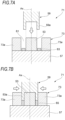
- FIGS. 6A and 6B are process explanatory diagrams showing a press molding process for molding a retainer.
- a press mold 51 shown in FIG. 6A includes a cylindrical inner mold 53, a cylindrical outer mold 55, a base mold 57, and a movable mold 59.
- the movable mold 59 includes an annular protrusion 59a.
- the inner mold 53 and the outer mold 55 are arranged concentrically about a central axis Ax, with one side surface in contact with the base mold 57.
- Each of the inner mold 53 and the outer mold 55 is fixed to the base mold 57 with fasteners such as bolts.
- a cylindrical clearance portion 61 is formed between an outer circumferential surface of the inner mold 53 and an inner circumferential surface of the outer mold 55.
- a preform 63 is set in the clearance portion 61 of the press mold.
- the outer circumferential surface of the inner mold 53 that defines the clearance portion 61 forms an inner diameter surface of the retainer
- the inner circumferential surface of the outer mold 55 forms an outer diameter surface of the retainer.
- the preform 63 is formed into an annular shape in the paper-making process before being placed in the press mold 51, and is placed in the clearance portion 61 which is an annular space larger than the annular shape of the preform 63.
- the press mold 51 is preheated by a heater, and the like (not shown) provided therein.
- the thermosetting resin 33 contained in the preform 63 can be brought into an easily flowable state during the subsequent thermosetting treatment.
- compressing is performed by applying pressure in the axial direction of the annular shape (direction of the central axis Ax) while constraining the inner diameter surface and the outer diameter surface of the preform 63.
- the movable mold 59 including the annular protrusion 59a fit in the clearance portion 61 is moved toward the base mold 57. Accordingly, the preform 63 is compressed in the direction of the central axis Ax.
- Constraining herein refers to a state in which the preform 63, which is placed in light contact or placed with a gap with the mold before compression molding, is gradually compressed into close contact as the preform 63 is compressed by the movable mold 59. In the process, it is sufficient that the thermosetting resin 33 of the preform 63 placed in the mold is in a flowable state, and it does not matter whether the preform 63 is heated or melted before molding.
- the preform 63 is heated within the press mold 51 to thermoset the thermosetting resin 33 contained in the preform 63.
- the heating of the preform 63 is a process of heating the press mold 51 to a temperature equal to or higher than the thermosetting start temperature of the thermosetting resin 33.
- the thermosetting conditions for the thermosetting resin 33 may be appropriately set according to the type of resin of the preform 63 to be used.
- the press mold 51 may be heated while the preform 63 is compression molded, and the press molding and thermosetting treatment may be performed at the same time. Here, tact time can be shortened.
- a compression molded body 65 is obtained by the compression molding and heat treatment described above.
- thermosetting treatment described above may be a post-curing process for the purpose of preventing dimensional shrinkage and improving mechanical properties during actual use of the retainer. Generally, adding the post-cure process improves the fatigue properties, tensile strength, and chemical resistance of the molded article.
- the thermosetting treatment described above may include a process of placing the preform 63 in a cavity of the mold, and injecting liquid resin into the cavity to perform resin molding.
- the compression molded body 65 after press molding and thermosetting treatment may be in the shape of the retainer, or the compression molded body 65 may be further machined into the shape of the retainer.
- the pockets 19a, 29a ( FIGS. 2 and 4 ), and the like of the retainers 19 and 29 can be formed by post-processing.
- any means such as machining, laser processing, water cutting, and the like can be employed as the means for forming the pockets.
- a slide core or the like may be provided in the press mold 51 to form the pockets at the same time as the press molding.
- the rolling bearings 11 and 21 shown in FIGS. 1 and 3 are assembled and produced using the retainer produced as described above.
- the retainer may be obtained by press molding and thermosetting treatment of a preform produced through a paper-making process. According to the method for producing the retainer, a retainer with high strength and high rigidity can be obtained, and a rolling bearing that can reduce damage to the retainer and achieve high reliability and long life can be obtained.
- FIGS. 7A and 7B are process explanatory diagrams showing another press molding process for molding the retainer.
- a press mold 71 shown in FIG. 7A is similar to the press mold 51 described above, except that an outer mold 73 is divided into a plurality of blocks 73a along the circumferential direction of the inner mold 53, and that each of the blocks 73a is changed to a slide core structure that is movable in the radial direction around the central axis Ax. Each of the blocks 73a moves radially in a plan view seen from the central axis Ax direction.
- the preform 63 is set in the cylindrical clearance portion 61 between the outer circumferential surface of the inner mold 53 and the inner circumferential surface of the outer mold 73. Then, the movable mold 59 is moved toward the base mold 57 by a drive mechanism (not shown) to fix the side surface of the preform 63. Then, as shown in FIG. 7B , the plurality of blocks 73a are moved radially inward by the drive mechanism (not shown) such that the preform 63 is press molded from the radially outer side toward the inner side.
- the press molding here is mainly performed by moving the plurality of blocks 73a in the radial direction, the press molding may also be performed by the movable mold 59 in cooperation with the press.
- the preform 63 is heated in the press mold 71, and the thermosetting resin 33 contained in the preform 63 is thermoset.
- the compression molded body 65 is obtained in the same manner as in the case described above.
- the gear box component will be described as a component of a gear box used in an electric power steering device, but the gear box component is not limited thereto and may be a component used in other devices.
- FIG. 8 is a schematic configuration diagram of the electric power steering device.
- An electric power steering device 100 transfers auxiliary output from an electric motor 111 to a steering mechanism 115 of a vehicle via a reduction gear mechanism 113. Note that the illustrated electric power steering device 100 is merely an example, and other types of mechanisms may be used.
- a steering shaft 117 with a steering wheel (not shown) fixed to its upper end is rotatably supported inside a steering shaft housing 119.
- the steering shaft housing 119 is fixed at a predetermined position inside the vehicle interior with its lower portion inclined toward the front of the vehicle.
- a rack and pinion mechanism 121 that converts the rotation of the steering shaft 117 into motion of the left and right steering wheels includes a rack 123 that is movable in the axial direction, a pinion shaft 125, and a cylindrical rack housing 127 that supports the rack 123 and the pinion shaft 125.
- the pinion shaft 125 is supported obliquely with respect to the axis of the rack 123 and includes a pinion provided with gear teeth that mesh with the gear teeth of the rack 123.
- the rack and pinion mechanism 121 is disposed substantially horizontally in an engine room at the front of the vehicle, with its longitudinal direction along the width direction of the vehicle.
- An upper end of the pinion shaft 125 and a lower end of the steering shaft 117 are connected with two universal joints 129 and 131.
- Steering wheels (not shown) are connected to both ends of the rack 123.
- the steering shaft 117 When the driver applies steering torque (rotational force) to the steering wheel, the steering shaft 117 is rotated, and the steering torque is detected by a torque sensor (not shown) attached to the steering shaft 117. Then, the output of the electric motor 111 (rotational force that assists steering) is controlled based on the detected steering torque.
- the output of the electric motor 111 is supplied to the intermediate portion of the steering shaft 117 via the reduction gear mechanism 113, combined with the steering torque, and converted by the rack and pinion mechanism 121 into a motion for steering the steering wheels.
- FIG. 9 is a partial cross-sectional view taken along a line IX-IX shown in FIG. 8
- FIG. 10 is a partial cross-sectional view taken along a line X-X shown in FIG. 9 .
- a gear box 133 that houses the reduction gear mechanism 113 of the electric power steering device 100 attached to the vehicle body includes, as the gear box components, a cylindrical gear box main body 135 having a bottom and a gear box cover 137 shown in FIG. 10 .
- the gear box cover 137 is fixed to the gear box main body 135 while covering an opening of the gear box main body 135. That is, bolts 139 are inserted into the opening provided on the gear box cover 137 side and fastened to screw holes provided on the gear box main body 135 side.
- the gear box 133 including the gear box main body 135 and the gear box cover 137 integrated by fastening the bolts 139 is obtained.
- an intermediate steering shaft 148 is rotatably supported by a first rolling bearing 151 and a second rolling bearing 153.
- the reduction gear mechanism 113, and a torque sensor 159 as a steering state detection sensor are housed inside the gear box 133.
- the reduction gear mechanism 113 includes a worm wheel 155 and a worm shaft 157 shown in FIG. 9 .
- the worm wheel 155 is fixed to an axially intermediate portion of the intermediate steering shaft 148 shown in FIG. 10 .
- the worm shaft 157 shown in FIG. 9 is connected to a rotating shaft 161 of the electric motor 111 via a spline joint 163, and meshes with the worm wheel 155.
- the worm wheel 155 includes a disk portion 155a rotatably fixed to the intermediate steering shaft 148, and synthetic resin teeth 155b formed on an outer diameter of the disk portion 155a.
- the intermediate steering shaft 148 is rotatably supported by the first rolling bearing 151 and the second rolling bearing 153 arranged on both sides of the worm wheel 155 in the axial direction.
- a torsion bar 167 is disposed passing through the axial centers of the steering shaft 117 and the intermediate steering shaft 148, a left end thereof in the drawing is fixed integrally with the intermediate steering shaft 148 by a connecting pin 169, and a right end thereof in the drawing is press-fit and fixed to the steering shaft 117.
- the worm shaft 157 that meshes with the worm wheel 155 is rotatably supported by a third rolling bearing 175 and a fourth rolling bearing 177 held by a gear housing 173.
- a proximal end of the worm shaft 157 is connected to the rotating shaft 161 of the electric motor 111 via the spline joint 163.
- the gear box 133 includes a plurality of gear box components including the gear box main body 135 and the gear box cover 137.
- Each of the gear box main body 135 and the gear box cover 137 is mainly configured to include a resin composition portion in which long fiber reinforcing fibers (fibrous filler) are dispersed in a resin material.
- the reinforcing fibers are contained in the resin material in a predetermined proportion according to the purpose of use. As a result, impact resistance, creep properties, rigidity, and dimensional stability are improved compared to when the gear box 133 is molded from a single resin material.
- the illustrated gear box 133 includes two portions, that is, the gear box main body 135 and the gear box cover 137, the present disclosure is not limited thereto, and other portions may be further combined.
- the other components may be a resin material containing the long fiber fibrous filler described above.
- the gear box main body 135 made of resin containing reinforcing fibers and the gear box cover 137 are integrated with each other by fastening with the bolts 139 to form the gear box 133.
- the fastening portion between the gear box main body 135 and the gear box cover 137 by the bolts 139 may be configured to insert-mold a core metal 143 on the side of the gear box main body 135 made of metal and a core metal 147 on the side of the gear box cover 137 made of metal, thereby fastening the embedded core metals 143 and 147 to each other.
- the gear box main body 135 may be configured to include a core metal 145 that fixes the first rolling bearing 151
- the gear box cover 137 may be configured to include a core metal 149 that fixes the second rolling bearing 153. Since the gear box 133 of the present configuration includes a resin composition portion, it is lighter than a related-art article made entirely of metal, and also has durability and reliability equivalent to that of the related-art article.
- Examples of the gear box main body 135 and gear box cover 137 including the core metals have structures schematically shown in FIGS. 11A and 11B .
- FIG. 11A is a plan view showing the gear box main body 135 as one unit including the core metal
- FIG. 11B is a plan view showing the gear box cover 137 as one unit including the core metal.
- the gear box main body 135 shown in FIG. 11A is provided with, integrally with a resin composition portion 141, the core metal 143 that is a fastening portion to the gear box cover 137 and a core metal 144 that is fit with the first rolling bearing 151.
- the gear box cover 137 shown in FIG. 11B is provided with, integrally with a resin composition portion 142, the core metal 145 that is a fastening portion to the gear box main body 135 and a core metal 146 that is fit with the second rolling bearing 153.
- the core metals 143, 144, 145, and 146 are integrally molded with the resin composition portions 141 and 142 as insert materials.
- the gear box main body 135 and the gear box cover 137 (hereinafter also referred to as gear box components) having the configuration described above are schematically produced as follows.
- reinforcing fibers having an average fiber length of 0.5 mm or more are opened in a solvent.
- a solvent for example, water can be used as the solvent.
- the reinforcing fibers and the resin (powder or fiber) described above are dispersed and mixed in the solvent to obtain a fiber containing slurry.
- This fiber containing slurry is dehydrated using a sheet- or paper-making mold to remove water (dry) and form a preform.
- a plurality of types of preforms (details will be described below) with different bulk densities of reinforcing fibers are prepared.
- the preform formed here is a reference density preform, and the reference density preform is further compression molded to obtain a high density preform.
- the preforms formed in each bulk density are set in a mold, and heated and cured if the resin dispersed and mixed in the preform is the thermosetting resin.
- the temperature at which the thermosetting resin is heated is not particularly limited, but may be appropriately selected within a temperature range at which impregnation and melting of the resin serving as the base material proceeds sufficiently and does not cause deterioration. As a result, a gear box component based on a fiber reinforced resin composition is obtained.
- thermosetting resin such as epoxy resin or phenol resin
- a reinforcing fiber such as glass fiber or carbon fiber
- thermoplastic resin By using thermosetting resin as the constituent material, a structure with excellent heat resistance and mechanical strength can be obtained.
- thermosetting resin as base resin and reinforcing fibers filled in the base resin.
- reinforcing fibers may include, but are not limited to, glass fibers, carbon fibers, metal fibers, aramid fibers, aromatic polyimide fibers, liquid crystal polyester fibers, silicon carbide fibers, alumina fibers, boron fibers, cellulose, cellulose nanofibers, and the like.
- the glass fibers and the boron fibers are preferred because of high tensile strength.
- the carbon fiber has excellent abrasion resistance, heat resistance, thermal elasticity, acid resistance, and electrical conductivity.
- metal threads of stainless steel, aluminum, iron, nickel, copper, and the like can be used.
- the aramid fibers have strong tensile strength and friction resistance and is also excellent in high temperature and chemical resistance.
- the aromatic polyamide fibers have excellent heat resistance and strength.
- Liquid crystal polyester fibers have a rigidity that exceeds that of filler-reinforced engineering plastics even in the unreinforced state.
- the alumina fibers can be used even in high temperature ranges and have fire resistance.
- the reinforcing fibers preferably have an average fiber length of 0.5 mm or more, more preferably 0.7 mm or more, and still more preferably 1 mm or more.
- the effect of improving impact resistance and dimensional stability is greater than when fibers with an average fiber length of less than 0.5 mm are added. Therefore, by setting the average fiber length to 0.5 mm or greater, the reinforcing effect of the resin material in the composite material may be reliably obtained.
- the amount of reinforcing fibers in the fiber reinforced resin composition is preferably 10 to 60% by mass.
- the amount of reinforcing fibers in the fiber reinforced resin composition is 10% by mass or more, higher durability than the related-art articles may be obtained.
- the amount of reinforcing fibers is 60% by mass or less, the toughness of the material is not impaired, and, for example, cold shock resistance is sufficient.
- the affinity between the resin material and the reinforcing fibers can be improved by treating the reinforcing fibers with a coupling agent such as a silane coupling agent or a titanate coupling agent.
- a coupling agent such as a silane coupling agent or a titanate coupling agent.
- the coupling agent is not limited to the silane coupling agent or the titanate coupling agent.
- additives may be added to the fiber reinforced resin composition within a range that does not impair the purpose of the present disclosure.
- the additive may include solid lubricants such as graphite, hexagonal boron nitride, fluorinated mica, tetrafluoroethylene resin powder, tungsten disulfide, and molybdenum disulfide, inorganic powders, organic powders, lubricating oils, plasticizer, rubber, antioxidant material, heat stabilizer, ultraviolet absorber, photoprotectant, flame retardant, antistatic agent, mold release agent, fluidity improver, thermal conductivity improver, non-tackifying agent, crystallization accelerator, nucleating agent, pigment, dye agent, and the like.
- solid lubricants such as graphite, hexagonal boron nitride, fluorinated mica, tetrafluoroethylene resin powder, tungsten disulfide, and molybdenum disulfide, inorganic powders, organic powders, lubricating oils, plasticizer
- a plurality of types of preforms with different bulk densities of reinforcing fibers having an average fiber length of 0.5 mm or more are integrally molded with a resin material and an insert material by press molding.
- a reference density preform formed with a reference bulk density and a high density preform formed with a bulk density higher than the reference density are used.
- the reference density preform has a bulk density (first bulk density) of 0.4 g/cm 3 or more and 1.0 g/cm 3 or less with reinforcing fibers with an average fiber length of 0.5 mm or more, and is set such that the minimum necessary strength may be obtained after resin molding.
- the high density preform is set to have a bulk density higher than the first bulk density described above, and preferably has a density that is 50% or more and 80% or less of the density of the molded article (resin composition excluding metal portions), for example.
- the reference density preform described above can be easily processed into various shapes, and thus can be formed into any shape according to the shape of the molded article.
- the high density preform can be molded by compressing the formed reference density preform, and thus improving strength.
- resin is dispersed and mixed between reinforcing fibers.
- the inside of the reference density preform and the high density preform is entirely and reliably impregnated with the resin during resin molding in the post-process.
- the high density preforms are selectively provided in portions of gear box components that require high strength. Accordingly, it is possible to have a high density of reinforcing fibers in portions requiring high strength and a relatively low density in the other regions, and locally adjust the strength of the molded article. As a result, it is possible to accurately provide different required strengths to different portions of the molded article, and it is also possible to reduce the amount of reinforcing fibers blended in portions where strength is not particularly required. It is possible to reduce the weight of the gear box components, and also achieve a structure that has the same durability and reliability as the related-art metal articles. Reinforcing fibers are not wasted, and an economically superior configuration can be achieved.
- a greater stress is likely to be generated in the resin composition portions 141 and 142 near the boundaries with the core metals 143, 144, 145, and 146 under the action of external force. Therefore, a configuration may be adopted in which the high density preforms are placed in areas including the boundaries with the core metals 143, 144, 145, and 146 in the resin composition portions 141 and 142, and the reference density preforms are placed in the other areas.
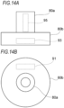
- FIGS. 12A and 12B are configuration diagrams of a molded article 80 imitating a gear box cover, in which FIG. 12A is an axial cross-sectional view and FIG. 12B is a plan view.
- the molded article 80 includes a shaft portion 80a and a flange portion 80b, and a large stress is generated in the shaft portion 80a.
- the high density preform is placed in the portion that is the shaft portion 80a of the mold
- the reference density preform is placed in the portion that is the flange portion 80b
- molding is performed by supplying resin into the cavity of the mold.
- the resin supplied into the cavity is preferably the same as the resin dispersed and mixed in the reference density preform and the high density preform, but may be substituted with other resins, or appropriate additives may be mixed therein.
- the high density preform and the reference density preform may be placed separately in the cavity, but it is also possible to integrate both preforms in advance to simplify the molding process.
- FIGS. 13A, 13B, and 13C are process explanatory diagrams showing a processing process of the integrated preform.
- a high density preform 85 is placed in a fixed side mold 83 at a portion corresponding to the shaft portion 80a ( FIGS. 12A and 12B ), and a reference density preform 87 is placed at a portion corresponding to the flange portion 80b.
- a movable side mold 89 is moved toward the fixed side mold 83 such that both molds are integrated together to approximate the shape of the molded article, thereby performing compression molding.
- FIG. 13C an integrated preform 90 in which the high density preform 85 and the reference density preform 87 are integrated in the mold is obtained.
- the obtained integrated preform 90 is taken out by opening the fixed side mold 83 and the movable side mold 89. Then, the integrated preform 90 taken out is placed in a cavity of a resin mold (not shown) and resin molded. As a result, the molded article 80 shown in FIGS. 12A and 12B is molded. Accordingly, the high density preform 85 and the reference density preform 87 can be handled integrally, so that handling performance is improved and workability of the molding process can be improved.
- the integrated preform 90 may be resin molded without being removed from the fixed side mold 83 and the movable side mold 89 and supplying resin into the cavity in the mold. That is, the mold for forming the integrated preform 90 may be used as the mold for resin molding to simplify the molding process.
- the method for producing the gear box components forming a gear box that houses a gear mechanism includes the following processes.
- the gear box component of the present configuration includes a portion provided with the high density preform and a portion provided with the reference preform, and in the portion provided with the high density preform, the density of reinforcing fibers can be increased compared to the other portions, thereby improving the impact resistance, creep properties, and rigidity of the molded article. It is possible to achieve weight reduction compared to related-art metal gear box components. When molding is performed using only the reference density preform, the reinforcing fibers flow during molding, causing disturbance in the orientation direction, and the strength is likely to decrease.
- the reinforcing fibers do not flow during molding, the strength of the molded article is increased, but the reinforcing fibers may not be filled at the ends of the product. Therefore, by combining the high density preform and the reference density preform, the reinforcing fibers are filled up to the ends of the molded article with the reference density preform, while the strength of the molded article is maintained with the high density preform, resulting in a configuration in which the reinforcing fibers are dispersed throughout the molded article.
- the molded article By joining the high density preform to the insert material and disposing the same in the cavity, it is possible to selectively improve the strength of the region including the boundary with the insert material. When a large external force is applied to the portion of the insert material of the molded article, the molded article can be configured with excellent high strength.
- the gear box main body 135 and the gear box cover 137 as shown in FIGS. 11A and 11B are produced by insert molding a resin material, using the core metals 143 and 145 of the fastening portion and the core metals 144 and 146 that fit into the first rolling bearing 151 and the second rolling bearing 153 as cores. As a result, the dimensional stability of the molded article is improved.
- the fixing strength of both the gear box main body 135 and the gear box cover 137 may be increased. Since the gear box main body 135 and the gear box cover 137 can be fastened together with bolts in the same way as when the gear box components are made of metal, it is possible to implement weight reduction and obtain durability and reliability equivalent to the related-art articles.
- the metal core and the inner and outer rings of the rolling bearing can be bonded to each other with sufficient reliability even without having to be subjected to surface roughening treatment.
- the desired strong adhesive state may be obtained.
- a high strength gear box component is obtained, which is formed by incorporating reinforcing fibers having an average fiber length of 0.5 mm or more in a resin material at a bulk density corresponding to the required strength.
- a preform impregnated with a certain amount of resin in advance is placed in the cavity of the mold, and then the resin molding process is performed in which molten resin is injected into the cavity and pressurized.
- a skin layer having a smooth surface and is made of resin that envelops reinforcing fibers is formed on the surface of the molded article.
- the method for producing described above can be suitably used to produce a retainer, for example, and can easily form a guide surface with high strength and high dimensional accuracy.
- the retainer 19 shown in FIG. 2 it is preferable to apply a high density preform to the annular portion 19A of the retainer 19, and apply a reference density preform to the columnar portions 19B.
- the specific producing process includes the following processes.
- an annular high density preform corresponding to the annular portion 19A and a columnar reference density preform corresponding to the columnar portion 19B are formed by the paper-making process described above.
- the obtained high density preform is placed in the cavity of the mold at a portion where the annular portion 19A is to be molded, and the reference density preform is placed in the cavity at a portion where the columnar portion 19B is to be molded. After the mold is clamped and heated, molten resin is injected into the cavity.
- the annular portion 19A including the high density preform and the columnar portion 19B including the reference density preform are integrated to obtain a retainer made of a resin impregnated composite material molded article.
- a skin layer is formed on the surface of the retainer.
- the annular portion 19A is formed with high strength and high precision, so that it is suitable as a retainer of an outer ring guide type or an inner ring guide type. Since the columnar portion 19B has more flexibility than the annular portion 19A, it is easier to insert the rolling element (roller) into the pocket.
- the high density preform and the low density preform may be separately formed, but it is also possible to form the entire retainer shape with the low density preform first, and then selectively compressing portions corresponding to the annular portion 19A into the high density preform.
- the portion corresponding to the annular portion 19A may be formed with the low density preform with a larger size considering compression and compressed to a desired size.
- the composite material molded article described above is not limited to the retainer, but any cylindrical or annular article can be molded in the same manner as described above.
- a member having an outer circumferential surface of a corresponding shape can be easily fit to the inner circumferential surface of the molded article.
- a hole into which the outer circumferential surface of the outer ring of the rolling bearing is fit can be formed in the housing with high strength and high precision.
- the preforms were placed in the cavity of the mold, and then a molten resin material was injected into the cavity and press molded together with the preforms to prepare a molded article.
- a molten resin material was injected into the cavity and press molded together with the preform. As such, a molded article was prepared.
- test Examples 1 and 2 carbon fibers with an average fiber length of 5.0 mm were used as reinforcing fibers, and phenol resin was used as the resin material.
- the high density preform was formed by wrapping the reference density preform around a rod and compressing the preform in the radial direction toward the rod using two half molds obtained by dividing the cylindrical shape into two. The temperature during compression was adjusted to not exceed the curing temperature of the resin. Thereafter, the resin was cured by heating.
- test pieces are cut out from each portion of a plane portion 91 including the upper surface of the flange portion 80b, a side portion 93 including the side surface of the flange portion 80b, and a cylindrical portion 95 on the side surface of the shaft portion 80a shown in FIGS. 14A and 14B , and a bending test was conducted on each test piece.
- the test results are shown in Table 1. Note that the bending test is a test method based on ISO178 (JIS K7171). [Table 1] Plane portion Side portion Cylindrical portion Bending strength [MPa] Test Ex. 1 440 480 430 Test Ex. 2 450 430 170
- a method for producing a retainer for use in a rolling bearing including processes of:
- the method for producing the retainer by press molding the preform formed by paper-making to form the retainer, it is possible to maintain a good lubrication condition even when used in a high speed rotation environment, thereby achieving high reliability and long life.
- (A2) The method according to (A1), in which the reinforcing fiber is at least one selected from carbon fiber, aramid fiber, glass fiber, cellulose fiber, polyarylate fiber, and polyparaphenylene benzbisoxazal fiber.
- the reinforcing properties of the reinforcing fibers can be ensured.
- the mechanical strength can be significantly improved, and the desired strength and rigidity can be ensured without impairing the toughness of the material.
- thermosetting resin is at least one selected from epoxy resin, bismaleimide resin, polyaminoamide resin, polyimide resin, and phenol resin.
- the retainer can be easily cured by thermosetting treatment.
- thermosetting resin in powder form.
- thermosetting resin According to the method for producing the retainer, reinforcing fibers and thermosetting resin can be sufficiently dispersed and mixed in the paper-making process.
- the preform can be press molded from the radially outer side to the radially inner side.
- (A7) A method for producing a rolling bearing, including producing a rolling bearing using the retainer produced by the method for producing the retainer according to any one of (A1) to (A6).
- the method for producing the rolling bearing it is possible to improve reliability and achieve a long life while maintaining good lubrication even when the rolling bearing is used in a high speed rotation environment.
- (B 1) A method for producing a gear box component forming a gear box that houses a gear mechanism, including processes of:
- the gear box component including a portion provided with the high density preform and a portion provided with the reference preform is molded.
- the high density preform is placed in a region where particularly high strength is required, such that the density of the reinforcing fibers may increase compared to the other regions. Therefore, excellent properties such as impact resistance, creep properties, rigidity, and dimensional stability can be obtained, and weight reduction can be achieved compared to the gear box component made of metal.
- the minimum necessary strength can be maintained.
- the resin is mixed in the reference preform and the high density preform in advance, it is possible to reliably impregnate the inside of the preform with the resin.
- (B4) The method according to any one of (B 1) to (B3), further including a process of integrally compression molding the reference preform and the high density preform before filling the mold with the resin.
- the reference preform and the high density preform are integrated, so the preforms are joined without any gaps, and the reinforcing fibers can be uniformly distributed.
- handling performance of the preform can be improved, and the workability of the molding process can be improved.
- the reference preform can be easily processed into various shapes during compression molding, gear boxes with various shapes can be produced.
- reinforcing fibers include at least one of carbon fibers, glass fibers, and aramid fibers.
- the gear box component can be made into a lightweight and high strength component.
- the gear box component can be made into a component with excellent heat resistance and creep properties such as bending and distortion.
- thermoplastic resin composition containing 10 to 60% by mass of the reinforcing fibers is formed by the resin molding.
- the high density preform is provided in contact with the insert material, thereby selectively increasing the density of reinforcing fibers around the insert material, and increasing the strength after molding.
- gear box component is a component forming a gear box that houses a reduction gear mechanism in an electric power steering device that transfers auxiliary output from an electric motor to a steering mechanism of a vehicle via the reduction gear mechanism.
- the method for producing the gear box component it is possible to obtain a gear box for an electric power steering device that is lightweight and has durability and reliability equivalent to those made of metal.
Landscapes
- Engineering & Computer Science (AREA)
- Mechanical Engineering (AREA)
- General Engineering & Computer Science (AREA)
- Chemical & Material Sciences (AREA)
- Composite Materials (AREA)
- Textile Engineering (AREA)
- Rolling Contact Bearings (AREA)
- Gears, Cams (AREA)
- Power Steering Mechanism (AREA)
- Casting Or Compression Moulding Of Plastics Or The Like (AREA)
- Moulding By Coating Moulds (AREA)
Applications Claiming Priority (3)
| Application Number | Priority Date | Filing Date | Title |
|---|---|---|---|
| JP2021082611 | 2021-05-14 | ||
| JP2022071024 | 2022-04-22 | ||
| PCT/JP2022/020276 WO2022239869A1 (ja) | 2021-05-14 | 2022-05-13 | 複合材料成形品の製造方法、保持器及び転がり軸受の製造方法、並びにギヤボックス構成部品の製造方法 |
Publications (2)
| Publication Number | Publication Date |
|---|---|
| EP4338941A1 true EP4338941A1 (de) | 2024-03-20 |
| EP4338941A4 EP4338941A4 (de) | 2024-12-25 |
Family
ID=84028390
Family Applications (1)
| Application Number | Title | Priority Date | Filing Date |
|---|---|---|---|
| EP22807567.7A Pending EP4338941A4 (de) | 2021-05-14 | 2022-05-13 | Verfahren zur herstellung eines verbundstoffmaterialformartikels, verfahren zur herstellung einer halterung und eines wälzlagers und verfahren zur herstellung einer getriebebestandteils |
Country Status (4)
| Country | Link |
|---|---|
| US (1) | US20240269946A1 (de) |
| EP (1) | EP4338941A4 (de) |
| JP (1) | JP7302753B2 (de) |
| WO (1) | WO2022239869A1 (de) |
Families Citing this family (2)
| Publication number | Priority date | Publication date | Assignee | Title |
|---|---|---|---|---|
| KR20250118540A (ko) * | 2024-01-30 | 2025-08-06 | 현대자동차주식회사 | 플라스틱 복합소재 부품 성형 장치 |
| JP2026063979A (ja) * | 2024-10-01 | 2026-04-13 | 株式会社レゾナック | 成形体及び樹脂ギヤ |
Family Cites Families (18)
| Publication number | Priority date | Publication date | Assignee | Title |
|---|---|---|---|---|
| JPS6015460B2 (ja) * | 1980-10-17 | 1985-04-19 | 日立化成工業株式会社 | 成形管の製造方法 |
| JP4026323B2 (ja) * | 2000-07-12 | 2007-12-26 | 新神戸電機株式会社 | 樹脂製歯車用成形体の製造法及び樹脂製歯車の製造法 |
| JP2005193587A (ja) * | 2004-01-09 | 2005-07-21 | Toray Ind Inc | Rtm成形方法 |
| JP5163105B2 (ja) * | 2007-12-25 | 2013-03-13 | 新神戸電機株式会社 | 樹脂製回転体及びその製造方法、樹脂製回転体成形用半加工品及びその製造方法並びに補強用繊維基材成形用金型 |
| JP2009298246A (ja) | 2008-06-11 | 2009-12-24 | Jtekt Corp | 電動パワーステアリング装置 |
| JP2010115853A (ja) * | 2008-11-13 | 2010-05-27 | Shin Kobe Electric Mach Co Ltd | 樹脂製回転体成形用半加工品の製造方法及び樹脂製回転体の製造方法ならびに樹脂製歯車 |
| JP2012020647A (ja) | 2010-07-14 | 2012-02-02 | Jtekt Corp | 電動パワーステアリング装置 |
| JP6229881B2 (ja) * | 2013-11-14 | 2017-11-15 | 株式会社ジェイテクト | 繊維強化複合成形品の製造方法 |
| JP2015135153A (ja) | 2014-01-17 | 2015-07-27 | Ntn株式会社 | 転がり軸受用保持器およびその製造方法、並びに転がり軸受 |
| JP2015232382A (ja) | 2014-06-11 | 2015-12-24 | Ntn株式会社 | 転がり軸受用保持器および転がり軸受 |
| JP2016121754A (ja) * | 2014-12-25 | 2016-07-07 | 日本精工株式会社 | 転がり軸受用樹脂製保持器及びその製造方法 |
| CN108431099B (zh) * | 2015-12-25 | 2021-04-27 | 东丽株式会社 | 结构体 |
| JP6365798B1 (ja) * | 2016-09-21 | 2018-08-01 | 住友ベークライト株式会社 | 複合成形体および複合成形体の製造方法 |
| JP7244691B2 (ja) | 2018-02-27 | 2023-03-22 | 株式会社ジャパンディスプレイ | 表示装置 |
| JP7056431B2 (ja) * | 2018-07-19 | 2022-04-19 | 日本精工株式会社 | ギヤボックス構成部品の製造方法、及びギヤボックス構成部品のプリフォームの製造方法 |
| JP2020028984A (ja) * | 2018-08-20 | 2020-02-27 | 旭化成株式会社 | フィラメントワインディング(fw)法によるudライクな閉じた繊維強化複合成形体及びその製造方法の提供 |
| JP7310421B2 (ja) * | 2019-08-02 | 2023-07-19 | 住友ベークライト株式会社 | 複合成形体 |
| JP7036965B2 (ja) | 2021-03-04 | 2022-03-15 | 日立グローバルライフソリューションズ株式会社 | 照明装置 |
-
2022
- 2022-05-13 EP EP22807567.7A patent/EP4338941A4/de active Pending
- 2022-05-13 WO PCT/JP2022/020276 patent/WO2022239869A1/ja not_active Ceased
- 2022-05-13 JP JP2022554737A patent/JP7302753B2/ja active Active
- 2022-05-13 US US18/290,393 patent/US20240269946A1/en active Pending
Also Published As
| Publication number | Publication date |
|---|---|
| JPWO2022239869A1 (de) | 2022-11-17 |
| US20240269946A1 (en) | 2024-08-15 |
| EP4338941A4 (de) | 2024-12-25 |
| WO2022239869A1 (ja) | 2022-11-17 |
| JP7302753B2 (ja) | 2023-07-04 |
Similar Documents
| Publication | Publication Date | Title |
|---|---|---|
| Zhang et al. | Recent progress of 3D printed continuous fiber reinforced polymer composites based on fused deposition modeling: a review | |
| EP4338941A1 (de) | Verfahren zur herstellung eines verbundstoffmaterialformartikels, verfahren zur herstellung einer halterung und eines wälzlagers und verfahren zur herstellung einer getriebebestandteils | |
| WO1995028267A1 (en) | A polymeric based composite bearing | |
| Koch et al. | Lightweight design and manufacturing of composites for high-performance electric motors | |
| EP2623802A1 (de) | Halter für ein wälzlager und wälzlager | |
| WO1995028267A9 (en) | A polymeric based composite bearing | |
| EP3372855B1 (de) | Gleitelement | |
| EP3029105B1 (de) | Wärmehärtbare harzzusammensetzung, gleitelement und verfahren zur herstellung des gleitelements | |
| CN102705410A (zh) | 一种复合摩擦片及其制备方法 | |
| US9267542B2 (en) | System of sliding elements | |
| KR100803055B1 (ko) | 구면베어링 조립체의 제조장치 및 그 제조방법 | |
| CN105524405A (zh) | 抗静电peek复合材料及其制备方法 | |
| CN107035794A (zh) | 背板用组合物、背板、制动片和卡钳装置 | |
| US20240084707A1 (en) | Fiber Reinforced Polymer Blade | |
| EP0470155B1 (de) | Verschleissfeste mehrschichtige gegenstände | |
| JP2012132535A (ja) | 転がり軸受用保持器及び転がり軸受 | |
| JP7056431B2 (ja) | ギヤボックス構成部品の製造方法、及びギヤボックス構成部品のプリフォームの製造方法 | |
| US20150219156A1 (en) | Multilayer sliding member and method for manufacturing multilayer sliding members | |
| JP5120098B2 (ja) | 高速回転用転がり軸受 | |
| EP2955401B1 (de) | Gleitlager | |
| EP2955399B1 (de) | Gleitlager | |
| CN117425558A (zh) | 复合材料成形品的制造方法、保持架及滚动轴承的制造方法、以及齿轮箱构成部件的制造方法 | |
| WO2015108141A1 (ja) | 転がり軸受用保持器およびその製造方法、並びに転がり軸受 | |
| EP3189124B1 (de) | Verbundlager mit verbesserter verschleissbeständigkeit und bearbeitbarkeit | |
| KR101346267B1 (ko) | 기어펌프용 플라스틱 기어의 제조방법 |
Legal Events
| Date | Code | Title | Description |
|---|---|---|---|
| STAA | Information on the status of an ep patent application or granted ep patent |
Free format text: STATUS: THE INTERNATIONAL PUBLICATION HAS BEEN MADE |
|
| PUAI | Public reference made under article 153(3) epc to a published international application that has entered the european phase |
Free format text: ORIGINAL CODE: 0009012 |
|
| STAA | Information on the status of an ep patent application or granted ep patent |
Free format text: STATUS: REQUEST FOR EXAMINATION WAS MADE |
|
| 17P | Request for examination filed |
Effective date: 20231114 |
|
| AK | Designated contracting states |
Kind code of ref document: A1 Designated state(s): AL AT BE BG CH CY CZ DE DK EE ES FI FR GB GR HR HU IE IS IT LI LT LU LV MC MK MT NL NO PL PT RO RS SE SI SK SM TR |
|
| DAV | Request for validation of the european patent (deleted) | ||
| DAX | Request for extension of the european patent (deleted) | ||
| A4 | Supplementary search report drawn up and despatched |
Effective date: 20241125 |
|
| RIC1 | Information provided on ipc code assigned before grant |
Ipc: B29C 70/86 20060101ALI20241119BHEP Ipc: B29C 70/48 20060101ALI20241119BHEP Ipc: B29B 11/16 20060101ALI20241119BHEP Ipc: F16H 57/032 20120101ALI20241119BHEP Ipc: F16C 19/00 20060101ALI20241119BHEP Ipc: B62D 5/04 20060101ALI20241119BHEP Ipc: B29C 70/68 20060101ALI20241119BHEP Ipc: B29C 70/12 20060101ALI20241119BHEP Ipc: B29C 43/34 20060101ALI20241119BHEP Ipc: B29C 43/18 20060101ALI20241119BHEP Ipc: B29C 70/46 20060101AFI20241119BHEP |