EP4338967B1 - Tintenaufbereiter für einen tintenstrahldrucker - Google Patents
Tintenaufbereiter für einen tintenstrahldrucker Download PDFInfo
- Publication number
- EP4338967B1 EP4338967B1 EP22195679.0A EP22195679A EP4338967B1 EP 4338967 B1 EP4338967 B1 EP 4338967B1 EP 22195679 A EP22195679 A EP 22195679A EP 4338967 B1 EP4338967 B1 EP 4338967B1
- Authority
- EP
- European Patent Office
- Prior art keywords
- ink
- conditioner
- conditioner according
- main body
- heat transfer
- Prior art date
- Legal status (The legal status is an assumption and is not a legal conclusion. Google has not performed a legal analysis and makes no representation as to the accuracy of the status listed.)
- Active
Links
Images


Classifications
-
- B—PERFORMING OPERATIONS; TRANSPORTING
- B41—PRINTING; LINING MACHINES; TYPEWRITERS; STAMPS
- B41J—TYPEWRITERS; SELECTIVE PRINTING MECHANISMS, i.e. MECHANISMS PRINTING OTHERWISE THAN FROM A FORME; CORRECTION OF TYPOGRAPHICAL ERRORS
- B41J2/00—Typewriters or selective printing mechanisms characterised by the printing or marking process for which they are designed
- B41J2/005—Typewriters or selective printing mechanisms characterised by the printing or marking process for which they are designed characterised by bringing liquid or particles selectively into contact with a printing material
- B41J2/01—Ink jet
- B41J2/17—Ink jet characterised by ink handling
- B41J2/175—Ink supply systems ; Circuit parts therefor
- B41J2/17596—Ink pumps, ink valves
-
- B—PERFORMING OPERATIONS; TRANSPORTING
- B41—PRINTING; LINING MACHINES; TYPEWRITERS; STAMPS
- B41J—TYPEWRITERS; SELECTIVE PRINTING MECHANISMS, i.e. MECHANISMS PRINTING OTHERWISE THAN FROM A FORME; CORRECTION OF TYPOGRAPHICAL ERRORS
- B41J2/00—Typewriters or selective printing mechanisms characterised by the printing or marking process for which they are designed
- B41J2/005—Typewriters or selective printing mechanisms characterised by the printing or marking process for which they are designed characterised by bringing liquid or particles selectively into contact with a printing material
- B41J2/01—Ink jet
- B41J2/17—Ink jet characterised by ink handling
- B41J2/175—Ink supply systems ; Circuit parts therefor
-
- B—PERFORMING OPERATIONS; TRANSPORTING
- B41—PRINTING; LINING MACHINES; TYPEWRITERS; STAMPS
- B41J—TYPEWRITERS; SELECTIVE PRINTING MECHANISMS, i.e. MECHANISMS PRINTING OTHERWISE THAN FROM A FORME; CORRECTION OF TYPOGRAPHICAL ERRORS
- B41J2/00—Typewriters or selective printing mechanisms characterised by the printing or marking process for which they are designed
- B41J2/005—Typewriters or selective printing mechanisms characterised by the printing or marking process for which they are designed characterised by bringing liquid or particles selectively into contact with a printing material
- B41J2/01—Ink jet
- B41J2/17—Ink jet characterised by ink handling
- B41J2/18—Ink recirculation systems
-
- B—PERFORMING OPERATIONS; TRANSPORTING
- B41—PRINTING; LINING MACHINES; TYPEWRITERS; STAMPS
- B41J—TYPEWRITERS; SELECTIVE PRINTING MECHANISMS, i.e. MECHANISMS PRINTING OTHERWISE THAN FROM A FORME; CORRECTION OF TYPOGRAPHICAL ERRORS
- B41J2/00—Typewriters or selective printing mechanisms characterised by the printing or marking process for which they are designed
- B41J2/005—Typewriters or selective printing mechanisms characterised by the printing or marking process for which they are designed characterised by bringing liquid or particles selectively into contact with a printing material
- B41J2/01—Ink jet
- B41J2/17—Ink jet characterised by ink handling
- B41J2/195—Ink jet characterised by ink handling for monitoring ink quality
Definitions
- the invention relates to an ink conditioner for an inkjet printer.
- Inkjet printers are typically used to digitally print various products, such as labels, textiles, ceramic tiles and many more, by dispensing small ink droplets through nozzles of a printing head.
- the ink parameters such as the ink viscosity, the ink flow rate and the ink pressure, have to be controlled precisely. If the ink viscosity is too high and/or the ink meniscus pressure too low, the ink might not be able to exit the printing head nozzles. In contrast, a too low ink viscosity or a too high meniscus pressure may result in formation of satellite droplets and overall lower print quality. Furthermore, when performing inkjet printing on porous substrates, the resulting printing dot is influenced by viscosity dependent spreading of the ink on the substrate and penetration of the ink into the substrate.
- the ink control is often complex and requires a sophisticated ink management system with a manifold that distributes the ink to the single print heads and/or controls the ink temperature such that a desired viscosity is reached.
- ink conditioners are applied that enable precise control of the ink parameters directly at the print head inlet and/or outlet.
- Such ink conditioners may comprise means for measuring and adjusting the ink pressure, means for measuring and adjusting the ink temperature, means for flushing the print head, means for circulating ink through the print head and means for damping vibrations in the ink and/or evening out variations in the ink flow velocity and/or ink pressure that may be caused by ink circulation pumps.
- Ink conditioners known from the state of the art typically comprise a plurality of different parts, such as hoses, connectors and seals that are made from different materials and assembled together. As a result, the conditioners are prone to errors and/or disturbances, such as sealing leakage or clogging caused by formation of ink deposits, which can appear if the ink is incompatible with one of the materials the conditioner consists of.
- US-A-2022/0203689 discloses the preamble of claim 1.
- the object of the invention is to provide an ink conditioner for an inkjet printer that is less prone to such errors and/or disturbances and thus improves the stability of the printing process.
- an ink conditioner for an inkjet printer comprising a main body with an ink damping cavity, the ink conditioner further comprising a heat transfer element, at least one ink inlet and at least one ink outlet, wherein the main body, the heat transfer element, the at least one ink inlet and the at least one ink outlet consist of the same material and form a single piece.
- inlet refers to openings through which a liquid can enter the conditioner.
- outlet refers to openings through which a liquid can leave the conditioner.
- the heat transfer element can be used for adjusting the ink temperature.
- the proposed conditioner structure with the different conditioner elements forming a single piece from the same material reduces the effort for assembling the conditioner. Furthermore, compared to conventional conditioners, the total number of applied individual parts and materials and thus potential points of failure is reduced.
- the rapid prototyping and/or 3D printing technique enables to manufacture the main elements of the conditioner in a single time and cost saving processing step, even if the conditioner geometry is complex.
- the main body, the heat transfer element, the at least one ink inlet and the at least one ink outlet consist of titanium.
- This metal offers high hardness and excellent corrosion resistivity.
- titanium is antimagnetic and therefore not prone to interfere with electronic parts.
- the ink conditioner comprises a membrane for sealing the ink damping cavity and a spring plate, wherein the membrane is located between the main body and the spring plate.
- the membrane is elastically deformable. If the ink pressure within the ink damping cavity fluctuates, the membrane may deflect in- and/or outwardly, such that the pressure fluctuations are damped.
- the spring plate stabilizes the membrane and limits the maximum deflection.
- the ink damping cavity has a circular shape. This allows to apply circular membranes for sealing the ink damping cavity. Due to the circular shape, the membranes deform symmetrically. This enables damping in comparably high pressure ranges and improves the process control in general.
- the main body can comprise at least one linear channel with an opening inside the ink damping cavity in which a spring plate guiding element can be placed.
- the spring plate guidance element can be spring mounted piston pressing against the spring plate to ensure accurate and smooth spring plate movement.
- the heat transfer element comprises a cavity configured to receive a heating element and an ink channel surrounding the cavity. This enables heating of the ink without a direct contact between the ink and the heating element.
- the ink channel comprises an ink outlet configured to be directly connected to an inlet of a print head.
- the arrangement close to the print head increases the accuracy of the printing temperature control. Deviations between set temperature and actual printing temperature are prevented or at least minimized by the short flow path between sensor and print head.
- the conditioner comprises a first pressure sensor configured to measure an ink pressure in a first pressure range inside of the ink channel and a second pressure sensor configured to measure an ink pressure in a second pressure range inside of the ink channel.
- the first pressure sensor may be configured to accurately measure low ink pressures up to 50 mbar.
- the second pressure sensor may be configured to measure high pressures up to 1 bar. This improves the overall accuracy of the ink pressure measurement and/or control over the whole application relevant pressure range.
- the ink conditioner can comprise a connection zone configured to receive a screw or bolt for connecting the ink conditioner directly to a print head. This facilitates the assembly. Furthermore, a rigid connection between conditioner and print head can be formed, which reduces the risk of leakage at the interface between both parts.
- the conditioner comprises a valve for print head flushing. This enables fast and easy cleaning of the print head, for example to recover blocked nozzles, without the necessity to disassemble the printer and/or print unit.
- Figure 1 schematically shows a side view of a printing unit 10 for an industrial single pass inkjet printer. It is conceivable that the inkjet printer is equipped with multiple such printing units 10, which form a stack that defines the print width of the printer.
- the printing unit 10 comprises a manifold 12, four ink conditioners 14 and four piezoelectric inkjet print heads 16, for example Dimatix Samba print heads with a plurality of individually addressable nozzles arranged on a trapezoidal nozzle plate.
- Each conditioner 14 corresponds to an individual print head 16.
- the manifold 12 comprises means to control the ink temperature, such as a main body 18 with an ink cavity 20 in thermal contact with a temperature control fluid cavity 22, as well as means to distribute the ink to the individual conditioners 14, in particular multiple inlets and outlets for the ink.
- Fig. 2 shows a schematic 3D illustration of an ink conditioner 14 according to the invention, which is adapted to receive ink from the manifold 12.
- the conditioner 14 comprises a main body 18 with a circular ink damping cavity 24, in particular for damping circulation pump induced pressure fluctuations within the ink.
- the conditioner 14 further comprises a heat transfer element 26 for fine adjustment of the ink temperature, two ink inlets 28 through which ink can enter the conditioner 14, in particular a main ink inlet 30 and an ink return inlet 32, and two ink outlets 34 through which ink can leave the conditioner 14, in particular a main ink outlet 36 and a print head feed outlet 38.
- the described conditioner 14 further comprises a connection zone 40 configured to receive a screw or bolt for connecting the ink conditioner 14 directly to a print head 16.
- the main body 18, the heat transfer element 26, the ink inlets 28, the ink outlets 34 and the connection zone 40 form a single piece and consist of 3D printed titanium.
- FIG. 3 A schematic 3D illustration of this single piece is shown in figure 3 .
- the single piece can comprise further elements, such as liquid inlets, for example a flush inlet 42 through which a flushing liquid for print head cleaning can enter the conditioner 14.
- liquid inlets for example a flush inlet 42 through which a flushing liquid for print head cleaning can enter the conditioner 14.
- the single piece additionally comprises three linear channels 44 with openings 46 inside the ink damping cavity 24 for receiving movable parts, in particular guiding elements.
- the single piece does not comprise any sealing or similar parts made from rubber or comparable materials. It is thus very robust and due to the inert nature of the titanium surface highly compatible with many different types of inks, in particular inks containing polar and/or nonpolar and/or organic solvents.
- the conditioner 14 contains a plurality of further parts mounted to the 3D printed titanium structure.
- Figure 4 shows an explosion drawing of these ink conditioner parts, including a circulation pump 48, a valve 50 for regulating the liquid flow through the print head feed outlet 38, a valve 52 that allows print head flushing, a sealed circuit board 54, in particular for controlling the circulation pump 48 and/or the valves 50, 52.
- the circulation pump 48 is located between the ink return inlet 32 and the main ink outlet 36. Consequently, the circulating ink flows through the print head 16 before it passes the circulation pump 48.
- the manifold 12 forms part of the ink circulation system.
- the circulation pump 48 may generate an ink flow from the manifold 12 to the conditioner 14, from the conditioner 14 to the print head 16, from the print head 16 to the conditioner 14 and from the conditioner 14 back to the manifold 12.
- the valve 50 can regulate and/or interrupt the ink circulation, for example if print head cleaning and/or flushing is intended.
- the ink conditioner 14 further comprises a circular membrane 56 for sealing the ink damping cavity 24, a spring plate 58 and spring plate guiding elements 60.
- Fig. 5 shows a first cross section of the assembled conditioner 14, in particular of the ink damping cavity 24 and corresponding parts.
- the membrane 56 is elastically deformable and located between the main body 18 and the spring plate 58. If the ink pressure within the ink damping cavity 24 fluctuates, the membrane 56 may symmetrically deform and/or deflect towards and/or away from the main body 18, thereby changing the cavity volume such that the pressure fluctuations are damped.
- the spring plate 58 stabilizes the membrane 56 during deflection and limits it's maximum travel.
- the spring plate guiding elements 60 are spring mounted pistons, which are movably seated in the linear channels 44 of the main body 18. Due to the spring mounting, the spring plate guiding elements 60 press against the membrane 56 and/or spring plate 58, thereby ensuring accurate and smooth spring plate movement. It is conceivable that the damping characteristics of the ink damping cavity 24 depend on the Young's modulus of the mounting springs and/or of the spring plate 58.
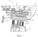
- Fig. 6 shows a second cross section of the assembled conditioner 14, in particular of heat transfer element 26.
- the heat transfer element 26 comprises a cavity in which a heating element 64, in particular a resistive heater, is located.
- the heat transfer element 26 further comprises an ink channel surrounding the heater cavity.
- the walls forming the heater cavity as well as the surrounding ink channel consist of 3D printed titanium with a high heat conduction coefficient. Heat generated by the heating element 64 is thus efficiently conducted towards the ink inside the ink channel.
- the ink channel comprises an ink outlet, in the embodiment the print head feed outlet 38, which is directly connected to an inlet of a print head 16. It is thus possible to adjust the ink temperature of the ink directly before it enters the print head 16.
- the conditioner 14 further comprises a first pressure sensor 68 configured to measure an ink pressure in a first pressure range inside of the ink channel and a second pressure sensor 70 configured to measure an ink pressure in a second pressure range inside of the ink channel.
Landscapes
- Engineering & Computer Science (AREA)
- Quality & Reliability (AREA)
- Ink Jet (AREA)
Claims (11)
- Tintenkonditionierer für einen Tintenstrahldrucker, der einen Hauptkörper (18) mit einem Tintendämpfungshohlraum (24) umfasst, wobei der Tintenkonditionierer (14) weiter ein Wärmeübertragungselement (26), mindestens einen Tinteneinlass (28) und mindestens einen Tintenauslass (34) umfasst,
dadurch gekennzeichnet, dass der Hauptkörper (18), das Wärmeübertragungselement (26), der mindestens eine Tinteneinlass (28) und der mindestens eine Tintenauslass (34) aus dem gleichen Material bestehen und ein einziges Stück bilden. - Tintenkonditionierer nach Anspruch 1, wobei der Hauptkörper (18), das Wärmeübertragungselement (26), der mindestens eine Tinteneinlass (28) und der mindestens eine Tintenauslass (34) aus einem 3D-gedruckten Metall bestehen.
- Tintenkonditionierer nach Anspruch 1 oder 2, wobei der Hauptkörper (18), das Wärmeübertragungselement (26), der mindestens eine Tinteneinlass (28) und der mindestens eine Tintenauslass (34) aus Titan bestehen.
- Tintenkonditionierer nach einem der vorstehenden Ansprüche, wobei der Tintendämpfungshohlraum (24) eine kreisförmige Form aufweist.
- Tintenkonditionierer nach einem der vorstehenden Ansprüche, der weiter eine Membran (56) zum Abdichten des Tintendämpfungshohlraums (24) und eine Federplatte (58) umfasst, wobei sich die Membran (56) zwischen dem Hauptkörper (18) und der Federplatte (58) befindet.
- Tintenkonditionierer nach einem der vorstehenden Ansprüche, wobei der Hauptkörper (18) mindestens einen linearen Kanal (44) mit einer Öffnung (46) innerhalb des Tintendämpfungshohlraums (24) umfasst, der zum Aufnehmen eines Federplattenführungselements (60) konfiguriert ist.
- Tintenkonditionierer nach einem der vorstehenden Ansprüche, wobei das Wärmeübertragungselement (26) einen Hohlraum, der zum Aufnehmen eines Heizelements (64) konfiguriert ist, und einen Tintenkanal, der den Hohlraum umgibt, umfasst.
- Tintenkonditionierer nach Anspruch 7, wobei der Tintenkanal einen Tintenauslass (34) umfasst, der so konfiguriert ist, dass er direkt mit einem Einlass eines Druckkopfs (16) verbunden werden kann.
- Tintenkonditionierer nach Anspruch 7 oder 8, der weiter einen ersten Drucksensor (68), der zum Messen eines Tintendrucks in einem ersten Druckbereich innerhalb des Tintenkanals konfiguriert ist, und einen zweiten Drucksensor (70), der zum Messen eines Tintendrucks in einem zweiten Druckbereich innerhalb des Tintenkanals konfiguriert ist, umfasst.
- Tintenkonditionierer nach einem der vorstehenden Ansprüche, der weiter eine Verbindungszone (40) umfasst, die zum Aufnehmen einer Schraube oder eines Bolzens zum direkten Verbinden des Tintenkonditionierers (14) mit einem Druckkopf (16) konfiguriert ist.
- Tintenkonditionierer nach einem der vorstehenden Ansprüche, der weiter ein Ventil (52) zum Druckkopfspülen umfasst.
Priority Applications (6)
| Application Number | Priority Date | Filing Date | Title |
|---|---|---|---|
| ES22195679T ES3018419T3 (es) | 2022-09-14 | 2022-09-14 | Acondicionador de tinta para impresora de inyección de tinta |
| EP22195679.0A EP4338967B1 (de) | 2022-09-14 | 2022-09-14 | Tintenaufbereiter für einen tintenstrahldrucker |
| CN202380051087.2A CN119486887A (zh) | 2022-09-14 | 2023-08-29 | 一种用于喷墨打印机的墨料调节器 |
| PCT/EP2023/073615 WO2024056363A1 (en) | 2022-09-14 | 2023-08-29 | Ink conditioner for an inkjet printer |
| JP2024576659A JP7808717B2 (ja) | 2022-09-14 | 2023-08-29 | インクジェット印刷機のためのインク調節器 |
| US18/874,204 US20250367939A1 (en) | 2022-09-14 | 2023-08-29 | Ink conditioner for an inkjet printer |
Applications Claiming Priority (1)
| Application Number | Priority Date | Filing Date | Title |
|---|---|---|---|
| EP22195679.0A EP4338967B1 (de) | 2022-09-14 | 2022-09-14 | Tintenaufbereiter für einen tintenstrahldrucker |
Publications (2)
| Publication Number | Publication Date |
|---|---|
| EP4338967A1 EP4338967A1 (de) | 2024-03-20 |
| EP4338967B1 true EP4338967B1 (de) | 2025-03-26 |
Family
ID=83318905
Family Applications (1)
| Application Number | Title | Priority Date | Filing Date |
|---|---|---|---|
| EP22195679.0A Active EP4338967B1 (de) | 2022-09-14 | 2022-09-14 | Tintenaufbereiter für einen tintenstrahldrucker |
Country Status (6)
| Country | Link |
|---|---|
| US (1) | US20250367939A1 (de) |
| EP (1) | EP4338967B1 (de) |
| JP (1) | JP7808717B2 (de) |
| CN (1) | CN119486887A (de) |
| ES (1) | ES3018419T3 (de) |
| WO (1) | WO2024056363A1 (de) |
Family Cites Families (5)
| Publication number | Priority date | Publication date | Assignee | Title |
|---|---|---|---|---|
| JP2002361864A (ja) * | 2001-06-11 | 2002-12-18 | Sii Printek Inc | インクジェットヘッド及びインクジェット式記録装置 |
| WO2010032984A2 (ko) * | 2008-09-22 | 2010-03-25 | Na Jong Kap | 잉크 점도 조절 장치 |
| JP2012218214A (ja) * | 2011-04-05 | 2012-11-12 | Sii Printek Inc | 液体噴射ヘッド及び液体噴射装置 |
| JP7031421B2 (ja) * | 2018-03-26 | 2022-03-08 | 京セラドキュメントソリューションズ株式会社 | 液体噴射装置 |
| EP4023445B1 (de) * | 2020-12-30 | 2024-08-21 | Dover Europe Sàrl | Tintenkreislauf mit mehreren modularen einheiten |
-
2022
- 2022-09-14 EP EP22195679.0A patent/EP4338967B1/de active Active
- 2022-09-14 ES ES22195679T patent/ES3018419T3/es active Active
-
2023
- 2023-08-29 JP JP2024576659A patent/JP7808717B2/ja active Active
- 2023-08-29 WO PCT/EP2023/073615 patent/WO2024056363A1/en not_active Ceased
- 2023-08-29 US US18/874,204 patent/US20250367939A1/en active Pending
- 2023-08-29 CN CN202380051087.2A patent/CN119486887A/zh active Pending
Also Published As
| Publication number | Publication date |
|---|---|
| EP4338967A1 (de) | 2024-03-20 |
| CN119486887A (zh) | 2025-02-18 |
| US20250367939A1 (en) | 2025-12-04 |
| JP2025520819A (ja) | 2025-07-03 |
| WO2024056363A1 (en) | 2024-03-21 |
| JP7808717B2 (ja) | 2026-01-29 |
| ES3018419T3 (es) | 2025-05-16 |
Similar Documents
| Publication | Publication Date | Title |
|---|---|---|
| EP1034931B1 (de) | Aufzeichnungskopf des Tintenstrahltyps | |
| EP1688260B1 (de) | Tintenzuführgerät und Tintenstrahldruckkopfsystem dafür | |
| EP1652672B1 (de) | Tintenstrahldruckkopf mit Hebelarmbetätiger | |
| EP2563597B1 (de) | Flüssigkeitsausstossvorrichtung | |
| US12059893B2 (en) | Piezoelectric droplet deposition apparatus optimised for high viscosity fluids, and methods and control system therefor | |
| JP4953884B2 (ja) | 記録ヘッド | |
| KR20170114926A (ko) | 잉크젯 프린트 헤드에서의 단일 분사 재순환 | |
| US5988786A (en) | Articulated stress relief of an orifice membrane | |
| EP4338967B1 (de) | Tintenaufbereiter für einen tintenstrahldrucker | |
| CN107618264B (zh) | 液体喷射方法、液体喷射装置以及液体喷射头 | |
| EP3536508B1 (de) | Druckkopf | |
| US10668725B2 (en) | Supply manifold in a printhead | |
| CN108367569A (zh) | 喷墨头以及喷墨记录装置 | |
| US12434482B2 (en) | Liquid ejection apparatus and head unit | |
| JP2011167881A (ja) | 液体噴射ヘッドおよび液体噴射装置 | |
| US8393723B2 (en) | Bubble purging system for a fluid ejection head | |
| JP2011207098A (ja) | インクジェットヘッド、インクジェット記録装置及びインクジェットヘッドの製造方法 | |
| US20020054191A1 (en) | Ink jet printer head and fabrication method for an ink jet printer head | |
| EP4338966B1 (de) | Verteiler für einen tintenstrahldrucker | |
| US12539702B2 (en) | Inkjet print head with continuous flow and improved temperature uniformity | |
| JP2011167854A (ja) | 液体噴射ヘッドおよび液体噴射装置 | |
| JP2008094012A (ja) | インクジェット記録装置およびインクジェット記録装置の制御方法 | |
| US20250018724A1 (en) | Liquid ejection head and recording device | |
| US10286663B2 (en) | Ejection device with uniform ejection properties | |
| JP2009125971A (ja) | 液体噴射ヘッド及び液体噴射装置 |
Legal Events
| Date | Code | Title | Description |
|---|---|---|---|
| PUAI | Public reference made under article 153(3) epc to a published international application that has entered the european phase |
Free format text: ORIGINAL CODE: 0009012 |
|
| STAA | Information on the status of an ep patent application or granted ep patent |
Free format text: STATUS: THE APPLICATION HAS BEEN PUBLISHED |
|
| AK | Designated contracting states |
Kind code of ref document: A1 Designated state(s): AL AT BE BG CH CY CZ DE DK EE ES FI FR GB GR HR HU IE IS IT LI LT LU LV MC MK MT NL NO PL PT RO RS SE SI SK SM TR |
|
| STAA | Information on the status of an ep patent application or granted ep patent |
Free format text: STATUS: REQUEST FOR EXAMINATION WAS MADE |
|
| 17P | Request for examination filed |
Effective date: 20240905 |
|
| RBV | Designated contracting states (corrected) |
Designated state(s): AL AT BE BG CH CY CZ DE DK EE ES FI FR GB GR HR HU IE IS IT LI LT LU LV MC MK MT NL NO PL PT RO RS SE SI SK SM TR |
|
| GRAP | Despatch of communication of intention to grant a patent |
Free format text: ORIGINAL CODE: EPIDOSNIGR1 |
|
| STAA | Information on the status of an ep patent application or granted ep patent |
Free format text: STATUS: GRANT OF PATENT IS INTENDED |
|
| GRAS | Grant fee paid |
Free format text: ORIGINAL CODE: EPIDOSNIGR3 |
|
| GRAA | (expected) grant |
Free format text: ORIGINAL CODE: 0009210 |
|
| STAA | Information on the status of an ep patent application or granted ep patent |
Free format text: STATUS: THE PATENT HAS BEEN GRANTED |
|
| INTG | Intention to grant announced |
Effective date: 20250124 |
|
| AK | Designated contracting states |
Kind code of ref document: B1 Designated state(s): AL AT BE BG CH CY CZ DE DK EE ES FI FR GB GR HR HU IE IS IT LI LT LU LV MC MK MT NL NO PL PT RO RS SE SI SK SM TR |
|
| REG | Reference to a national code |
Ref country code: GB Ref legal event code: FG4D |
|
| REG | Reference to a national code |
Ref country code: CH Ref legal event code: EP |
|
| REG | Reference to a national code |
Ref country code: DE Ref legal event code: R096 Ref document number: 602022012196 Country of ref document: DE |
|
| REG | Reference to a national code |
Ref country code: IE Ref legal event code: FG4D |
|
| REG | Reference to a national code |
Ref country code: ES Ref legal event code: FG2A Ref document number: 3018419 Country of ref document: ES Kind code of ref document: T3 Effective date: 20250516 |
|
| PG25 | Lapsed in a contracting state [announced via postgrant information from national office to epo] |
Ref country code: RS Free format text: LAPSE BECAUSE OF FAILURE TO SUBMIT A TRANSLATION OF THE DESCRIPTION OR TO PAY THE FEE WITHIN THE PRESCRIBED TIME-LIMIT Effective date: 20250626 |
|
| PG25 | Lapsed in a contracting state [announced via postgrant information from national office to epo] |
Ref country code: FI Free format text: LAPSE BECAUSE OF FAILURE TO SUBMIT A TRANSLATION OF THE DESCRIPTION OR TO PAY THE FEE WITHIN THE PRESCRIBED TIME-LIMIT Effective date: 20250326 |
|
| REG | Reference to a national code |
Ref country code: LT Ref legal event code: MG9D |
|
| PG25 | Lapsed in a contracting state [announced via postgrant information from national office to epo] |
Ref country code: NO Free format text: LAPSE BECAUSE OF FAILURE TO SUBMIT A TRANSLATION OF THE DESCRIPTION OR TO PAY THE FEE WITHIN THE PRESCRIBED TIME-LIMIT Effective date: 20250626 |
|
| PG25 | Lapsed in a contracting state [announced via postgrant information from national office to epo] |
Ref country code: HR Free format text: LAPSE BECAUSE OF FAILURE TO SUBMIT A TRANSLATION OF THE DESCRIPTION OR TO PAY THE FEE WITHIN THE PRESCRIBED TIME-LIMIT Effective date: 20250326 |
|
| PG25 | Lapsed in a contracting state [announced via postgrant information from national office to epo] |
Ref country code: LV Free format text: LAPSE BECAUSE OF FAILURE TO SUBMIT A TRANSLATION OF THE DESCRIPTION OR TO PAY THE FEE WITHIN THE PRESCRIBED TIME-LIMIT Effective date: 20250326 |
|
| PG25 | Lapsed in a contracting state [announced via postgrant information from national office to epo] |
Ref country code: GR Free format text: LAPSE BECAUSE OF FAILURE TO SUBMIT A TRANSLATION OF THE DESCRIPTION OR TO PAY THE FEE WITHIN THE PRESCRIBED TIME-LIMIT Effective date: 20250627 Ref country code: BG Free format text: LAPSE BECAUSE OF FAILURE TO SUBMIT A TRANSLATION OF THE DESCRIPTION OR TO PAY THE FEE WITHIN THE PRESCRIBED TIME-LIMIT Effective date: 20250326 |
|
| REG | Reference to a national code |
Ref country code: NL Ref legal event code: MP Effective date: 20250326 |
|
| PG25 | Lapsed in a contracting state [announced via postgrant information from national office to epo] |
Ref country code: NL Free format text: LAPSE BECAUSE OF FAILURE TO SUBMIT A TRANSLATION OF THE DESCRIPTION OR TO PAY THE FEE WITHIN THE PRESCRIBED TIME-LIMIT Effective date: 20250326 |
|
| PG25 | Lapsed in a contracting state [announced via postgrant information from national office to epo] |
Ref country code: SE Free format text: LAPSE BECAUSE OF FAILURE TO SUBMIT A TRANSLATION OF THE DESCRIPTION OR TO PAY THE FEE WITHIN THE PRESCRIBED TIME-LIMIT Effective date: 20250326 |
|
| REG | Reference to a national code |
Ref country code: AT Ref legal event code: MK05 Ref document number: 1778692 Country of ref document: AT Kind code of ref document: T Effective date: 20250326 |
|
| REG | Reference to a national code |
Ref country code: CH Ref legal event code: U11 Free format text: ST27 STATUS EVENT CODE: U-0-0-U10-U11 (AS PROVIDED BY THE NATIONAL OFFICE) Effective date: 20251001 |
|
| PG25 | Lapsed in a contracting state [announced via postgrant information from national office to epo] |
Ref country code: SM Free format text: LAPSE BECAUSE OF FAILURE TO SUBMIT A TRANSLATION OF THE DESCRIPTION OR TO PAY THE FEE WITHIN THE PRESCRIBED TIME-LIMIT Effective date: 20250326 |
|
| PG25 | Lapsed in a contracting state [announced via postgrant information from national office to epo] |
Ref country code: PT Free format text: LAPSE BECAUSE OF FAILURE TO SUBMIT A TRANSLATION OF THE DESCRIPTION OR TO PAY THE FEE WITHIN THE PRESCRIBED TIME-LIMIT Effective date: 20250728 |
|
| PGFP | Annual fee paid to national office [announced via postgrant information from national office to epo] |
Ref country code: DE Payment date: 20250702 Year of fee payment: 4 |
|
| PG25 | Lapsed in a contracting state [announced via postgrant information from national office to epo] |
Ref country code: PL Free format text: LAPSE BECAUSE OF FAILURE TO SUBMIT A TRANSLATION OF THE DESCRIPTION OR TO PAY THE FEE WITHIN THE PRESCRIBED TIME-LIMIT Effective date: 20250326 |
|
| PG25 | Lapsed in a contracting state [announced via postgrant information from national office to epo] |
Ref country code: AT Free format text: LAPSE BECAUSE OF FAILURE TO SUBMIT A TRANSLATION OF THE DESCRIPTION OR TO PAY THE FEE WITHIN THE PRESCRIBED TIME-LIMIT Effective date: 20250326 |
|
| PGFP | Annual fee paid to national office [announced via postgrant information from national office to epo] |
Ref country code: FR Payment date: 20250902 Year of fee payment: 4 |
|
| PG25 | Lapsed in a contracting state [announced via postgrant information from national office to epo] |
Ref country code: EE Free format text: LAPSE BECAUSE OF FAILURE TO SUBMIT A TRANSLATION OF THE DESCRIPTION OR TO PAY THE FEE WITHIN THE PRESCRIBED TIME-LIMIT Effective date: 20250326 |
|
| PG25 | Lapsed in a contracting state [announced via postgrant information from national office to epo] |
Ref country code: RO Free format text: LAPSE BECAUSE OF FAILURE TO SUBMIT A TRANSLATION OF THE DESCRIPTION OR TO PAY THE FEE WITHIN THE PRESCRIBED TIME-LIMIT Effective date: 20250326 |
|
| PG25 | Lapsed in a contracting state [announced via postgrant information from national office to epo] |
Ref country code: SK Free format text: LAPSE BECAUSE OF FAILURE TO SUBMIT A TRANSLATION OF THE DESCRIPTION OR TO PAY THE FEE WITHIN THE PRESCRIBED TIME-LIMIT Effective date: 20250326 |
|
| PG25 | Lapsed in a contracting state [announced via postgrant information from national office to epo] |
Ref country code: IS Free format text: LAPSE BECAUSE OF FAILURE TO SUBMIT A TRANSLATION OF THE DESCRIPTION OR TO PAY THE FEE WITHIN THE PRESCRIBED TIME-LIMIT Effective date: 20250726 |
|
| REG | Reference to a national code |
Ref country code: DE Ref legal event code: R097 Ref document number: 602022012196 Country of ref document: DE |
|
| PG25 | Lapsed in a contracting state [announced via postgrant information from national office to epo] |
Ref country code: DK Free format text: LAPSE BECAUSE OF FAILURE TO SUBMIT A TRANSLATION OF THE DESCRIPTION OR TO PAY THE FEE WITHIN THE PRESCRIBED TIME-LIMIT Effective date: 20250326 |
|
| PGFP | Annual fee paid to national office [announced via postgrant information from national office to epo] |
Ref country code: IT Payment date: 20250930 Year of fee payment: 4 |
|
| PGFP | Annual fee paid to national office [announced via postgrant information from national office to epo] |
Ref country code: CH Payment date: 20251001 Year of fee payment: 4 |
|
| PG25 | Lapsed in a contracting state [announced via postgrant information from national office to epo] |
Ref country code: CZ Free format text: LAPSE BECAUSE OF FAILURE TO SUBMIT A TRANSLATION OF THE DESCRIPTION OR TO PAY THE FEE WITHIN THE PRESCRIBED TIME-LIMIT Effective date: 20250326 |
|
| PGFP | Annual fee paid to national office [announced via postgrant information from national office to epo] |
Ref country code: ES Payment date: 20251017 Year of fee payment: 4 |
|
| PLBE | No opposition filed within time limit |
Free format text: ORIGINAL CODE: 0009261 |
|
| STAA | Information on the status of an ep patent application or granted ep patent |
Free format text: STATUS: NO OPPOSITION FILED WITHIN TIME LIMIT |
|
| REG | Reference to a national code |
Ref country code: CH Ref legal event code: L10 Free format text: ST27 STATUS EVENT CODE: U-0-0-L10-L00 (AS PROVIDED BY THE NATIONAL OFFICE) Effective date: 20260211 |
|
| 26N | No opposition filed |
Effective date: 20260105 |