EP4339347A1 - Dispositif de filtre pour machine à laver, machine à laver et procédé de fonctionnement d'une machine à laver - Google Patents
Dispositif de filtre pour machine à laver, machine à laver et procédé de fonctionnement d'une machine à laver Download PDFInfo
- Publication number
- EP4339347A1 EP4339347A1 EP23192595.9A EP23192595A EP4339347A1 EP 4339347 A1 EP4339347 A1 EP 4339347A1 EP 23192595 A EP23192595 A EP 23192595A EP 4339347 A1 EP4339347 A1 EP 4339347A1
- Authority
- EP
- European Patent Office
- Prior art keywords
- filter
- flow
- washing machine
- outlet
- inlet
- Prior art date
- Legal status (The legal status is an assumption and is not a legal conclusion. Google has not performed a legal analysis and makes no representation as to the accuracy of the status listed.)
- Granted
Links
Images
Classifications
-
- D—TEXTILES; PAPER
- D06—TREATMENT OF TEXTILES OR THE LIKE; LAUNDERING; FLEXIBLE MATERIALS NOT OTHERWISE PROVIDED FOR
- D06F—LAUNDERING, DRYING, IRONING, PRESSING OR FOLDING TEXTILE ARTICLES
- D06F39/00—Details of washing machines not specific to a single type of machines covered by groups D06F9/00 - D06F27/00
- D06F39/08—Liquid supply or discharge arrangements
- D06F39/083—Liquid discharge or recirculation arrangements
-
- D—TEXTILES; PAPER
- D06—TREATMENT OF TEXTILES OR THE LIKE; LAUNDERING; FLEXIBLE MATERIALS NOT OTHERWISE PROVIDED FOR
- D06F—LAUNDERING, DRYING, IRONING, PRESSING OR FOLDING TEXTILE ARTICLES
- D06F33/00—Control of operations performed in washing machines or washer-dryers
- D06F33/30—Control of washing machines characterised by the purpose or target of the control
- D06F33/43—Control of cleaning or disinfection of washing machine parts, e.g. of tubs
-
- D—TEXTILES; PAPER
- D06—TREATMENT OF TEXTILES OR THE LIKE; LAUNDERING; FLEXIBLE MATERIALS NOT OTHERWISE PROVIDED FOR
- D06F—LAUNDERING, DRYING, IRONING, PRESSING OR FOLDING TEXTILE ARTICLES
- D06F39/00—Details of washing machines not specific to a single type of machines covered by groups D06F9/00 - D06F27/00
- D06F39/10—Filtering arrangements
-
- D—TEXTILES; PAPER
- D06—TREATMENT OF TEXTILES OR THE LIKE; LAUNDERING; FLEXIBLE MATERIALS NOT OTHERWISE PROVIDED FOR
- D06F—LAUNDERING, DRYING, IRONING, PRESSING OR FOLDING TEXTILE ARTICLES
- D06F2103/00—Parameters monitored or detected for the control of domestic laundry washing machines, washer-dryers or laundry dryers
- D06F2103/14—Supply, recirculation or draining of washing liquid
-
- D—TEXTILES; PAPER
- D06—TREATMENT OF TEXTILES OR THE LIKE; LAUNDERING; FLEXIBLE MATERIALS NOT OTHERWISE PROVIDED FOR
- D06F—LAUNDERING, DRYING, IRONING, PRESSING OR FOLDING TEXTILE ARTICLES
- D06F2103/00—Parameters monitored or detected for the control of domestic laundry washing machines, washer-dryers or laundry dryers
- D06F2103/38—Time, e.g. duration
-
- D—TEXTILES; PAPER
- D06—TREATMENT OF TEXTILES OR THE LIKE; LAUNDERING; FLEXIBLE MATERIALS NOT OTHERWISE PROVIDED FOR
- D06F—LAUNDERING, DRYING, IRONING, PRESSING OR FOLDING TEXTILE ARTICLES
- D06F2105/00—Systems or parameters controlled or affected by the control systems of washing machines, washer-dryers or laundry dryers
-
- D—TEXTILES; PAPER
- D06—TREATMENT OF TEXTILES OR THE LIKE; LAUNDERING; FLEXIBLE MATERIALS NOT OTHERWISE PROVIDED FOR
- D06F—LAUNDERING, DRYING, IRONING, PRESSING OR FOLDING TEXTILE ARTICLES
- D06F2105/00—Systems or parameters controlled or affected by the control systems of washing machines, washer-dryers or laundry dryers
- D06F2105/34—Filtering, e.g. control of lint removal devices
Definitions
- the invention relates to a filter device for a washing machine according to the preamble of patent claim 1, a washing machine according to the preamble of patent claim 6 and a method for operating the washing machine.
- the known filter devices for washing machines include a filter with a raw side having a filter inlet and a clean side having at least one filter outlet, the filter inlet for flow-conducting connection to a pump outlet of a wastewater pump of the washing machine and one of the at least one filter outlet for flow-conducting connection to a drain line of the washing machine Discharge of wastewater from the washing machine is designed.
- the invention therefore faces the problem of improving filter devices for washing machines, washing machines with filter devices and methods for operating washing machines.
- this problem is solved by a filter device with the features of patent claim 1, which is characterized in that the filter device is designed for installation in the washing machine, with a first filter outlet on the clean side of the filter for the flow-conducting connection to the drain line and a second filter outlet on the Clean side of the filter is designed for flow-conducting connection to a pump inlet of the wastewater pump. Furthermore, this problem is solved by a washing machine with the features of patent claim 6 and a method with the features of patent claim 11. Advantageous refinements and further developments of the invention result from the following subclaims.
- the advantage that can be achieved with the invention is, in particular, that filter devices for washing machines, washing machines with filter devices and methods for operating washing machines are improved. Due to the inventive design of the filter device, the washing machine and the method for operating the washing machine, the wastewater system of the washing machine can be consistently separated from a water inlet of the washing machine, so that, for example, an entry of germs or the like into the area of the water inlet of the washing machine is effectively prevented.
- the permanent bypass flow via the wastewater pump and the filter during pumping, i.e. the draining of the washing machine's tub flushes the filter with liquor and reduces biofilm formation, for example. This effectively counteracts sooting of the wastewater pump.
- the permanent bypass flow prevents a so-called slurping operation of the wastewater pump, which is comparable to the wastewater pump running dry. Instead, the wastewater pump always delivers liquid while pumping out, so that on the one hand the risk of a motor of the wastewater pump overheating and on the other hand the noise emissions of the wastewater pump are significantly reduced.
- the filter device according to the invention for a washing machine can be freely selected within wide suitable limits in terms of type, functionality, material, dimensions and arrangement in the washing machine.
- the invention can be used advantageously both in washing machines according to the invention designed as household appliances and in commercial washing machines, i.e. washing machines for professional use.
- the filter of the filter device according to the invention is designed as a microparticle filter for removing microplastics or the like from the wastewater. Microplastics have become a very big problem for the environment these days, so the introduction of microplastics into the environment should be avoided as much as possible.
- the filter device has a valve, the valve having a valve inlet connected to the pump outlet in a flow-conducting manner, a first valve outlet which can be connected in a flow-conducting manner to the valve inlet for a flow-conducting connection to the filter inlet and a second to the valve inlet Has a valve outlet that can be connected in a flow-conducting manner for a direct flow-conducting connection to the drain line.
- the wastewater can be directed either directly into the drain line of the washing machine or via the filter into the drain line.
- the filter device has a combined ventilation and venting for the filter, the ventilation and venting being connected to the first filter outlet in a flow-conducting manner, preferably that the ventilation and venting is connected simultaneously to the drain line is connected in a flow-conducting manner, particularly preferred that the ventilation and ventilation is connected in a flow-conducting manner with the drain line by means of a backflow preventer to prevent a backflow from the drain line to the clean side of the filter.
- a backflow preventer to prevent a backflow from the drain line to the clean side of the filter.
- the preferred one has Embodiment of this development has the further advantage that the drain line can also be ventilated and ventilated at the same time without any significant additional structural effort by means of the aforementioned ventilation.
- the backflow preventer prevents wastewater from flowing undesirably from the drain line onto the clean side of the filter.
- a further advantageous development of the filter device according to the invention provides that the filter device has a throttle arranged in the flow direction after the second filter outlet, preferably that the throttle in the flow-conducting connection of the filter with the pump inlet in the flow direction in front of one with the aforementioned flow-conducting connection and the combined Ventilation and ventilation flow-conducting return line for returning gases from the ventilation and ventilation into a tub of the washing machine is arranged.
- the ratio of the two partial flows of wastewater namely the main part flowing from the clean side of the filter via the first filter outlet into the drain line and the smaller part flowing back from the clean side of the filter via the second filter outlet to the pump inlet of the wastewater pump, is constructive and In terms of production technology, it is very simple and can be adjusted in advance.
- the preferred embodiment of this development also has the further advantage that for the return of gases from the ventilation into the tub of the washing machine, for the purpose of degassing by means of a manner known to those skilled in the art, an emergency overflow is connected to the tub in a flow-conducting manner, Cable lengths can be saved.
- the filter device is designed as a structural unit. This significantly simplifies warehousing, logistics and production of the washing machine equipped with it. It is also possible to purchase the filter device according to the invention as a whole from a supplier according to the present development.
- An advantageous development of the washing machine according to the invention provides that the filter is arranged in an upper region of the washing machine at a height above the tub. In this way, gravity-induced emptying of the filter after the draining of the tub has been completed can be achieved in a particularly simple manner in terms of construction and production technology.
- a further advantageous development of the washing machine according to the invention provides that the second filter outlet of the filter is connected in a flow-conducting manner to the pump inlet by means of a downpipe, preferably that the downpipe is connected for the purpose of separating gas flowing to a tub inlet of the tub and wastewater flowing to the wastewater pump by means of a a downpipe outlet Downpipe rising in the direction of the tub inlet connecting line is connected in a flow-conducting manner to an upper region of the tub.
- this creates a very direct and therefore as short as possible flow-conducting connection between the second filter outlet on one side and the pump inlet on the other side.
- the design of the flow-conducting connection as a downpipe promotes gravity-induced drainage of the wastewater towards the pump inlet.
- the preferred embodiment has the further advantage that gas contained in the flow is not undesirably carried along by the wastewater towards the pump inlet, but is released into the open environment by means of the connecting line, the tub and the emergency overflow.
- An advantageous development of the aforementioned development of the washing machine according to the invention provides that the return line is connected to the downpipe in a flow-conducting manner by means of a downpipe connection arranged in the flow direction between the throttle and the downpipe outlet, preferably that a clear diameter of the downpipe in the flow direction after the throttle is larger than in Direction of flow in front of the throttle.
- the ventilation of the filter or the filter and the drain line is also fluidly connected to the emergency overflow via the downpipe and the connecting line connected to it in a flow-conducting manner for the purpose of degassing.
- An additional flow-conducting connection from the aforementioned ventilation to the open environment is not required.
- the preferred embodiment of this development also has the further advantage that an undesired carryover of gas flowing in the downpipe from the wastewater in the direction of the wastewater pump is effectively prevented in a way that is simple in terms of design and production technology.
- washing machine is designed in such a way that the filter can be removed from the washing machine on site. This makes it possible to exchange or maintain the filter, for example to remove the filter cake. Due to the invention, removing the filter from the washing machine is much easier and involves less dirt. This is because the filter is essentially emptied of wastewater before it is removed via the drainage system, for example by means of the aforementioned downpipe.
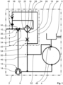
- FIG. 1 an embodiment of the washing machine according to the invention with the filter device according to the invention for carrying out the method according to the invention is shown purely as an example.
- the washing machine 2 designed as a household appliance comprises a tub 4, an emergency overflow 6 connected in a flow-conducting manner to an upper region of the tub 4, a wastewater pump 14 connected in a flow-conducting manner to the tub 4 by means of a pump inlet 8 and to a drain line 10 of the washing machine 2 by means of a pump outlet 12 Conveying wastewater (not shown) from the tub 4 into the drain line 10 and a filter device 16 for filtering the wastewater before it is introduced into the drain line 10.
- the filter device 16 comprises a filter 18 designed as a microparticle filter for removing microplastics (not shown) from the wastewater with a raw side 22 having a filter inlet 20 and a clean side 28 having at least one filter outlet 24, 26, the filter inlet 20 for the flow-conducting connection to the pump outlet 12 the wastewater pump 14 of the washing machine 2 and one of the at least one filter outlet 24 is designed for the flow-conducting connection to the drain line 10 of the washing machine 2 for discharging wastewater from the washing machine 2.
- a filter 18 designed as a microparticle filter for removing microplastics (not shown) from the wastewater with a raw side 22 having a filter inlet 20 and a clean side 28 having at least one filter outlet 24, 26, the filter inlet 20 for the flow-conducting connection to the pump outlet 12 the wastewater pump 14 of the washing machine 2 and one of the at least one filter outlet 24 is designed for the flow-conducting connection to the drain line 10 of the washing machine 2 for discharging wastewater from the washing machine 2.
- the filter device 16 is designed for installation in the washing machine 2, with a first filter output 24 of the clean side 28 of the filter 18 for the flow-conducting connection to the drain line 10 and a second filter output 26 of the clean side 28 of the filter 18 for the flow-conducting connection to the pump inlet 8 Wastewater pump 14 is formed.
- the filter device 16 has a valve 30 designed as a 3-way valve, the valve 30 having a valve inlet 32 which is connected to the pump outlet 12 in a flow-conducting manner, a first valve outlet 34 which can be connected in a flow-conducting manner to the valve inlet 32 for a flow-conducting connection to the filter inlet 20 and a second has a valve output 36 which can be connected to the valve inlet 32 in a flow-conducting manner for a direct flow-conducting connection to the drain line 10.
- the filter device 16 has a combined ventilation and ventilation 38 for the filter 18, the ventilation and ventilation 38 being connected in a flow-conducting manner to the first filter outlet 24, and the ventilation and ventilation 38 being simultaneously connected in a flow-conducting manner to the drain line 10 , namely such that the ventilation 38 by means of a Backflow preventer 40 is connected to the drain line 10 in a flow-conducting manner to prevent a backflow, not shown, from the drain line 10 to the clean side 28 of the filter 18.
- the filter device 16 also has a throttle 42 arranged in the flow direction after the second filter outlet 26, the throttle 42 in the flow-conducting connection of the filter 18 with the pump inlet 8 in the flow direction in front of one with the aforementioned flow-conducting connection and the combined Be - and ventilation 38 flow-conducting return line 44 is arranged for the return of gases, not shown, from the ventilation 38 into the tub 4 of the washing machine 2.
- the filter device 16 is designed here as a structural unit. See also the dash-dotted framing of the filter device 16 explained above in the Fig. 1 , which represents this circumstance.
- embodiments of the invention are also conceivable in which the filter device is not arranged as a structural unit, but rather, for example, distributed in an interior of the washing machine.
- Fig. 1 shows that the filter 18 is arranged in an upper area of the washing machine 2 at a height above the tub 4.
- the second filter outlet 26 of the filter 18 is here connected in a flow-conducting manner to the pump inlet 8 by means of a downpipe 46, the downpipe 46 being used to separate gas flowing to a tub inlet 48 of the tub 4 and wastewater flowing to the wastewater pump 14 by means of a downpipe outlet 50 of the Downpipe 46 in the direction of the tub inlet 48 rising connecting line 52 is connected in a flow-conducting manner to an upper region of the tub 4.
- the return line 44 is connected in a flow-conducting manner to the downcomer 46 by means of a downcomer connection 54 arranged in the flow direction between the throttle 42 and the downcomer outlet 50, with a clear diameter of the downcomer 46 being larger in the flow direction after the throttle 42 than in the flow direction in front of the throttle 42 is.
- the washing machine 2 is also designed in such a way that the filter 18 can be removed from the washing machine 2 on site, i.e. at the installation site of the washing machine 2 at the end customer.
- the valve 30 is automatically adjusted in such a way that the pump outlet 12 is connected in a flow-conducting manner to the filter inlet 20 by means of the valve inlet 32 and the first valve outlet 34 is.
- the liquor i.e. the wastewater
- the wastewater pump 14 flows from the tub 4 to the wastewater pump 14 by means of the pump inlet 8.
- the liquor reaches the raw side 22 of the filter 18 via the valve 30.
- the combined ventilation and ventilation 38 of the filter 18 ensures that the waste water pump 14 does not have to pump against a gas or foam cushion.
- the filtrate, not shown, i.e. the wastewater filtered by means of the filter 18, from the clean side 28 is largely passed into the drain line 10 via the backflow preventer 40.
- the appropriately designed ventilation 38 and the backflow preventer 40 ensure that, on the one hand, no filtrate from the filter 18 is conveyed through the ventilation 38 and, on the other hand, no filtrate is conveyed from the drain line 10 to the clean side 28 of the filter 18 can flow.
- the volume flow of the filtrate is divided via the throttle 42, with a defined smaller partial flow being returned to the suction side of the wastewater pump 14, i.e. to the pump inlet 8, while the larger partial flow is directed into the drain line 10 and thus into the wastewater installation, not shown.
- gases are returned from the ventilation 38 into the downpipe 46.
- the ventilation 38 is exchanged via the downpipe outlet 50 by means of the connecting line 52, the tub 4 and the emergency overflow 6 with the free environment .
- the height difference between the downpipe outlet 50 and the tub inlet 48 ensures a separation of gas and liquor, so that re-moistening of a load of the washing machine 2, i.e. laundry (not shown and treated by the washing machine 2), is prevented.
- the division of the volume flow of the liquor by means of the filter 18 generates a permanent volume flow via the filter 18 and the wastewater pump 14.
- the wastewater pump 14 conveys a portion of the wastewater in a circle and therefore does not enter into the so-called shuffling mode.
- the wastewater pump 14 can therefore react more quickly to increases in volume flow and the wastewater pump 14 and the entire wastewater system of the washing machine 2 do not have to be completely vented in advance, since the wastewater pump 14 already delivers. Due to the partial volume flow through the filter 18, it is continuously flushed with liquor during operation, so that biofilm formation is effectively reduced. This in turn reduces the sooting of the wastewater pump 14.
- the valve 30 is automatically adjusted in such a way that the pump outlet 12 is directly connected in a flow-conducting manner to the drain line 10 by means of the valve inlet 32 and the second valve outlet 36.
- the filter 18 is thus bypassed, the waste water pump 14 delivers directly into the drain line 10.
- the backflow preventer 40 prevents the filter 18 from being filled in an undesired manner from the clean side 28.
- the filter 18 is ventilated by means of the ventilation 38 and the liquor stored in the filter 18 can drain via the throttle 42 to the suction side of the wastewater pump 14, i.e. in the direction of the pump inlet 8, and is discharged by means of the wastewater pump 14 and the drain line 10 the washing machine 2 promoted.
- the fleet from the filter 18 is therefore not carried over into the following process step in the program flow of the automatic program.
- the drainage of the tub 4 of the washing machine 2 is stopped automatically.
- the wastewater system of the washing machine 2 is consistently separated from a water inlet, not shown, of the washing machine 2, so that, for example, an entry of germs or the like into the area of the water inlet of the washing machine 2 is effectively prevented.
- the permanent bypass flow via the wastewater pump 14 and the filter 18 during pumping, i.e. the drainage of the tub 4 of the washing machine 2, rinses the filter 18 with liquor and reduces, for example, biofilm formation. This effectively counteracts sooting of the waste water pump 14.
- the permanent bypass flow prevents a so-called slurping operation of the wastewater pump 14, which is comparable to the wastewater pump 14 running dry.
- the wastewater pump 14 always delivers liquid, i.e. wastewater, during pumping, so that, on the one hand, the risk of overheating of a motor (not shown) of the wastewater pump 14 and, on the other hand, the noise emissions of the wastewater pump 14 are significantly reduced.
- the ventilation 38 ensures that the wastewater pump 14 quickly reaches its delivery capacity.
- the bypass or leak volume flow is directed with the gas from the ventilation 38 in the downpipe 46 to the suction side of the wastewater pump 14.
- the downpipe outlet 50 to the tub 4 By means of the downpipe outlet 50 to the tub 4, the liquid phase and the gas phase are separated. This means that only the gas phase is returned to the tub 4. This reduces the risk of aerosol formation in a drum gap arranged in the tub 4 and in the Fig. 1 drum, not shown Load the washing machine 2 with laundry so that the spin result is improved.
- the filter 18 is emptied in a defined manner and the liquor carried over in the filter 18 can, after switching the valve 30 at the end of the drainage of the tub 4, be pumped out directly into the drain line 10 and thus into the house installation connected to it in a flow-conducting manner become.
- the filter 18 of the filter device 16 of the present exemplary embodiment is designed as a microparticle filter for removing microplastics or the like from the wastewater, it can be effectively prevented, for example when washing textiles made of synthetic fibers, that the smallest fibers are released during the washing process Textiles have loosened, with the waste water discharged from the washing machine 2 via the drain line 10 being released into the environment in an undesirable manner.
- Microplastics have become a very big problem for the environment these days, so the introduction of microplastics into the environment should be avoided as much as possible.
- the invention is not limited to the present exemplary embodiment. See, for example, the relevant statements in the introduction to the description.
Landscapes
- Engineering & Computer Science (AREA)
- Textile Engineering (AREA)
- Detail Structures Of Washing Machines And Dryers (AREA)
Applications Claiming Priority (1)
| Application Number | Priority Date | Filing Date | Title |
|---|---|---|---|
| BE20225734A BE1030879B1 (de) | 2022-09-15 | 2022-09-15 | Filtervorrichtung für eine Waschmaschine, Waschmaschine und Verfahren zum Betrieb einer Waschmaschine |
Publications (3)
| Publication Number | Publication Date |
|---|---|
| EP4339347A1 true EP4339347A1 (fr) | 2024-03-20 |
| EP4339347B1 EP4339347B1 (fr) | 2025-12-10 |
| EP4339347C0 EP4339347C0 (fr) | 2025-12-10 |
Family
ID=85157141
Family Applications (1)
| Application Number | Title | Priority Date | Filing Date |
|---|---|---|---|
| EP23192595.9A Active EP4339347B1 (fr) | 2022-09-15 | 2023-08-22 | Machine à laver et procédé de fonctionnement d'une machine à laver |
Country Status (4)
| Country | Link |
|---|---|
| EP (1) | EP4339347B1 (fr) |
| BE (1) | BE1030879B1 (fr) |
| ES (1) | ES3057821T3 (fr) |
| PL (1) | PL4339347T3 (fr) |
Citations (3)
| Publication number | Priority date | Publication date | Assignee | Title |
|---|---|---|---|---|
| WO2019045632A1 (fr) * | 2017-08-31 | 2019-03-07 | Roderinno Ab | Machine à laver et son procédé |
| WO2021197937A1 (fr) * | 2020-04-03 | 2021-10-07 | IFP Energies Nouvelles | Systeme et procede regenerable de filtration de microfibres d'un liquide de vidange |
| EP3907322A1 (fr) * | 2020-05-06 | 2021-11-10 | Vestel Beyaz Esya Sanayi Ve Ticaret A.S. | Dispositif de lavage comprenant un ensemble de filtration des microfibres |
-
2022
- 2022-09-15 BE BE20225734A patent/BE1030879B1/de active IP Right Grant
-
2023
- 2023-08-22 PL PL23192595.9T patent/PL4339347T3/pl unknown
- 2023-08-22 ES ES23192595T patent/ES3057821T3/es active Active
- 2023-08-22 EP EP23192595.9A patent/EP4339347B1/fr active Active
Patent Citations (3)
| Publication number | Priority date | Publication date | Assignee | Title |
|---|---|---|---|---|
| WO2019045632A1 (fr) * | 2017-08-31 | 2019-03-07 | Roderinno Ab | Machine à laver et son procédé |
| WO2021197937A1 (fr) * | 2020-04-03 | 2021-10-07 | IFP Energies Nouvelles | Systeme et procede regenerable de filtration de microfibres d'un liquide de vidange |
| EP3907322A1 (fr) * | 2020-05-06 | 2021-11-10 | Vestel Beyaz Esya Sanayi Ve Ticaret A.S. | Dispositif de lavage comprenant un ensemble de filtration des microfibres |
Also Published As
| Publication number | Publication date |
|---|---|
| ES3057821T3 (en) | 2026-03-04 |
| EP4339347B1 (fr) | 2025-12-10 |
| EP4339347C0 (fr) | 2025-12-10 |
| BE1030879A1 (de) | 2024-04-09 |
| PL4339347T3 (pl) | 2026-04-20 |
| BE1030879B1 (de) | 2024-04-15 |
Similar Documents
| Publication | Publication Date | Title |
|---|---|---|
| DE102019205919B4 (de) | Wasserführendes Haushaltsgerät und Verfahren zu seinem Betrieb | |
| DE69306672T2 (de) | Verfahren zum Reinigen von Wasser in einer Waschmaschine | |
| DE102020207163A1 (de) | Filtereinrichtung zur Filtration von Mikroplastik | |
| DE60133720T2 (de) | Aufbau der Flüssigkeitsdurchgänge in einer Spülmaschine | |
| DE19709085C2 (de) | Verfahren zum Waschen von Wäsche unter Verwendung eines Filtrationsverfahrens | |
| EP3663457B1 (fr) | Appareil électroménager conducteur d'eau et procédé de filtrage des fluides dans un appareil électroménager conducteur d'eau | |
| EP1078155B1 (fr) | Systeme d'alimentation en carburant pour vehicule | |
| EP4339347A1 (fr) | Dispositif de filtre pour machine à laver, machine à laver et procédé de fonctionnement d'une machine à laver | |
| DE102014224097B4 (de) | Ablauf- und Filtereinrichtung für eine Waschmaschine | |
| DE9208900U1 (de) | Anordnung zum Reinigen von Abwasser | |
| EP2627815B1 (fr) | Dispositif de nettoyage pour un élément exposé aux peluches, appareil ménager pour l'entretien du linge comprenant un tel dispositif de nettoyage ainsi que procédé pour nettoyer un élément exposé aux peluches | |
| EP3866663B1 (fr) | Lave-vaisselle ménager pourvu d'un système de filtre autonettoyant | |
| EP4259873B1 (fr) | Dispositif de filtrage pour un lave-vaisselle ou une machine à laver | |
| DE2827254B2 (de) | Waschmaschine mit einer elektrisch antreibbaren Laugenpumpe | |
| DE69301480T2 (de) | Kreiselpumpen | |
| DE102013222926A1 (de) | Wärmetauscheranordnung und Wäschetrockner | |
| DE102023116794A1 (de) | Vorrichtung für eine Waschmaschine und Waschmaschine | |
| DE202022106528U1 (de) | Filtereinrichtung zur Filtration von Mikroplastik aus Waschflüssigkeiten, und Waschmaschine hiermit | |
| EP4148176A1 (fr) | Aiguillage de liquide pour machine à laver, système de liquide, machine à laver et procédé de fonctionnement d'une machine à laver | |
| WO2010066539A1 (fr) | Appareil ménager pour l'entretien de pièces de linge, avec un tambour et un manchon | |
| DE102011087168A1 (de) | Haushaltsgerät und Steuerungsverfahren für ein Haushaltsgerät | |
| DE102016203179B3 (de) | Wäschepflegegerät mit einer Pumpe | |
| EP1615709A1 (fr) | Dispositif filtrant et procede pour le nettoyage periodique d'un filtre | |
| DE102024104064A1 (de) | Filtereinheit für ein Reinigungsgerät, Verfahren und Steuereinheit zum Betreiben der Filtereinheit und Reinigungsgerät | |
| DE102024104049A1 (de) | Waschmaschinen-Filtereinheit, Waschmaschine und Waschmaschinen-Satz |
Legal Events
| Date | Code | Title | Description |
|---|---|---|---|
| PUAI | Public reference made under article 153(3) epc to a published international application that has entered the european phase |
Free format text: ORIGINAL CODE: 0009012 |
|
| STAA | Information on the status of an ep patent application or granted ep patent |
Free format text: STATUS: THE APPLICATION HAS BEEN PUBLISHED |
|
| AK | Designated contracting states |
Kind code of ref document: A1 Designated state(s): AL AT BE BG CH CY CZ DE DK EE ES FI FR GB GR HR HU IE IS IT LI LT LU LV MC ME MK MT NL NO PL PT RO RS SE SI SK SM TR |
|
| STAA | Information on the status of an ep patent application or granted ep patent |
Free format text: STATUS: REQUEST FOR EXAMINATION WAS MADE |
|
| 17P | Request for examination filed |
Effective date: 20240920 |
|
| RBV | Designated contracting states (corrected) |
Designated state(s): AL AT BE BG CH CY CZ DE DK EE ES FI FR GB GR HR HU IE IS IT LI LT LU LV MC ME MK MT NL NO PL PT RO RS SE SI SK SM TR |
|
| GRAP | Despatch of communication of intention to grant a patent |
Free format text: ORIGINAL CODE: EPIDOSNIGR1 |
|
| STAA | Information on the status of an ep patent application or granted ep patent |
Free format text: STATUS: GRANT OF PATENT IS INTENDED |
|
| RIC1 | Information provided on ipc code assigned before grant |
Ipc: D06F 33/43 20200101AFI20250805BHEP Ipc: D06F 39/08 20060101ALI20250805BHEP Ipc: D06F 39/10 20060101ALI20250805BHEP Ipc: D06F 103/14 20200101ALN20250805BHEP Ipc: D06F 103/38 20200101ALN20250805BHEP Ipc: D06F 105/00 20200101ALN20250805BHEP Ipc: D06F 105/34 20200101ALN20250805BHEP Ipc: A47L 15/00 20060101ALN20250805BHEP |
|
| INTG | Intention to grant announced |
Effective date: 20250902 |
|
| GRAS | Grant fee paid |
Free format text: ORIGINAL CODE: EPIDOSNIGR3 |
|
| GRAA | (expected) grant |
Free format text: ORIGINAL CODE: 0009210 |
|
| STAA | Information on the status of an ep patent application or granted ep patent |
Free format text: STATUS: THE PATENT HAS BEEN GRANTED |
|
| AK | Designated contracting states |
Kind code of ref document: B1 Designated state(s): AL AT BE BG CH CY CZ DE DK EE ES FI FR GB GR HR HU IE IS IT LI LT LU LV MC ME MK MT NL NO PL PT RO RS SE SI SK SM TR |
|
| REG | Reference to a national code |
Ref country code: CH Ref legal event code: F10 Free format text: ST27 STATUS EVENT CODE: U-0-0-F10-F00 (AS PROVIDED BY THE NATIONAL OFFICE) Effective date: 20251210 Ref country code: GB Ref legal event code: FG4D Free format text: NOT ENGLISH |
|
| REG | Reference to a national code |
Ref country code: DE Ref legal event code: R096 Ref document number: 502023002421 Country of ref document: DE |
|
| REG | Reference to a national code |
Ref country code: IE Ref legal event code: FG4D Free format text: LANGUAGE OF EP DOCUMENT: GERMAN |
|
| U01 | Request for unitary effect filed |
Effective date: 20251210 |
|
| U07 | Unitary effect registered |
Designated state(s): AT BE BG DE DK EE FI FR IT LT LU LV MT NL PT RO SE SI Effective date: 20251216 |
|
| REG | Reference to a national code |
Ref country code: GB Ref legal event code: 746 Effective date: 20260203 |
|
| REG | Reference to a national code |
Ref country code: ES Ref legal event code: FG2A Ref document number: 3057821 Country of ref document: ES Kind code of ref document: T3 Effective date: 20260304 |
|
| REG | Reference to a national code |
Ref country code: ES Ref legal event code: GC2A Effective date: 20260303 |
|
| PG25 | Lapsed in a contracting state [announced via postgrant information from national office to epo] |
Ref country code: NO Free format text: LAPSE BECAUSE OF FAILURE TO SUBMIT A TRANSLATION OF THE DESCRIPTION OR TO PAY THE FEE WITHIN THE PRESCRIBED TIME-LIMIT Effective date: 20260310 |
|
| PG25 | Lapsed in a contracting state [announced via postgrant information from national office to epo] |
Ref country code: HR Free format text: LAPSE BECAUSE OF FAILURE TO SUBMIT A TRANSLATION OF THE DESCRIPTION OR TO PAY THE FEE WITHIN THE PRESCRIBED TIME-LIMIT Effective date: 20251210 |
|
| PG25 | Lapsed in a contracting state [announced via postgrant information from national office to epo] |
Ref country code: RS Free format text: LAPSE BECAUSE OF FAILURE TO SUBMIT A TRANSLATION OF THE DESCRIPTION OR TO PAY THE FEE WITHIN THE PRESCRIBED TIME-LIMIT Effective date: 20260310 |