EP4339351A1 - Ensemble d'alimentation en détergent de type filtre et appareil de lavage - Google Patents
Ensemble d'alimentation en détergent de type filtre et appareil de lavage Download PDFInfo
- Publication number
- EP4339351A1 EP4339351A1 EP22806406.9A EP22806406A EP4339351A1 EP 4339351 A1 EP4339351 A1 EP 4339351A1 EP 22806406 A EP22806406 A EP 22806406A EP 4339351 A1 EP4339351 A1 EP 4339351A1
- Authority
- EP
- European Patent Office
- Prior art keywords
- section
- water
- filtration
- filtering
- filtered
- Prior art date
- Legal status (The legal status is an assumption and is not a legal conclusion. Google has not performed a legal analysis and makes no representation as to the accuracy of the status listed.)
- Granted
Links
Images


Classifications
-
- D—TEXTILES; PAPER
- D06—TREATMENT OF TEXTILES OR THE LIKE; LAUNDERING; FLEXIBLE MATERIALS NOT OTHERWISE PROVIDED FOR
- D06F—LAUNDERING, DRYING, IRONING, PRESSING OR FOLDING TEXTILE ARTICLES
- D06F39/00—Details of washing machines not specific to a single type of machines covered by groups D06F9/00 - D06F27/00
- D06F39/02—Devices for adding soap or other washing agents
-
- D—TEXTILES; PAPER
- D06—TREATMENT OF TEXTILES OR THE LIKE; LAUNDERING; FLEXIBLE MATERIALS NOT OTHERWISE PROVIDED FOR
- D06F—LAUNDERING, DRYING, IRONING, PRESSING OR FOLDING TEXTILE ARTICLES
- D06F33/00—Control of operations performed in washing machines or washer-dryers
- D06F33/30—Control of washing machines characterised by the purpose or target of the control
- D06F33/43—Control of cleaning or disinfection of washing machine parts, e.g. of tubs
-
- D—TEXTILES; PAPER
- D06—TREATMENT OF TEXTILES OR THE LIKE; LAUNDERING; FLEXIBLE MATERIALS NOT OTHERWISE PROVIDED FOR
- D06F—LAUNDERING, DRYING, IRONING, PRESSING OR FOLDING TEXTILE ARTICLES
- D06F34/00—Details of control systems for washing machines, washer-dryers or laundry dryers
- D06F34/14—Arrangements for detecting or measuring specific parameters
-
- D—TEXTILES; PAPER
- D06—TREATMENT OF TEXTILES OR THE LIKE; LAUNDERING; FLEXIBLE MATERIALS NOT OTHERWISE PROVIDED FOR
- D06F—LAUNDERING, DRYING, IRONING, PRESSING OR FOLDING TEXTILE ARTICLES
- D06F34/00—Details of control systems for washing machines, washer-dryers or laundry dryers
- D06F34/14—Arrangements for detecting or measuring specific parameters
- D06F34/22—Condition of the washing liquid, e.g. turbidity
-
- D—TEXTILES; PAPER
- D06—TREATMENT OF TEXTILES OR THE LIKE; LAUNDERING; FLEXIBLE MATERIALS NOT OTHERWISE PROVIDED FOR
- D06F—LAUNDERING, DRYING, IRONING, PRESSING OR FOLDING TEXTILE ARTICLES
- D06F39/00—Details of washing machines not specific to a single type of machines covered by groups D06F9/00 - D06F27/00
- D06F39/08—Liquid supply or discharge arrangements
- D06F39/083—Liquid discharge or recirculation arrangements
-
- D—TEXTILES; PAPER
- D06—TREATMENT OF TEXTILES OR THE LIKE; LAUNDERING; FLEXIBLE MATERIALS NOT OTHERWISE PROVIDED FOR
- D06F—LAUNDERING, DRYING, IRONING, PRESSING OR FOLDING TEXTILE ARTICLES
- D06F39/00—Details of washing machines not specific to a single type of machines covered by groups D06F9/00 - D06F27/00
- D06F39/10—Filtering arrangements
-
- D—TEXTILES; PAPER
- D06—TREATMENT OF TEXTILES OR THE LIKE; LAUNDERING; FLEXIBLE MATERIALS NOT OTHERWISE PROVIDED FOR
- D06F—LAUNDERING, DRYING, IRONING, PRESSING OR FOLDING TEXTILE ARTICLES
- D06F2103/00—Parameters monitored or detected for the control of domestic laundry washing machines, washer-dryers or laundry dryers
- D06F2103/20—Washing liquid condition, e.g. turbidity
-
- D—TEXTILES; PAPER
- D06—TREATMENT OF TEXTILES OR THE LIKE; LAUNDERING; FLEXIBLE MATERIALS NOT OTHERWISE PROVIDED FOR
- D06F—LAUNDERING, DRYING, IRONING, PRESSING OR FOLDING TEXTILE ARTICLES
- D06F2103/00—Parameters monitored or detected for the control of domestic laundry washing machines, washer-dryers or laundry dryers
- D06F2103/42—Parameters monitored or detected for the control of domestic laundry washing machines, washer-dryers or laundry dryers related to filters or pumps
Definitions
- the present invention belongs to the field of home appliances, and specifically relates to a filtered detergent dispensing assembly and a washing apparatus.
- Microfibers are fiber particles less than 5mm in length.
- Browne et al. first suggested that home laundering of synthetic fiber garments is an important source of microfibers, and experimentally showed that a single washing of a garment can release more than 1,900 fibers, which drew attention to the source of microfibers released from home laundering.
- the IUCN International Union for the Conservation of Nature
- Chinese patent application No. CN201780096297.8 discloses a washing machine having a drum, a water collection tank below the drum, a water cycle, the water cycle comprising a withdrawable drawer for introducing detergents or additives, and the water cycle being fluidly connected to a detection device for detecting microfibers or contaminants in the water, as well as to a recirculation pump and to a tube for circulating the water.
- the method of operation comprises the steps of diverting a certain amount of water circulating in the circulation and delivering it to the detection device for analysis.
- activating a filtration process using a filtration device for filtering out microfibers from the water The microfibers that have been filtered out can be collected and the microfibers can then be easily removed from the washing machine.
- the filtration device in the above method can be used to filter microfibers and circulate the wash water, the filtration device is not capable of self-cleaning to remove debris accumulated in the filtration device.
- the technical problem to be solved by the present invention is to overcome the deficiencies of the prior art and to provide a filtered detergent dispensing assembly that is capable of filtering microfibers for filtering and circulating the washing water as well as cleaning the filtration module.
- the detergent dispensing assembly can not only realize holding detergent and adding detergent to the device to be added with detergent; it can also filter and circulate the washing water, integrating the detergent cassette and the filtration module, and reduce the occupied space of the filtration module; it can also realize cleaning the filtration module through the self-cleaning module, preventing the filtration module from being blocked and affecting the filtration effect.
- the filtering module comprises, a housing, provided in the drawer, forming a chamber inside;
- the first water inlet section and the first water outlet section are arranged on two opposite housing walls of the housing, respectively.
- the filtering section can filter the washing water entering the chamber through the first water inlet section, and the first valve body can control the opening and closing of the water path of the first water outlet section, and can choose whether to filter the washing water according to the need.
- the self-cleaning module comprises,
- the inlet end of the second inlet section and the inlet end of the first water inlet section are located on the same side of the housing.
- the inlet end of the second water outlet section and the outlet end of the first water inlet section are located on the same side of the housing.
- the self-cleaning module can flush the filtration module, and the direction of flushing is opposite to the direction of filtering debris, and the tap water ultimately enters the second outlet section from the side where the filtered water enters the filtration section to be discharged, so as to achieve the function of cleaning the filter module.
- the stowage section can collect the debris after cleaning, and therefore, as long as it is regularly cleaned in the stowage section to get rid of the debris.
- the inlet ends of the two water inlet sections is located at the same end of the housing, which can simplify the water inlet pipeline and facilitate water inlet; the inlet end of the second water outlet section and the outlet end of the first water inlet section are located at the same side of the housing, which simplifies the path of water passage.
- the self-cleaning module further comprises a scraping section, provided inside the housing, subjected to forceful movement for scraping debris from at least the filtration section.
- the scraping section scrapes the filter section, which prevents debris stuck inside the filter section from being easily flushed out, and thus improves the cleaning effect of the filter section.
- the filtering section is a hollow columnar structure with through holes in the outer wall, and the scraping section is provided in the inner cavity formed by the filtering section, in contact with the inner wall of the filtering section.
- an opening is provided at one end of the filtering section towards the first water inlet section for passing water to be filtered through the opening into the inner cavity.
- the scraping section is provided in a plurality.
- the scraping section is of a mesh plate-like structure, with each end movably resisting the inner wall of the filtering section.
- the hollow columnar structure with through holes on the outer wall can increase the area of the filtering section, and the water to be washed can be filtered from one end of the filtering section by completely passing into the inner cavity of the filtering section, thus ensuring the effect of filtration; since most of the debris accumulates in the inner cavity after filtration, setting a plurality of scraping sections in the inner cavity can improve the scraping efficiency.
- a gap is provided between at least one side of the peripheral wall of the filtration section and/or the end of the filtration section away from the first water inlet section and the inner wall of the housing, and the outlet end of the second water outlet section is provided in the gap.
- the outlet end of the second water outlet section is provided on a side close to the inlet side of the water to be filtered in the filtration section.
- the tap water can pass through the filtration section from a plurality of places outside the filtration section, and the filtration section is backwashed to ensure the cleaning effect; the outlet end of the second water outlet section is set on the side close to the inlet end of the water to be filtered in the filtration section to increase the flow path of the tap water, and then increase the contact rinsing area with the filtration section, and increase the rinsing and cleaning effect.
- the filtering section comprises,
- the filtration body is made of ultrafiltration and/or nanofiltration membranes and/or graphene material.
- the limit unit comprises,
- the limiting unit can prevent the filtration body from being deformed under the action of water pressure, resulting in the filter holes becoming larger, unable to filter the fine microfibers, and reducing the filtration effect, and can also play a filtering role, not hindering the filtration of sundries.
- the ultrafiltration membranes, nanofiltration membranes, graphene materials, and other materials have a microporous structure, which can filter microfibers and other small sundries, and achieve the effect of filtering and collecting microfibers.
- the fixed frame structure of the restriction unit makes the restriction unit, in addition to having the function of restricting the filtering body to prevent deformation, also play the role of fixing and connecting the shell and the filtering part, as well as installing the scraping part.
- the housing is also provided with a pressure detecting device, provided close to the filtration section, for detecting water pressure.
- the pressure detecting device can detect the water pressure close to the part of the filtering section, and when the water pressure is detected to be higher than a set value, it can be assumed that excessive debris has accumulated in the filtering section or that the pore structure on the filtering section has been clogged, and needs to be cleaned.
- Another object of the present invention is to provide a washing apparatus fitted with a filtered detergent dispensing assembly as described above.
- the washing apparatus comprises,
- the drainage assembly comprises,
- the present invention has the following beneficial effects compared with the prior art.
- connection In the description of the present invention, it is to be noted that, unless otherwise expressly specified and limited, the terms “connected”, “connected” are to be understood in a broad sense, e.g., either fixedly connected, detachably connected, or integrally connected; mechanically connected, or electrically connected; directly connected, or indirectly connected through an intermediary medium. It may be a mechanical connection or an electrical connection; it may be a direct connection or an indirect connection through an intermediate medium.
- the specific meaning of the above terms in the context of the present invention may be understood in specific cases.
- a filtered detergent dispensing assembly of the invention comprises a drawer 1 and a cassette 11 for holding the drawer 1, the drawer 1 comprises a detergent chamber 2 for holding detergent, a filtering module 3, disposed on the drawer 1 for filtering debris, and a self-cleaning module 4, in connection with the filtering module 3, for cleaning the filtering module 3.
- the detergent chamber 2 is provided at the end of the drawer 1 near the drawer fastener, and the filtration module 3 and self-cleaning module 4 are provided at the other end of the drawer 1.
- the cassette 11 is provided with a tap water inlet pipe and a valve for controlling the passage of water from the tap water inlet pipe to the drawer 1.
- the drawer 1 is provided with a water inlet connecting the tap water inlet pipe and the detergent chamber 2 for passing water into the detergent chamber 2 and for mixing the water with the detergent in the detergent chamber 2 and then discharging it from the outlet on the drawer 1.
- the detergent dispensing assembly of the present invention can realize both holding detergent and adding detergent to the device to be added; it can also integrate the detergent cassette with the filtration module 3 to realize filtering and circulating the washing water through the cassette assembly and reducing the occupied space of the filtration module 3; and it can also realize cleaning the filtration module 3 through the self-cleaning module 4, preventing the filtration module 3 from being clogged to affect the filtration effect.
- the filtration module 3 comprises a housing 31, provided in the drawer 1 and forming a chamber therein; a filtration section 32, provided in the housing 31 for filtering water to be filtered into the chamber; a first water inlet section 33, provided on the housing 31 for feeding water to be filtered into the chamber; a first outlet section 34, provided on the housing 31 with the inlet end of the first outlet section 34 on a different side from the outlet end of the first water inlet section 33 for discharging filtered water; a first valve body 35, provided on the first outlet section 34 for controlling the passage of water from the first outlet section 34sectionsectionsection.
- the first water inlet section 33 comprises a first water inlet connector running through the housing 31, preferably the first water inlet connector running through the wall on the side of the drawer 1 for connection with the device to be fitted with this detergent dispensing assembly, and water is input from the first water inlet connector into the housing 31.
- the first water outlet section 34 is an outlet running through the housing 31, the outlet being connected to the drawer 1, where the filtered water is discharged into the drawer 1 and discharged through an outlet on the drawer 1, where the outlet on the drawer 1 for discharging the detergent and the outlet on the drawer 1 for discharging the filtered water are one and the same outlet or different outlets, or where the first water outlet section 34 is a pipe running through the housing 31 and the drawer 1 at each end, where the filtered water is directly discharged through the pipe.
- the filtration section 32 is mounted on the inner wall of the housing 31, the first water inlet section 33 is located on one side of the filtration section 32, and the first water outlet section 34 is located on a different side of the filtration section 32 from the first water inlet section 33.
- the first water inlet section 33 and the first water outlet section 34 are disposed on two opposing shell walls of the housing 31, respectively.
- the filtering section 32 is detachably connected to the inner wall of the housing 31.
- the filtration section 32 of the present invention is capable of filtering the washing water entering the chamber through the first water inlet section 33, and the first valve body 35 is capable of controlling the opening and closing of the water path of the first water outlet section 34, and can choose whether to filter the washing water or not according to the need.
- the self-cleaning module 4 comprises, a second inlet section 43, provided on the housing 31 for passing tap water into the chamber from an orientation different from that of the water to be filtered through the filtration section 32; a second water outlet section 44, provided on the housing 31, with an inlet end located on a different side of the filtration section 32 from the outlet end of the second inlet section 43 and communicating with the outlet end of the first water inlet section 33 connected to the outlet end of the first water inlet section 33, for discharging tap water from the side of the filtration section 32 leading to the water to be filtered and leading to a stowage section 41; a stowage section 41, disposed downstream of the filtration section 32, for collecting debris carried on the discharged tap water removed from the filtration module 3; a second valve body 45, disposed on the second water outlet section 44, for controlling the passage of water in the water pathway of the second water outlet section 44.
- the stowage section 41 comprises a storage unit for filtering tap water discharged from the second water outlet section 44; a storage cavity, provided in the drawer 1, formed by a partition provided in the drawer 1 and an inner wall of the drawer 1 for holding the storage unit; and preferably, the storage unit is detachably provided in the storage cavity.
- the storage unit may be a mesh storage bag or storage box provided with micro perforations.
- the outlet end of the second water outlet section 44 is connected to the storage cavity, is located in the storage cavity or is articulated with an inlet of the storage cavity.
- the tap water passing through the stowage section 41 flows out of an outlet on the drawer 1, the outlet on the drawer 1 for discharging the tap water of the stowage section 41 being the same outlet as the outlet for discharging the detergent and/or the filtered water, or being a different outlet; or the tap water passing through the stowage section 41 flows out of a pipe running through the drawer 1.
- the outlet end of the stowage section 41 and/or outlet end of the first outlet section 34 is connected to the inlet of the detergent chamber 2, and the stowage section 41 and/or first outlet section 34 drains through the detergent chamber 2 to the outside of the drawer 1; alternatively, the outlet end of the stowage section 41, the outlet end of the first outlet section 34, and the inlet of the detergent chamber 2 are each independent.
- the inlet end of the second water inlet section 43 is located on the same side of the housing 31 as the inlet end of the first water inlet section 33, and preferably, the inlet end of the second water inlet section 43 and the inlet end of the first water inlet section 33 are provided in a shell wall on the side of the housing 31 away from the detergent chamber 2.
- the second water inlet section 43 comprises, a second water inlet connector 431, running through one side of the shell wall of the housing 31; an water inlet passage 432, connected to the outlet end of the second water inlet connector 431, with the outlet end of the water inlet passage 432 extending to the side of the filtration section 32 that avoids water to be washed being passed through into the filtration section 32, and, preferably, the second water inlet connector 431 running through the box wall of one side of the drawer 1 for connection to the equipment in which this detergent dispensing assembly is to be installed.
- the second water inlet connector 431 is provided close to the first water inlet section 33, and the water inlet passage 432 extends from the side of the first water inlet section 33 where it is connected with the second water inlet connector 431 to the side wall close to the side of the housing 31 provided with the second water inlet connector 431, and thereafter extends along the side wall to the side of the water to be filtered bypassing the filtering section 32.
- the first water inlet connector on the first water inlet section 33 runs through the water inlet passage 432 in a radial direction along the water inlet passage 432 located on the same side as the first water inlet section 33.
- the gap cooperates with the inner wall of the housing 31 and with the outer wall of the water inlet passage 432 on the side facing the first water inlet section 33 to form an inlet chamber for water to be filtered.
- the water inlet chamber of water to be filtered is communicated to one side of the filtering section 32 so that the water to be filtered passes completely through the filtering section 32 from one side of the filtering section 32.
- the water inlet passage 432 bypasses the side of the filtering section 32 through which the water to be filtered passes and input tap water to the filtering section 32 from the side of the housing 31 near the detergent chamber 2, and the water inlet chamber of the water to be filtered is communicated to the inlet end of the second water outlet section 44.
- the inlet end of the second water outlet section 44 is located on the same side wall of the housing 31 as the outlet end of the first water inlet section 33, away from the end of the outlet end of the first water inlet section 33, and the inlet end of the second inlet section 43 is located between the outlet end of the first water inlet section 33 and the inlet end of the second water outlet section 44.
- the inlet end of the filtration section 32 is connected to the inner wall of the housing 31 and to the outer wall of the water inlet passage 432.
- the outer wall of the water inlet passage 432 is connected to the side of the inlet end of the filtration section 32 facing the inlet end of the first water inlet section 33.
- a mesh mounting plate 311 is provided on the side wall of the housing 31 provided with the outlet end of the second water inlet section 43, with a gap between the mesh mounting plate 311 and the interior of the housing 31 on that side, with the outlet end of the second water inlet section 43 being connected to the gap.
- the edge of the inlet end of the filtration section 32 is connected to the mesh mounting plate 311 and the inner wall of the housing 31, respectively.
- the second water outlet section 44 comprises a second water outlet 441, provided on a shell wall of the housing 31 on the same side as the first water inlet section 33, in connection with the first water inlet section 33, the second valve body 45 being provided on the second water outlet 441; and an water outlet passage 442, provided against an outer wall of the housing 31 on the side opposite to the outlet end of the second water inlet section 43, extending to the stowage section 41, connecting the second water outlet 441 and the stowage section 41.
- the second water outlet 441 is communicated to the filtered water inlet chamber 36, the filtered water inlet chamber 36 forming a chamber for draining tap water after cleaning of the filtration module 3.
- the water inlet passage 432 and the water outlet passage 442 are formed by pipes provided on the housing 31 or by a sandwich of the housing 31 partially provided with a double shell wall.
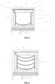
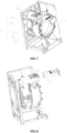
- the stowage section 41 is provided between the housing 31 and the detergent chamber 2, as shown in FIGS. 2 and 3 .
- the self-cleaning module 4 of the present invention can rinse the filtration module 3, and the rinsing direction is opposite to the direction of filtering debris, so as to achieve the function of cleaning the filtration module 3.
- the stowage section 41 can collect the debris after cleaning, so as long as it is regularly cleaned on the stowage section 41 to take off the debris; the inlet end of the two inlet sections is located on the same side of the housing 31, which can simplify the inlet water pipeline, and make it easy to enter the water.
- the self-cleaning module 4 further comprises a scraping section 42, provided inside the housing 31 and subjected to forceful movement for scraping debris from at least the filter section 32.
- the scraping section 42 is provided on the filtering section 32, the scraping section 42 is partially fixed to the filtering section 32, and is subjected to a forceful movement at least partially in contact with the filtering section 32 to scrape debris from the filtering section 32.
- the scraping section 42 is provided on the side of the filtration section 32 where the water to be filtered is passed through.
- the scraping section 42 of the present invention scrapes the filter section 32, which prevents debris stuck in the filter section 32 from being easily flushed out, which in turn improves the cleaning effect of the filter section 32.
- the filtering section 32 is a hollow cylindrical structure with through holes in the outer wall, and the scraping section 42 is provided in the inner cavity formed by the filtering section 32, in contact with the inner wall of the filtering section 32.
- the filtering section 32 is provided close to the inlet end of the first water inlet section 33.
- the scraping section 42 is provided on the inner wall of the filtering section 32 away from the end which the water to be filtered, and is fixedly connected to the filtering section 32.
- the scraping section 42 is a mesh plate structure, the middle part of the scraping section 42 is fixedly connected with the middle part of the inner wall of one end of the filtering section 32, and is set close to the inner wall of the filtering section 32, and the two ends of the scraping section 42 are respectively connected with the inner walls of the filtering section 32 on the two sides close to the side which is fixedly connected with the scraping section 42.
- the scraping section 42 has a deformable shape, and after being deformed by force, the two ends move relative to the filtering section 32 to scrape debris.
- the scraping section 42 may be fixedly connected to the filter section 32 by means of a connection 5 such as a screw.
- the shape of the scraping section 42 matches the shape of the inner peripheral wall of the filtering section 32, with the outer periphery of the scraping section 42 being movably pressed against the inner peripheral wall of the filtering section 32.
- the scraping sections 42 are provided in a plurality, spaced evenly along the central axis direction of the filtering section 32.
- the connecting member 5 is a connecting rod, one end of the connecting rod is fixedly connected to one end of the filtration section 32 away from the end of the water to be filtered, and the scraping sections 42 near the connecting rod at the end of the connecting end of the filtration section 32 are disposed close to the end wall of the filtration section 32.
- Each scraping section 42 passes through the connecting rod and is fixedly connected to the connecting rod. This embodiment can increase the contact area between the scraping section 42 and the filtering section 32, facilitate scraping of debris on the filtering section 32, and improve the cleaning efficiency of the filtering section 32.
- an opening is provided at one end of the filtering section 32 towards the first water inlet section 33 for passing water to be filtered through the opening into the inner chamber
- the side of the filtering section 32 in this embodiment which passes into the water to be filtered may also be infinitely close to the side provided with the first water inlet section 33, as shown in FIG. 5 .
- the hollow columnar structure of the filtration section 32 of the present invention with through holes on the outer wall can increase the area of contact with debris, and the water using in washing can be filtered from one side of the filtration section 32 into the inner cavity of the filtration section 32 completely, thus ensuring the effect of filtration. Since most of the debris accumulates in the inner cavity after filtration, setting a plurality of scraping sections 42 in the inner cavity improves the scraping efficiency.
- a gap is set between at least one side of the peripheral wall of the filtration section 32 and/or the end of the filtration section 32 away from the first water inlet section 33 and the inner wall of the housing 31, and the outlet end of the second water outlet section 44 is provided in the gap for passing tap water into the inner cavity for rinsing and cleaning of the filtration section 32.
- a gap is left between the peripheral wall of the filtration section 32 and the end of the filtration section 32 away from the first water inlet section 33 and the inner wall of the housing 31, forming an annular cavity, and the outlet end of the second water outlet section 44 is set on a side close to the side of the water to be filtered inlet side of the filtration section 32, so that water is flushed from the peripheral wall of the filtration section 32 and the end wall of one end of the filtration section 32 away from the first water inlet section 33 into the inner cavity through the annular cavity, and various parts of the filter section 32 are flushed and cleaned.
- the filtration section 32 comprises, a filtration body 321 for filtering debris, and a limiting unit 322, having a perforated structure, provided on the filtration body 321 for hindering the deformation of the filtration body 321 under force and limiting the change of the filter holes on the filtration body 321.
- the limiting unit 322 is provided against the filtration body 321.
- the filtration body 321 is made of materials such as ultrafiltration membranes and/or nanofiltration membranes and/or graphene, or the filtration body 321 is a filter mesh and/or filter plate structure with micropores, etc., which can be used for filtering microfibers and other tiny debris.
- the limiting unit 322 is provided on one side of the filtration body 321 or wrapped around the outer periphery of the filtration body 321, limiting the deformation of the filtration body 321 and preventing the filter holes on the filtration body 321 from becoming larger.
- the limiting unit 322 of the present invention prevents the filtration body 321 from being deformed by force under the action of water pressure, which results in the filter holes becoming larger, preventing filtration of fine microfibers and reducing the filtration effect.
- the limiting unit 322 comprises, a first fixing frame 3221, provided at one end of the filtration body 321 towards the first water inlet section 33, which can be fixedly connected to the inner wall of the housing 31 and the filter section 32; a second fixing frame 3222, provided at one end of the filtration body 321 away from the first fixing frame 3221, with the scraping section 42 being fixedly connected to the second fixing frame 3222; a third fixing frame 3223, provided on a peripheral wall of the filtering section 32.
- the first fixing frame 3221 is a plate-like structure having perforations covering or encompassing an end of the filtration body 321 facing the first water inlet section 33, a gap being left between an outer peripheral wall of the filtration body 321 and the inner wall of the housing 31 as well as the mesh mounting plate 311, and an outer peripheral end of the first fixing frame 3221 extending peripherally to the inner wall of the housing 31 and the mesh mounting plate 311, fixedly connected to the inner wall of the housing 31 and to the mesh mounting plate 311, the first fixing frame 3221 not having perforations on the extended section of the first fixing frame 3221.
- the outer wall of the outlet end of the second inlet section 43 is sealingly connected to the side of the extension section facing the inlet end of the first water inlet section 33, and the outlet end of the second inlet section 43 is located on the outer side of the peripheral wall of the filtration section 32.
- the filtration body 321 is provided with an opening at the end of the filtration body 321 that passes through the water to be filtered, then the first fixing frame 3221 may also be located at the periphery of the opening to form the extension that does not have a perforation.
- the second fixing frame 3222 is a plate-like structure having perforations covering or encompassing one end of the filtering body 321 opposite the first fixing frame 3221, and the connecting member 5 penetrates through both sides of the second fixing frame 3222 and filtering body 321 to be fixedly connected to filtering section 32.
- the third fixing frame 3223 is of coil spring construction, socketed to the inner and outer circumferential walls of the filtration body 321.
- the limiting unit 322 of the present invention in addition to having the function of limiting the filtering body against deformation, also serves to securely connect the housing 31 and the filtering section 32, as well as to mount the scraping section 42.
- the housing 31 is further provided with a pressure detecting device 6, provided close to the filtering section 32, for detecting the water pressure.
- the pressure detecting device 6 is provided on the filtration section 32 and/or on the inner wall of the housing 31 and/or on the second water inlet section 43.
- the pressure detecting device 6 of the present invention detects the water pressure close to the part of the filtering section 32, and when the water pressure is detected to be higher than a set value, it can be assumed that excessive debris has accumulated in the filtering section 32 and needs to be cleaned.
- the pressure detection device 6 detects that the pressure is greater than a set value, it is considered that a large amount of debris is attached to the filtration section 32 or that it has been clogged, and the filtration module 3 needs to be cleaned.
- the first valve body 35 is closed and the second valve body 45 is opened, and tap water is passed from the second water inlet section 43 into the annular cavity, and the water flow enters the inner cavity of the filtration section 32 through the annular cavity from the periphery of the filtration section 32 and the exterior of one end away from the filtered water inlet chamber 36, under the action of water pressure, the scraping section 42 is deformed by the force, and both ends of the movement along the direction of the water flow to scrape the sundries on the inner wall of the filtering section 32, and the tap water with sundries is ultimately discharged from the second water outlet section 44 connected to the filtered water inlet chamber to reverse rinse the filtering section 32, and the rinsed tap water is discharged into the stowage section 41, and is finally discharged out of the drawer 1 being filtered by the filtering section 41.
- a washing apparatus of the present invention having a filtered detergent dispensing assembly as described above, comprising an outer drum 7; a drainage assembly 8, connected to the outer drum 7 for draining water in the outer cassette 7 to the outside of the machine or into the filtered detergent dispensing assembly; an inlet pipe 10, connected to the cassette 11 and the outer drum 7 for passing liquid from the detergent dispensing assembly into the outer drum 7; a judgment module for determining whether the filtration module 3 is clogged or not at least on the basis of the detected water pressure; a control module for controlling the state of the drainage assembly 8 and the operating state of the filtration module 3 and self-cleaning module 4 at least on the basis of the washing program and the clogged condition of the filtration module 3 as determined by the judgment module.
- the drainage assembly 8 comprises, a first drain pipe 81, connected to the outer drum 7 for draining water from the outer drum 7; a three-way valve 84, the inlet end of which is connected to the first drain pipe 81; a second drain pipe 82, connected to one outlet end of the three-way valve 84 for draining water from the first drain pipe 81 out of the machine body; a circulation water pipe 83, the inlet end of which is connected to the other outlet end of the three-way valve 84 and the outlet end removably connected with the first water inlet section 33, for passing the water in the first drain pipe 81 into the detergent dispensing assembly for filtering and circulating.
- the control module may control the opening and closing state of the three-way valve 84 as well as the working state of the filtration module 3 and the self-cleaning module 4 according to the washing program and the clogging state of the filtration module as judged by the judgment module.
- the cassette 11 is fixedly mounted on the outer wall of the outer drum 7, and the outlet end of the circulating water pipe 83 is provided on the cassette 11, matching the position of the inlet end of the first inlet section 33, and matched with the first inlet connector of the first inlet section 33 for removable connection.
- the washing apparatus further comprises a tap water inlet hose, connected to the cassette 11, removably connected to a second inlet connector 431 of the second inlet section 43.
- the tap water inlet hose comprises, a first inlet hose, removable connected to the second inlet connector 431 of the second inlet section 43; and a second inlet hose, removable connected to the inlet of the detergent chamber 2.
- the first drain pipe 81, second drain pipe 82, recirculation water pipe 83, and three-way valve 84 are provided on the same side of the washing apparatus, near the rear part of the washing apparatus.
- the first drain pipe 81 is provided with a drainage pump 85.
- the first drain pipe 81 is also provided with a detection device for detecting the content of microfibers and/or debris in the washing water in the first drain pipe 81.
- the control module controls the three-way valve 84 to open the valve leading to the second drain pipe 82, and directly discharges the washing water out of the machine body.
- the judgment module to the pressure detected by the pressure detection device 6 is greater than a set value, the judgment result is sent to the control module, and the control module controls the opening of the tap water inlet pipe to pass water into the second water inlet section 43 to clean the filtration module 3.
- the washing apparatus of the present invention can choose to control the water discharged from the outer drum 7 to be filtered through the detergent delivery assembly and then passed into the outer drum 7 according to the actual situation, so as to achieve the function of circulating the washing water as well as preventing the microfibers from eventually entering into the soil and causing harm to the environment; or choose to discharge directly, so as to make full use of the function of the detergent assembly's water intake, and to reduce the space occupied by the filtration module 3 and the self-cleaning module 4.
Landscapes
- Engineering & Computer Science (AREA)
- Textile Engineering (AREA)
- Separation Using Semi-Permeable Membranes (AREA)
- Detail Structures Of Washing Machines And Dryers (AREA)
- Cleaning By Liquid Or Steam (AREA)
Applications Claiming Priority (2)
| Application Number | Priority Date | Filing Date | Title |
|---|---|---|---|
| CN202110505294.3A CN115323723B (zh) | 2021-05-10 | 2021-05-10 | 一种过滤式洗涤剂投放组件及洗涤设备 |
| PCT/CN2022/086493 WO2022237436A1 (fr) | 2021-05-10 | 2022-04-13 | Ensemble d'alimentation en détergent de type filtre et appareil de lavage |
Publications (3)
| Publication Number | Publication Date |
|---|---|
| EP4339351A1 true EP4339351A1 (fr) | 2024-03-20 |
| EP4339351A4 EP4339351A4 (fr) | 2024-10-23 |
| EP4339351B1 EP4339351B1 (fr) | 2026-08-19 |
Family
ID=83912156
Family Applications (1)
| Application Number | Title | Priority Date | Filing Date |
|---|---|---|---|
| EP22806406.9A Active EP4339351B1 (fr) | 2021-05-10 | 2022-04-13 | Ensemble d'alimentation en détergent de type filtre et appareil de lavage |
Country Status (4)
| Country | Link |
|---|---|
| US (1) | US20240271352A1 (fr) |
| EP (1) | EP4339351B1 (fr) |
| CN (1) | CN115323723B (fr) |
| WO (1) | WO2022237436A1 (fr) |
Families Citing this family (3)
| Publication number | Priority date | Publication date | Assignee | Title |
|---|---|---|---|---|
| US12546053B2 (en) * | 2021-05-10 | 2026-02-10 | Qingdao Haier Drum Washing Machine Co., Ltd. | Liquid storage box, additive dispensing apparatus and identification method |
| EP4506501A4 (fr) * | 2022-06-28 | 2025-07-09 | Samsung Electronics Co Ltd | Machine à laver et procédé de commande de machine à laver |
| US12630963B2 (en) | 2023-08-28 | 2026-05-19 | Whirlpool Corporation | Fluid treatment module for an appliance that includes a microfiber filter access mechanism |
Family Cites Families (16)
| Publication number | Priority date | Publication date | Assignee | Title |
|---|---|---|---|---|
| US2663429A (en) * | 1950-02-28 | 1953-12-22 | Le Roy T Bossard | Liquid or gas self-cleaning filter and strainer |
| US3896641A (en) * | 1973-07-30 | 1975-07-29 | Gen Electric | Combination lint filter and additive dispenser for automatic washer |
| JPH0615092A (ja) * | 1992-07-03 | 1994-01-25 | Nippon Kentetsu Co Ltd | 洗濯機の洗剤供給装置 |
| KR20060031164A (ko) * | 2004-10-07 | 2006-04-12 | 엘지전자 주식회사 | 건조 세탁기 |
| TW201300159A (zh) * | 2011-06-28 | 2013-01-01 | Arcadia Filter Ltd | 無動力自動刮洗濾心 |
| CN102767067A (zh) * | 2012-08-13 | 2012-11-07 | 王国全 | 一种无排水的循环滤水洗衣机及其洗衣方法 |
| CN104947387B (zh) * | 2014-03-27 | 2019-06-28 | 青岛海尔洗衣机有限公司 | 一种具有自清洁功能的洗衣机循环节水过滤装置及洗衣机 |
| CN204185692U (zh) * | 2014-09-22 | 2015-03-04 | 合肥市宏键精工模具有限责任公司 | 一种自动清洁净水洗装置 |
| CN104499244B (zh) * | 2014-12-10 | 2023-05-16 | 合肥市宏键精工模具有限责任公司 | 一种滚筒洗衣机用进水盒组件 |
| JP6936593B2 (ja) * | 2017-03-06 | 2021-09-15 | 東芝ライフスタイル株式会社 | 洗濯機 |
| JP6952489B2 (ja) * | 2017-04-20 | 2021-10-20 | 日立グローバルライフソリューションズ株式会社 | フィルタ清掃機構およびそれを用いた布類乾燥装置 |
| KR102528052B1 (ko) * | 2017-10-25 | 2023-05-02 | 에.게.오. 에렉트로-게래테바우 게엠베하 | 세탁기의 작동 방법 및 세탁기 |
| CN109957924B (zh) * | 2017-12-25 | 2022-09-23 | 佛山海尔滚筒洗衣机有限公司 | 一种污水过滤回收装置、洗衣机及控制方法 |
| DE102019201804A1 (de) * | 2019-02-12 | 2020-08-13 | BSH Hausgeräte GmbH | Haushaltsgerät mit einem Filterelement |
| TR201913423A2 (fr) * | 2019-09-05 | 2021-03-22 | Arcelik As | |
| CN112376245B (zh) * | 2020-09-30 | 2022-05-31 | 无锡小天鹅电器有限公司 | 过滤器组件和衣物处理设备 |
-
2021
- 2021-05-10 CN CN202110505294.3A patent/CN115323723B/zh active Active
-
2022
- 2022-04-13 US US18/560,198 patent/US20240271352A1/en active Pending
- 2022-04-13 EP EP22806406.9A patent/EP4339351B1/fr active Active
- 2022-04-13 WO PCT/CN2022/086493 patent/WO2022237436A1/fr not_active Ceased
Also Published As
| Publication number | Publication date |
|---|---|
| WO2022237436A1 (fr) | 2022-11-17 |
| US20240271352A1 (en) | 2024-08-15 |
| EP4339351A4 (fr) | 2024-10-23 |
| CN115323723A (zh) | 2022-11-11 |
| EP4339351B1 (fr) | 2026-08-19 |
| CN115323723B (zh) | 2026-06-16 |
Similar Documents
| Publication | Publication Date | Title |
|---|---|---|
| US20240271352A1 (en) | Filtered detergent dispensing assembly and washing apparatus | |
| CA2345190C (fr) | Filtre auto-nettoyant avec derivation | |
| JP7823818B2 (ja) | 濾過装置及び洗濯機 | |
| CN111676669B (zh) | 一种洗涤设备及控制方法 | |
| KR101332286B1 (ko) | 세탁기 | |
| CN102471981A (zh) | 具有位于泵出区段中的过滤装置和储存箱的带水运行的家用器具 | |
| JP2025525846A (ja) | 濾過モジュール、濾過モジュールの制御方法及び洗浄機器 | |
| JP2000024385A (ja) | 洗濯機 | |
| CN117661248A (zh) | 一种洗涤设备的控制方法及洗涤设备 | |
| CN219218465U (zh) | 一种过滤模块及洗涤设备 | |
| WO2022042271A1 (fr) | Machine à laver et son procédé de commande | |
| WO2014089651A1 (fr) | Dispositif pour retenir de façon unidirectionnelle des solides prévu pour des fluides, système de lignes d'écoulement pour machines à laver, et procédé dans un système de lignes d'écoulement d'une machine à laver | |
| CN105518204A (zh) | 具有旁通阀的家用器具 | |
| JP2025536067A (ja) | 濾過システム、濾過モジュール、洗濯設備及び制御方法 | |
| JPH11276794A (ja) | 洗濯機 | |
| CN219815858U (zh) | 一种罐式超滤装置 | |
| CN218492047U (zh) | 一种过滤模块及洗涤设备 | |
| CN112726143B (zh) | 排水阀及衣物处理装置 | |
| WO2024230002A1 (fr) | Système de filtration de dispositif de lavage, et dispositif de lavage | |
| CN110644200A (zh) | 具有自清洁功能的洗涤设备 | |
| WO2018210313A1 (fr) | Appareil de filtrage de peluches et lave-linge | |
| CN210596692U (zh) | 毛绒收集装置及其洗衣机 | |
| CN223907188U (zh) | 一种循环过滤装置及衣物处理设备 | |
| JP2013202154A (ja) | 洗濯機 | |
| CN219308092U (zh) | 一种烛芯式过滤器全自动清洗系统 |
Legal Events
| Date | Code | Title | Description |
|---|---|---|---|
| STAA | Information on the status of an ep patent application or granted ep patent |
Free format text: STATUS: THE INTERNATIONAL PUBLICATION HAS BEEN MADE |
|
| PUAI | Public reference made under article 153(3) epc to a published international application that has entered the european phase |
Free format text: ORIGINAL CODE: 0009012 |
|
| STAA | Information on the status of an ep patent application or granted ep patent |
Free format text: STATUS: REQUEST FOR EXAMINATION WAS MADE |
|
| 17P | Request for examination filed |
Effective date: 20231204 |
|
| AK | Designated contracting states |
Kind code of ref document: A1 Designated state(s): AL AT BE BG CH CY CZ DE DK EE ES FI FR GB GR HR HU IE IS IT LI LT LU LV MC MK MT NL NO PL PT RO RS SE SI SK SM TR |
|
| DAV | Request for validation of the european patent (deleted) | ||
| DAX | Request for extension of the european patent (deleted) | ||
| A4 | Supplementary search report drawn up and despatched |
Effective date: 20240925 |
|
| RIC1 | Information provided on ipc code assigned before grant |
Ipc: D06F 103/42 20200101ALN20240919BHEP Ipc: D06F 103/20 20200101ALN20240919BHEP Ipc: D06F 39/08 20060101ALN20240919BHEP Ipc: D06F 33/43 20200101ALN20240919BHEP Ipc: D06F 39/10 20060101ALI20240919BHEP Ipc: D06F 39/02 20060101AFI20240919BHEP |
|
| RIC1 | Information provided on ipc code assigned before grant |
Ipc: D06F 39/02 20060101AFI20260304BHEP Ipc: D06F 39/10 20060101ALI20260304BHEP Ipc: D06F 33/43 20200101ALN20260304BHEP Ipc: D06F 39/08 20060101ALN20260304BHEP Ipc: D06F 103/20 20200101ALN20260304BHEP Ipc: D06F 103/42 20200101ALN20260304BHEP |
|
| RIC1 | Information provided on ipc code assigned before grant |
Ipc: D06F 39/02 20060101AFI20260317BHEP Ipc: D06F 39/10 20060101ALI20260317BHEP Ipc: D06F 33/43 20200101ALN20260317BHEP Ipc: D06F 39/08 20060101ALN20260317BHEP Ipc: D06F 103/20 20200101ALN20260317BHEP Ipc: D06F 103/42 20200101ALN20260317BHEP |
|
| GRAP | Despatch of communication of intention to grant a patent |
Free format text: ORIGINAL CODE: EPIDOSNIGR1 |
|
| STAA | Information on the status of an ep patent application or granted ep patent |
Free format text: STATUS: GRANT OF PATENT IS INTENDED |
|
| RIC1 | Information provided on ipc code assigned before grant |
Ipc: D06F 39/02 20060101AFI20260414BHEP Ipc: D06F 39/10 20060101ALI20260414BHEP Ipc: D06F 33/43 20200101ALN20260414BHEP Ipc: D06F 39/08 20060101ALN20260414BHEP Ipc: D06F 103/20 20200101ALN20260414BHEP Ipc: D06F 103/42 20200101ALN20260414BHEP |
|
| RIC1 | Information provided on ipc code assigned before grant |
Ipc: D06F 39/02 20060101AFI20260421BHEP Ipc: D06F 39/10 20060101ALI20260421BHEP Ipc: D06F 33/43 20200101ALN20260421BHEP Ipc: D06F 39/08 20060101ALN20260421BHEP Ipc: D06F 103/20 20200101ALN20260421BHEP Ipc: D06F 103/42 20200101ALN20260421BHEP |
|
| INTG | Intention to grant announced |
Effective date: 20260508 |
|
| GRAS | Grant fee paid |
Free format text: ORIGINAL CODE: EPIDOSNIGR3 |
|
| GRAA | (expected) grant |
Free format text: ORIGINAL CODE: 0009210 |
|
| STAA | Information on the status of an ep patent application or granted ep patent |
Free format text: STATUS: THE PATENT HAS BEEN GRANTED |