EP4339364A2 - Procédé de fabrication d'un récipient contenant des fibres et dispositif - Google Patents
Procédé de fabrication d'un récipient contenant des fibres et dispositif Download PDFInfo
- Publication number
- EP4339364A2 EP4339364A2 EP23175928.3A EP23175928A EP4339364A2 EP 4339364 A2 EP4339364 A2 EP 4339364A2 EP 23175928 A EP23175928 A EP 23175928A EP 4339364 A2 EP4339364 A2 EP 4339364A2
- Authority
- EP
- European Patent Office
- Prior art keywords
- container
- application head
- controlled application
- fibers
- coating
- Prior art date
- Legal status (The legal status is an assumption and is not a legal conclusion. Google has not performed a legal analysis and makes no representation as to the accuracy of the status listed.)
- Withdrawn
Links
Images


Classifications
-
- D—TEXTILES; PAPER
- D21—PAPER-MAKING; PRODUCTION OF CELLULOSE
- D21J—FIBREBOARD; MANUFACTURE OF ARTICLES FROM CELLULOSIC FIBROUS SUSPENSIONS OR FROM PAPIER-MACHE
- D21J7/00—Manufacture of hollow articles from fibre suspensions or papier-mâché by deposition of fibres in or on a wire-net mould
-
- B—PERFORMING OPERATIONS; TRANSPORTING
- B29—WORKING OF PLASTICS; WORKING OF SUBSTANCES IN A PLASTIC STATE IN GENERAL
- B29C—SHAPING OR JOINING OF PLASTICS; SHAPING OF MATERIAL IN A PLASTIC STATE, NOT OTHERWISE PROVIDED FOR; AFTER-TREATMENT OF THE SHAPED PRODUCTS, e.g. REPAIRING
- B29C64/00—Additive manufacturing, i.e. manufacturing of three-dimensional [3D] objects by additive deposition, additive agglomeration or additive layering, e.g. by 3D printing, stereolithography or selective laser sintering
- B29C64/10—Processes of additive manufacturing
- B29C64/171—Processes of additive manufacturing specially adapted for manufacturing multiple 3D objects
- B29C64/182—Processes of additive manufacturing specially adapted for manufacturing multiple 3D objects in parallel batches
-
- B—PERFORMING OPERATIONS; TRANSPORTING
- B29—WORKING OF PLASTICS; WORKING OF SUBSTANCES IN A PLASTIC STATE IN GENERAL
- B29D—PRODUCING PARTICULAR ARTICLES FROM PLASTICS OR FROM SUBSTANCES IN A PLASTIC STATE
- B29D22/00—Producing hollow articles
- B29D22/003—Containers for packaging, storing or transporting, e.g. bottles, jars, cans, barrels, tanks
-
- B—PERFORMING OPERATIONS; TRANSPORTING
- B33—ADDITIVE MANUFACTURING TECHNOLOGY
- B33Y—ADDITIVE MANUFACTURING, i.e. MANUFACTURING OF THREE-DIMENSIONAL [3D] OBJECTS BY ADDITIVE DEPOSITION, ADDITIVE AGGLOMERATION OR ADDITIVE LAYERING, e.g. BY 3D PRINTING, STEREOLITHOGRAPHY OR SELECTIVE LASER SINTERING
- B33Y70/00—Materials specially adapted for additive manufacturing
- B33Y70/10—Composites of different types of material, e.g. mixtures of ceramics and polymers or mixtures of metals and biomaterials
-
- B—PERFORMING OPERATIONS; TRANSPORTING
- B33—ADDITIVE MANUFACTURING TECHNOLOGY
- B33Y—ADDITIVE MANUFACTURING, i.e. MANUFACTURING OF THREE-DIMENSIONAL [3D] OBJECTS BY ADDITIVE DEPOSITION, ADDITIVE AGGLOMERATION OR ADDITIVE LAYERING, e.g. BY 3D PRINTING, STEREOLITHOGRAPHY OR SELECTIVE LASER SINTERING
- B33Y80/00—Products made by additive manufacturing
-
- D—TEXTILES; PAPER
- D21—PAPER-MAKING; PRODUCTION OF CELLULOSE
- D21J—FIBREBOARD; MANUFACTURE OF ARTICLES FROM CELLULOSIC FIBROUS SUSPENSIONS OR FROM PAPIER-MACHE
- D21J3/00—Manufacture of articles by pressing wet fibre pulp, or papier-mâché, between moulds
-
- D—TEXTILES; PAPER
- D21—PAPER-MAKING; PRODUCTION OF CELLULOSE
- D21J—FIBREBOARD; MANUFACTURE OF ARTICLES FROM CELLULOSIC FIBROUS SUSPENSIONS OR FROM PAPIER-MACHE
- D21J3/00—Manufacture of articles by pressing wet fibre pulp, or papier-mâché, between moulds
- D21J3/10—Manufacture of articles by pressing wet fibre pulp, or papier-mâché, between moulds of hollow bodies
-
- B—PERFORMING OPERATIONS; TRANSPORTING
- B33—ADDITIVE MANUFACTURING TECHNOLOGY
- B33Y—ADDITIVE MANUFACTURING, i.e. MANUFACTURING OF THREE-DIMENSIONAL [3D] OBJECTS BY ADDITIVE DEPOSITION, ADDITIVE AGGLOMERATION OR ADDITIVE LAYERING, e.g. BY 3D PRINTING, STEREOLITHOGRAPHY OR SELECTIVE LASER SINTERING
- B33Y10/00—Processes of additive manufacturing
-
- B—PERFORMING OPERATIONS; TRANSPORTING
- B33—ADDITIVE MANUFACTURING TECHNOLOGY
- B33Y—ADDITIVE MANUFACTURING, i.e. MANUFACTURING OF THREE-DIMENSIONAL [3D] OBJECTS BY ADDITIVE DEPOSITION, ADDITIVE AGGLOMERATION OR ADDITIVE LAYERING, e.g. BY 3D PRINTING, STEREOLITHOGRAPHY OR SELECTIVE LASER SINTERING
- B33Y30/00—Apparatus for additive manufacturing; Details thereof or accessories therefor
Definitions
- the invention relates to a method for producing a container and a device, for example for carrying out the method, according to the independent claims.
- the object of the invention is to provide a method for producing a container comprising fibers and a device, for example for carrying out the method, which enable the production of a container which has sufficient tightness, barrier effect and strength.
- the method according to the invention is for producing a container comprising fibers by means of a controlled application head which applies material comprising the fibers to container positions.
- the fibers for example paper fibers
- the fibers can be applied dry or wet or as pulp to the container positions where material is to be located in the manufactured container.
- adhesive and/or connection points can be avoided between container parts that were produced, for example, using different manufacturing processes, which may include different times and/or different types of processes.
- adhesive and/or connection points between container parts problems that can relate to tightness, barrier effect and/or moisture can be avoided.
- the container can be largely completed using the application head, filled with a product and then closed using the same or a different application head.
- a previously produced closure can be applied to the container, for example by screwing it on.
- It can also include producing an open-topped container using a mold and closing the container using the application head.
- the material can be applied to an inner wall of a mold by means of the controlled application head and the container can be produced by pressing or molding using a balloon in the mold.
- the material can be applied using a 3D printer, for example a layered structure can be provided for the application.
- a 3D printer the water content of the material comprising the fibers can, for example, be chosen to be smaller than when the material is applied to an inner wall of a mold using the controlled application head.
- the drying phase of the container produced can be shorter.
- a large number of containers can be produced at the same time. For example, all of the plurality of nozzles can be moved by a common drive.
- the controlled application head can be moved using a multi-axis robot.
- the multi-axis robot may include a 3-, 4-, 5-, 6- or 7-axis robot, for example a 3-, 4-, 5-, 6- or 7-axis articulated robot.
- the material can be applied to a container that has already been at least partially manufactured in order to further produce a partial element of the container and at the same time connect the partial element to the already at least partially manufactured container.
- the sub-element can comprise a mouthpiece and/or a handle and/or a thread.
- the thread can be pressed after the thread has been produced.
- At least one further, fiber-containing material can be applied to container positions, wherein the at least one further, fiber-containing material can be different from the material that comprises the fibers.
- a further, fiber-containing material can be used for a thread or a thread area, which, after the container has been manufactured, creates a thread or a thread area that has greater stability than the rest of the container.
- identification information and/or shelf life information can be embossed on the container.
- a pressing tool can be arranged on the application head or separately, with which the mass that has just been applied can be pressed or compressed step by step after application.
- the pressing tool can, for example, comprise two opposing plates, each of which can be smaller than 5 cm 2 , for example smaller than 1 cm 2 , and can press the applied material together.
- the pressing tool can, for example, be arranged at least partially around the application head.
- a drying device for drying the material can be arranged on the device.
- the drying device can include a fan.
- the drying device and/or the pressing tool can be arranged on the application head or can be moved along the contour of the container using their own drives.
- At least one support can be provided within the container, which can, for example, connect two or more interior areas of the container.
- a container may be an independent invention.
- the container can, for example, have thinner wall thicknesses than a corresponding container without the at least one support.
- the at least one support is surrounded by the material when producing the container by means of the controlled applicator head, which applies material comprising the fibers to container positions.
- the at least one support can be embedded in the material comprising the fibers.
- a floor area and a shoulder area or a floor area and a side part area can be connected by means of the at least one support.
- the container can, for example, have a thinner bottom thickness than a corresponding container without the at least one support.
- the at least one support can be arranged obliquely.
- the at least one support can connect a side part area and a shoulder area all around.
- the at least one support can be designed to run horizontally be. It can serve to ensure that the container can withstand pressure when filled with a product containing carbon dioxide. It can also or alternatively serve to provide additional stability when dynamic pressure acts on the container during transport on a conveyor.
- the at least one support can connect a side part area and a bottom area all around.
- the at least one support can be designed to run horizontally. It can serve to ensure that the container can withstand pressure when filled with a product containing carbon dioxide.
- the supports can include a drawstring for a bottom of the container and/or at least one horizontally circumferential drawstring and/or at least one oblique drawstring.
- these drawstrings can comprise long-fiber material.
- An oblique tension band that connects the base and a side part area prevents the base from bulging outwards when, for example, product containing carbon dioxide is poured into the container produced.
- a center of the floor area and a shoulder area or a center of the floor area and a side part area can be connected by means of the at least one support.
- the support can act as a tension band, which counteracts expansion of the bottom area, or the center of the bottom area, away from the center (usually downwards towards the center of the earth when the container is standing on the floor) of the container.
- a bottom of the container can comprise several segments, for example circle segments.
- a bottom thickness of the segment may be smaller than a bottom thickness of a partition wall of the segments. For example, the stability of a manufactured container can be increased in this way.
- a divider of the segments may include features such as a tieback.
- An interior area of the container can be designed to be flow-optimized using the controlled application head. For example, a filling process of the container with product can be made easier with regard to product inflow.
- the interior may include an interior surface of the container.
- a coating can be applied to an inner surface, also referred to as an inner layer, and/or outer surface of the manufactured container.
- the coating can comprise a nanolayer.
- Two inner layers can be provided, whereby the nanolayer can represent the inner layer of the inner layers.
- the nanolayer can include silicon atoms.
- a coating on the inner surface can prevent passage of a product filled into the container through the material comprising the fibers.
- a coating can be applied to an external surface of the manufactured container by immersion in a coating bath.
- the coating may comprise a resin.
- the container By coating the outer surface, the container can be additionally protected from external influences.
- the device may include at least one controlled application head for applying material comprising the fibers to container positions.
- the device can further comprise a 3D printer.
- the 3D printer can include a variety of nozzles that can be used, for example, to produce a variety of containers at the same time. For example, all of the plurality of nozzles can be moved by a common drive.
- the device can further comprise a multi-axis robot for moving the at least one controlled application head.
- the multi-axis robot can include a hydraulic, pneumatic, electromechanical or hydropneumatic actuator.
- the device can comprise a mixing container for mixing fibers with other components, for example a liquid, for example water, and, for example, a feed line from the mixing container to the application head.
- a pump can be arranged along the supply line.
- the device can further comprise a filler for filling a drink into the container.
- the device may include a labeling machine for labeling the container with a label and/or a printer for printing the container with ink or paint or the like.
- the device can further comprise a packer for packing the container with further containers, for example into packs.
- the device can further comprise a palletizer for palletizing containers or packs.
- the device can include a transport system which can transport the containers from the application head to one or more of the mentioned fillers, labeling machines, packers and/or palletizers.
- the transport system can include conveyor belts and/or grippers.
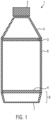
- the Figure 1 shows a container 1 with two horizontally circumferential drawstrings 3, 4.
- the container 1 comprises a shoulder area 5, a side part 6, a base area 8 with a base 7 and an invisible thread that is covered by a lid 2.
- the one horizontally circumferential drawstring 3 connects the shoulder area 5 and the side part 6 and the other horizontally circumferential drawstring 4 connects the side part 6 and the bottom area 8.
- they can serve to ensure the pressure resistance of the container 1, for example when filled with a product containing carbon dioxide.
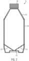
- the Figure 2 shows a container 9 with two oblique drawstrings 11, 12.
- the container 9 includes a shoulder area 13, a side part 14, a base 15 and an invisible thread that is covered by a lid 10.
- the two oblique drawstrings 11, 12 connect the base 15 and the side part 14.
- the oblique drawstrings 11, 12 can prevent the base 15 from curving outwards if, for example, the container 9 is filled with a product containing carbon dioxide.
- the Figure 3 shows a container 16 with two oblique supports 20, 21, a horizontally circumferential tension band 19 and a horizontally circumferential support 18.
- the container 16 comprises a shoulder area 22, a side part 23, a base area 25 with a base 24 and an invisible thread, which is covered by a lid 17.
- the two oblique supports 20, 21 connect the floor area 25 and the shoulder area 22. This allows the stability of the floor 24 to be increased.
- the horizontally circumferential tension band 19 connects the side part 23 and the bottom area 25. This allows the pressure resistance of the container 16 to be increased, for example when filled with a product containing carbon dioxide.
- the horizontally circumferential support 18 connects the shoulder area 22 and the side part 23.
- the support 18 can serve for additional stability when dynamic pressure acts on the container 16 during transport on a conveyor.
- the Figure 4 shows a container 26, the bottom 30 comprising a plurality of segments 32 which are divided by partitions 31.
- a bottom thickness of the segment 32 is smaller than a bottom thickness of a partition 31 of the segments 32.
- the container 26 includes a shoulder area 28, a side part 29, the bottom 30 and an invisible thread that is covered by a lid 27.
- the segment 32 can bulge more and form a base, of which several can be provided along the circumference, for example five. The stability can be increased.
- the containers can alternatively or additionally comprise vertically extending drawstrings which extend at least in some areas along the outer contour of the containers.
- drawstrings two, three, four, five or more bands can be provided along the circumference.
Landscapes
- Engineering & Computer Science (AREA)
- Manufacturing & Machinery (AREA)
- Chemical & Material Sciences (AREA)
- Materials Engineering (AREA)
- Mechanical Engineering (AREA)
- Optics & Photonics (AREA)
- Physics & Mathematics (AREA)
- Ceramic Engineering (AREA)
- Civil Engineering (AREA)
- Composite Materials (AREA)
- Structural Engineering (AREA)
- Auxiliary Devices For And Details Of Packaging Control (AREA)
- Yarns And Mechanical Finishing Of Yarns Or Ropes (AREA)
- Reinforced Plastic Materials (AREA)
Applications Claiming Priority (1)
| Application Number | Priority Date | Filing Date | Title |
|---|---|---|---|
| DE102022121459.1A DE102022121459A1 (de) | 2022-08-25 | 2022-08-25 | Verfahren zum Herstellen eines Fasern umfassenden Behälters und Vorrichtung |
Publications (2)
| Publication Number | Publication Date |
|---|---|
| EP4339364A2 true EP4339364A2 (fr) | 2024-03-20 |
| EP4339364A3 EP4339364A3 (fr) | 2024-04-03 |
Family
ID=86760253
Family Applications (1)
| Application Number | Title | Priority Date | Filing Date |
|---|---|---|---|
| EP23175928.3A Withdrawn EP4339364A3 (fr) | 2022-08-25 | 2023-05-30 | Procédé de fabrication d'un récipient contenant des fibres et dispositif |
Country Status (4)
| Country | Link |
|---|---|
| US (1) | US20240068171A1 (fr) |
| EP (1) | EP4339364A3 (fr) |
| CN (1) | CN117621502A (fr) |
| DE (1) | DE102022121459A1 (fr) |
Family Cites Families (17)
| Publication number | Priority date | Publication date | Assignee | Title |
|---|---|---|---|---|
| DE29512117U1 (de) * | 1995-07-27 | 1995-09-28 | Feldbinder & Beckmann Fahrzeugbau GmbH & Co KG, 21423 Winsen | Tank- oder Silobehälter aus faserverstärkten Kunststoffen |
| US6454906B1 (en) * | 1999-02-18 | 2002-09-24 | Kao Corporation | Process for producing pulp molded article |
| DE10059220C2 (de) | 2000-11-29 | 2002-12-05 | Esther Sellner | Verfahren und Vorrichtung zur Herstellung von Formkörpern aus Papierrohmasse oder dergleichen |
| US6695992B2 (en) * | 2002-01-22 | 2004-02-24 | The University Of Akron | Process and apparatus for the production of nanofibers |
| EP2522772A1 (fr) * | 2011-05-11 | 2012-11-14 | Ecoxpac A/s | Conteneur |
| GB2491605A (en) * | 2011-06-07 | 2012-12-12 | Coca Cola Co | Natural Fibre Composite Vessel |
| DE102013113208A1 (de) * | 2013-11-29 | 2015-06-03 | Rehau Ag + Co. | Verfahren zur Herstellung eines Druckspeichers sowie Druckspeicher |
| PL423754A1 (pl) * | 2017-12-05 | 2019-06-17 | Bibus Menos Spółka Z Ograniczoną Odpowiedzialnością | Sposób wytwarzania obiektów trójwymiarowych |
| US20190240730A1 (en) * | 2018-02-02 | 2019-08-08 | Desktop Metal, Inc. | 3d printing into a liquid medium |
| CN208201496U (zh) * | 2018-05-28 | 2018-12-07 | 重庆大学 | 一种纸浆模型3d打印生产系统 |
| KR102174299B1 (ko) * | 2018-12-18 | 2020-11-04 | 한화솔루션 주식회사 | 3차원 프린팅 방법 및 이에 의한 3차원 프린팅 제품 |
| DE202019102097U1 (de) * | 2019-04-11 | 2020-07-14 | Deutsches Zentrum für Luft- und Raumfahrt e.V. | Faserlegekopf und Faserlegeanlage zum Ablegen von Fasermaterial |
| US12428788B2 (en) | 2019-10-07 | 2025-09-30 | Domtar Paper Company, Llc | Molded pulp products incorporating surface enhanced pulp fibers and methods of making the same |
| CH716689A1 (de) * | 2019-10-10 | 2021-04-15 | Paper Bottle Company As | Faserbasierter Behälter und Verfahren zur Herstellung. |
| CN114786924B (zh) * | 2019-11-25 | 2026-01-23 | 普兰迪斯控股有限公司 | 适合3d打印的组合物 |
| DE102019133809A1 (de) * | 2019-12-10 | 2021-06-10 | Technische Universität Darmstadt | Vorrichtung und Verfahren zur Herstellung einer Faserstruktur |
| US20220135803A1 (en) * | 2020-10-29 | 2022-05-05 | Christoph Klemmt | Material composition for 3d-printing of plant-based fibers |
-
2022
- 2022-08-25 DE DE102022121459.1A patent/DE102022121459A1/de not_active Withdrawn
-
2023
- 2023-05-30 EP EP23175928.3A patent/EP4339364A3/fr not_active Withdrawn
- 2023-07-25 CN CN202310912338.3A patent/CN117621502A/zh active Pending
- 2023-08-04 US US18/365,727 patent/US20240068171A1/en not_active Abandoned
Also Published As
| Publication number | Publication date |
|---|---|
| EP4339364A3 (fr) | 2024-04-03 |
| US20240068171A1 (en) | 2024-02-29 |
| CN117621502A (zh) | 2024-03-01 |
| DE102022121459A1 (de) | 2024-03-07 |
Similar Documents
| Publication | Publication Date | Title |
|---|---|---|
| DE2935304C2 (de) | Laminiertes Verpackungsmaterial mit Faltlinien und Verfahren zu seiner Herstellung | |
| DE202012013166U1 (de) | Biologisch abbaubare Flasche für Flüssigkeiten | |
| DE1090067B (de) | Verfahren zum Verhindern des Klebfaehigwerdens von Teilen einer thermoplastischen Schicht eines Zuschnitts aus Papier, Karton od. dgl. | |
| EP3114038B1 (fr) | Sac en papier et procédé de fabrication d'un tel sac | |
| DE2541912A1 (de) | Behaelter, insbesondere verpackungsbehaelter, daraus aufgebaute verpackungseinheit sowie verfahren und vorrichtung zu seiner herstellung | |
| DE2936138A1 (de) | Doppelwandiger behaelter sowie verfahren und vorrichtung zu dessen herstellung | |
| DE202020101752U1 (de) | Verpackungsmaschine | |
| EP4339364A2 (fr) | Procédé de fabrication d'un récipient contenant des fibres et dispositif | |
| WO2013068116A1 (fr) | Procédé de fabrication de caisses de boissons en matière plastique | |
| DE1436760A1 (de) | Verfahren und Vorrichtung zur Verbindung eines durch Waerme und/oder Druck siegelbaren Materials | |
| EP4194174A1 (fr) | Dispositif pour détacher les sacs internes pliables des parois intérieures de récipients extérieurs rigides | |
| DE3222180C2 (de) | Packung für fließfähige Füllgüter und Verfahren zur Herstellung eines Bodenverschlusses bei dieser Packung | |
| DE594677C (de) | Nahtloser Behaelter aus geformtem Faserstoffbrei mit Verschluss | |
| DE949319C (de) | Aus Papier, Karton od. dgl. bestehende Kettenpackungen und Verfahren zu ihrer Herstellung | |
| DE4017746A1 (de) | Verfahren und vorrichtung zur herstellung von aus gewickeltem und verklebtem kraftpapier bestehenden formstabilen pappkoerpern | |
| DE1761998C3 (de) | Verpackungsbehältnis sowie Verfahren und Vorrichtung zu seiner Herstellung | |
| DE102004049366B3 (de) | Vorrichtung zum Verpressen von mindestens zwei Lagen eines gefalteten Bodens einer Mehrschichtverbundpackung und eine Mehrschichtverbundpackung | |
| DE60108109T3 (de) | Dichthaltend abgeschlossener behälter | |
| DE102022121461A1 (de) | Verfahren zum Herstellen eines Fasern umfassenden Behälters und Vorrichtung zum Ausführen des Verfahrens | |
| DE2209942C3 (de) | Zur Aufnahme mehrerer Behälter bestimmte Transport-und Verkaufspackung | |
| DE2138899A1 (de) | Verfahren und Vorrichtung zum Formen von Verpackungsbehältern | |
| WO2023217895A1 (fr) | Emballage pour un produit, en particulier pour un produit alimentaire | |
| CN113830392A (zh) | 一种纸品包装盒及其生产工艺 | |
| DE3020087A1 (de) | Verfahren zur herstellung einer mit papier gefuetterten schachtel | |
| DE2631715A1 (de) | Verpackung, bestehend aus einem behaelter aus karton und einem deckel aus metallfolie und verfahren zur herstellung einer solchen verpackung |
Legal Events
| Date | Code | Title | Description |
|---|---|---|---|
| PUAI | Public reference made under article 153(3) epc to a published international application that has entered the european phase |
Free format text: ORIGINAL CODE: 0009012 |
|
| STAA | Information on the status of an ep patent application or granted ep patent |
Free format text: STATUS: THE APPLICATION HAS BEEN PUBLISHED |
|
| PUAL | Search report despatched |
Free format text: ORIGINAL CODE: 0009013 |
|
| AK | Designated contracting states |
Kind code of ref document: A2 Designated state(s): AL AT BE BG CH CY CZ DE DK EE ES FI FR GB GR HR HU IE IS IT LI LT LU LV MC ME MK MT NL NO PL PT RO RS SE SI SK SM TR |
|
| AK | Designated contracting states |
Kind code of ref document: A3 Designated state(s): AL AT BE BG CH CY CZ DE DK EE ES FI FR GB GR HR HU IE IS IT LI LT LU LV MC ME MK MT NL NO PL PT RO RS SE SI SK SM TR |
|
| RIC1 | Information provided on ipc code assigned before grant |
Ipc: B29D 22/00 20060101ALI20240228BHEP Ipc: D21J 3/10 20060101ALI20240228BHEP Ipc: B29C 64/20 20170101ALI20240228BHEP Ipc: B29C 64/10 20170101ALI20240228BHEP Ipc: D21J 3/00 20060101AFI20240228BHEP |
|
| STAA | Information on the status of an ep patent application or granted ep patent |
Free format text: STATUS: REQUEST FOR EXAMINATION WAS MADE |
|
| STAA | Information on the status of an ep patent application or granted ep patent |
Free format text: STATUS: THE APPLICATION HAS BEEN WITHDRAWN |
|
| 17P | Request for examination filed |
Effective date: 20241001 |
|
| RBV | Designated contracting states (corrected) |
Designated state(s): AL AT BE BG CH CY CZ DE DK EE ES FI FR GB GR HR HU IE IS IT LI LT LU LV MC ME MK MT NL NO PL PT RO RS SE SI SK SM TR |
|
| 18W | Application withdrawn |
Effective date: 20241017 |