EP4339399B1 - Elément de clôture mobile et clôture modulaire formée de plusieurs éléments de clôture - Google Patents
Elément de clôture mobile et clôture modulaire formée de plusieurs éléments de clôture Download PDFInfo
- Publication number
- EP4339399B1 EP4339399B1 EP22196249.1A EP22196249A EP4339399B1 EP 4339399 B1 EP4339399 B1 EP 4339399B1 EP 22196249 A EP22196249 A EP 22196249A EP 4339399 B1 EP4339399 B1 EP 4339399B1
- Authority
- EP
- European Patent Office
- Prior art keywords
- fence
- base
- channel
- elements
- bases
- Prior art date
- Legal status (The legal status is an assumption and is not a legal conclusion. Google has not performed a legal analysis and makes no representation as to the accuracy of the status listed.)
- Active
Links
Images




Classifications
-
- E—FIXED CONSTRUCTIONS
- E01—CONSTRUCTION OF ROADS, RAILWAYS, OR BRIDGES
- E01F—ADDITIONAL WORK, SUCH AS EQUIPPING ROADS OR THE CONSTRUCTION OF PLATFORMS, HELICOPTER LANDING STAGES, SIGNS, SNOW FENCES, OR THE LIKE
- E01F13/00—Arrangements for obstructing or restricting traffic, e.g. gates, barricades ; Preventing passage of vehicles of selected category or dimensions
- E01F13/02—Arrangements for obstructing or restricting traffic, e.g. gates, barricades ; Preventing passage of vehicles of selected category or dimensions free-standing; portable, e.g. for guarding open manholes ; Portable signs or signals specially adapted for fitting to portable barriers
- E01F13/022—Pedestrian barriers; Barriers for channelling or controlling crowds
-
- E—FIXED CONSTRUCTIONS
- E04—BUILDING
- E04H—BUILDINGS OR LIKE STRUCTURES FOR PARTICULAR PURPOSES; SWIMMING OR SPLASH BATHS OR POOLS; MASTS; FENCING; TENTS OR CANOPIES, IN GENERAL
- E04H17/00—Fencing, e.g. fences, enclosures, corrals
- E04H17/009—Footing elements for fence posts or fence sections
-
- E—FIXED CONSTRUCTIONS
- E04—BUILDING
- E04H—BUILDINGS OR LIKE STRUCTURES FOR PARTICULAR PURPOSES; SWIMMING OR SPLASH BATHS OR POOLS; MASTS; FENCING; TENTS OR CANOPIES, IN GENERAL
- E04H17/00—Fencing, e.g. fences, enclosures, corrals
- E04H17/14—Fences constructed of rigid elements, e.g. with additional wire fillings or with posts
- E04H17/16—Fences constructed of rigid elements, e.g. with additional wire fillings or with posts using prefabricated panel-like elements, e.g. wired frames
- E04H17/161—Fences constructed of rigid elements, e.g. with additional wire fillings or with posts using prefabricated panel-like elements, e.g. wired frames using wire panels
Definitions
- the invention relates to a mobile fence element according to the preamble of patent claim 1 and to a modular barrier fence made up of several such fence elements.
- fence elements are becoming increasingly important and are used, for example, for the temporary shielding of demonstrations or for securing stadiums or ships in ports.
- the particular advantage of such fence elements is their mobility, as they can be set up and dismantled again within a short period of time.
- Several fence elements are connected to one another to form a barrier fence.
- surveillance devices such as cameras or motion sensors have also been increasingly used to identify people approaching the barrier fence.
- surveillance devices require electrical or data cables that must be laid along the barrier fence or along the base.
- fence elements of the generic type for the production of a barrier fence are, for example, from the EP 1 945 888 B1
- the individual, identically constructed fence elements each comprise a base with at least two pillars, between which a sheet-like structure is arranged, with each of the pillars being inserted into a receiving groove or a receiving hole in the base and fixed therein.
- the sheet-like structure is a metal grid.
- the base also has recesses in its bottom area for a lifting device, so that, for example, the lifting fork of an industrial truck can be inserted into these recesses and the fence element can be transported in this way.
- a steel cable is used to connect the individual fence elements to one another, which is guided through eyelets on the outside of the base and whose tension prevents unwanted separation of the individual fence elements of the barrier fence.
- a well-known design of mobile fence elements is, for example, in the DE 10 2015 107 273 B3 described, the solution for connecting the bases can also be used here.
- the CN 208 885 121 U describes a fence element comprising a base made of concrete in the form of a cable trough with two side walls of different heights and enclosing a channel between them, and several pillars supported by the base, between which a surface structure is arranged, each pillar being fixed to the higher side wall.
- the cable trough is open at the top, provided with a cable outlet in the lower side wall and can be covered by a cover. Additional parts can be embedded on the underside of the base, such as square steel or square tubes, to enable the base to be moved with a forklift. Lighting can be provided at the upper end of the pillars
- the invention is based on the object of providing a mobile fence element with a simple structure, whereby a modular barrier fence is formed by connecting several fence elements within a very short time, in which an undesirable separation of the fence elements by unauthorized persons is made difficult or impossible and deliberate damage or destruction of cables or electrical lines for existing monitoring devices is no longer possible.
- a mobile fence element comprising a base with at least one recess for a lifting device and at least two pillars between which a flat structure is arranged, wherein each of the pillars is inserted into a receiving groove or into a receiving bore of the base and fixed therein, was further developed according to the invention in such a way that the base has on one side, on the side of the mobile fence element to be shielded, a channel designed as a receiving groove open transversely to the flat structure for receiving cables or tensioning ropes, which channel extends continuously along the entire length of the base.
- the channel for accommodating the cables which are for example, it can be electrical or data cables or tensioning cables
- the cables or tensioning cables can be laid very easily within the channel. This makes installing the barrier fence easy and time-saving. Since the channels are recessed into the bases of the individual fence elements, they are not accessible from the outside, i.e. from the side to be protected. This means that sabotage of the cables or electrical lines or the tensioning cables can be prevented easily and very effectively.
- the pillars can be fixed in the base using a material fit, a form fit or a force fit. If we consider a material fit between the pillar and the base, we particularly think that the pillars are inserted into the base immediately during manufacture and are connected to the base using a material fit, which can be easily achieved using a casting process for the base, for example.
- a force-fitting connection could, for example, be a fitting connection between the pillar and the base.
- a positive connection between the pillar and the base can be made, for example, using a screw connection, which is in principle detachable.
- the screw connection can be concealed by a toothed connection of the bases arranged adjacent to one another, so that unauthorized loosening can be avoided, which is a very significant advantage.
- security measures are also known for such screw connections, which also prevent unwanted loosening and can be used here if necessary.
- at least one receiving groove is made directly in the base flange and at least one receiving groove is made directly in the engagement contour of the base.
- the bases used can be made from different materials.
- a very simple design variant, for example, is for the bases to be cast from concrete.
- the solution according to the invention can be implemented very easily by forming the channel inside the base during production.
- a first embodiment of the invention involves inserting a profile element into the channel that lines the channel and can be closed with a cover.
- the profile element and the cover can be particularly advantageously simple plastic or aluminum molded parts. The only important thing is that the profile element corresponds to the inner contour of the channel and, just like the cover, has an inner surface that prevents damage to the cables or tensioning cables laid in the channel.
- the cover also ensures that the cables or tensioning cables laid inside the channel are correctly laid and fixed and cannot become undesirably loose from their support created by the channel.
- Such a design of the channel with a profile element and a cover also represents a significant simplification with regard to the assembly of the cables or tensioning cables and thus of the entire barrier fence and brings with it considerable time savings.
- the profile elements can be inserted into the channel of the base in a material-locking manner, for example by means of an adhesive connection or by means of a form-fitting connection.
- an improved embodiment of the invention can be seen in the fact that dowel blocks are inserted into the channel of the base to fix the Profile elements are present.
- the dowel blocks are made of materials that are suitable for screw connections.
- the dowel blocks can be made of wood or hard plastic and, in particularly advantageous versions, have threads that correspond to the screws. This makes it easy to install the profile elements within the channel of a base and can be implemented in a short time.
- the base can be designed as a concrete segment.
- An alternative design variant for the base is that it is a fillable hollow body. This means that the base can be made from sheet metal or plastic, for example, and only filled with sand or similar materials on site so that it reaches the weight required for the safety of the barrier fence. This makes it easier to transport the individual bases or fence elements, as the overall weight of the fence elements is reduced until a barrier fence is made from them.
- the surface structure of the fence element used here can be a panel, a slatted, grid or net structure. If, for example, a panel is used as a surface structure, it can also be used as an advertising medium or to convey information, so that, for example, photographs can be projected onto such a panel. A panel also provides optimal privacy protection.
- the base has a base flange on one of its front sides and a has an engagement contour so that the base flange of one of at least two interconnected fence elements can be inserted in a form-fitting manner into the engagement contour of another fence element arranged adjacent to this fence element.
- the form-fitting connection ensures that the fence elements cannot be separated from the side to be protected, even with the use of tools and/or force.
- a special embodiment of the solution described above consists in the fact that the base flange and the engagement contour of two adjacent fence elements are designed to engage with one another in a toothed manner. Since the base is crucial for the stability of the fence element and thus of the entire barrier fence, it has a suitable weight that must be sufficient to absorb or counteract forces acting on the fence system, such as those caused by wind or the impact of force. The high weight of the base also has the advantage that the individual fence elements cannot be easily separated from one another. If the toothed connection mentioned above is also provided, this can improve the connection between the bases and prevent unwanted separation of the fence system by unauthorized persons.
- a modular barrier fence consists of several interconnected, mobile fence elements, as previously described in detail. It is particularly important that the channels of two adjacent and interconnected fence elements are directly adjacent to one another, thus forming a continuous channel along the barrier fence.
- the open design of the channel means that a single fence element can also be easily removed from the barrier fence and replaced with a new fence element. This simply requires opening the channel in the affected section (provided it is closed with a lid) and removing the cable or tensioning rope from the channel. No further work is therefore required for the repair or replacement.
- the barrier fence according to the invention has other, very important features.
- the barrier fence has at least one camera base on the side to be shielded, with engagement geometries corresponding to the bases, which is equipped with a mast for monitoring devices and/or with a control cabinet.
- the camera base has cable routing channels to continue the channels of the base.
- This means that such a camera base has the same features as the bases of the other fence elements.
- the camera base can also have pillars and a surface structure arranged between the pillars in the sense of the previously described fence elements. This means that the camera base can be easily integrated into the barrier fence without any additional expenditure.
- the cable routing channels consist of pipes inserted or molded into the camera base. These are preferably plastic pipes, as these avoid the risk of damage to the installed cables.
- a barrier fence has corner bases in corner areas with channels corresponding to the bases or camera bases and with corresponding engagement contours, which enable two fence elements to be connected at an angle, preferably at a right angle, to one another.
- This simple method not only enables a straight design of the barrier fence, but it can also be built around corners. This makes the barrier fence very flexible overall and adaptable to different local conditions.
- the barrier fence has left and right corner bases in order to further improve the previously described flexibility of its design.
- the design of the channels of the corner bases and the camera bases it is also sensible for the design of the channels of the corner bases and the camera bases to provide an adhesive connection or dowel blocks for fixing the profile elements so that profile elements can also be inserted into these channels, which can be closed with suitable covers.
- the Pillars viewed in the longitudinal direction of the barrier fence, have a Y-shape.
- the spread created by the Y-shape in the upper end area of the pillars allows for a simplified insertion of the barbed wire, which is provided in prefabricated rolls and thus has a spiral shape.
- the barbed wire or NATO wire is thus simply inserted into the Y-shape of the pillars.
- the aforementioned design of the base with recesses on the floor allows, for example, the use of an industrial truck, the lifting fork of which can be inserted directly into the recesses to enable the transport of the fence elements and the assembly of the barrier fence from several fence elements.
- the lifting device can be an industrial truck or a crane.
- the camera bases and the corner bases also have at least one recess for a lifting device.
- hooks or eyelets can of course also be incorporated into the base. Hooks or eyelets incorporated into the base in particular can be used for transport by means of a crane, on the boom of which there are carrying devices compatible with the hooks or eyelets.
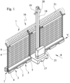
- FIG. 1 a spatial representation of a barrier fence 16 consisting of several fence elements 1 is shown.
- the barrier fence 16 is made up of several fence elements 1 of different lengths, which in turn consist of a base 2 on the ground, which in the example shown has receiving grooves 7 on its front ends, into which pillars 4 and 5 are inserted and fixed in place. Between the pillars 4 and 5 there is also a surface structure 6, which is a steel grid. Viewed in the longitudinal direction of the barrier fence 16, the pillars 4, 5 each have a Y-shape, so that a barbed wire 31 can be inserted into the resulting gap, which prevents the barrier fence 16 from being climbed over.
- the barrier fence 16 also has various monitoring devices that are attached to the upper end of a mast 18.
- a motion sensor 19 and a monitoring device are indicated there. or infrared or thermal camera 20.
- the monitoring devices 19, 20 require electrical cables or data cables that must be laid inside the mast 18 and also along the barrier fence 16, namely on the side opposite the area to be shielded.
- a channel 8 designed as an open receiving groove is introduced into the base 2 of the fence elements 1, which is lined with profile elements 10 in a manner described in more detail below to prevent damage to the electrical or data cables.
- This control cabinet 21 is used in the Figure 1 shown embodiment of a barrier fence 16 is arranged on a camera base 17, which also accommodates the mast 18.
- the fence element on which the control cabinet 21 is arranged has a smaller width than the other fence elements 1 of the barrier fence 16 shown. Since the bases 2 of the fence elements 1 are usually cast from a concrete material, the channel 8, which is open to the outside, can be easily inserted into the base 2 during its manufacture.
- each existing base 2 has recesses 3 on its bottom side, which are designed for the engagement of a lifting device.
- the lifting device can be, for example, an industrial truck, i.e. a forklift truck, the forks of which engage in the recesses 3 in order to be able to lift and transport the corresponding fence element 1. This also results in the mobility of the individual fence element 1.
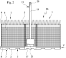
- FIG. 2 illustrates the context of the description of the Figure 1 shown barrier fence 16 in a perspective corresponding to arrow II of Figure 1 corresponds.
- a base 2 of a fence element 1 is shown as a separate individual part in a side view. From this view it is clear that the channel 8 is designed as an open receiving groove. In the illustration of the Figure 3 no profile elements 10 are inserted into the channel 8, so that the dowel blocks 11 inserted therein are visible.
- the dowel blocks 11 are used to fasten the profile elements 10 in the channel. They facilitate the fixing of the profile elements 10 with screws or other fastening means, such as clamps or rivets.
- the dowel blocks 11 can be made of hard plastic or wood, for example. When the base 2 is made of concrete, the dowel blocks 11 are already inserted into the base 2 during the casting process.
- the base 2 also has different engagement geometries on its front sides 12 and 13.
- a base flange 14 is formed on the front side 12, while an engagement contour 15 in the form of a recessed geometry matching the base flange 14 is provided on the front side 13.
- several bases 2 can be coupled together in a form-fitting manner in the longitudinal direction, whereby the connection can also be designed in a toothed manner.
- FIG. 4 a view in the direction of arrow IV Figure 3 on the base 2.
- the illustration illustrates in an improved manner the described engagement geometry of the base 2, consisting of engagement contours 15 and base flanges 14, which engage with each other when several bases 2 are arranged in a row.
- the previously described grooves 7 for inserting pillars 4 and 5 are also clearly visible.
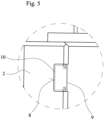
- the Figure 5 allows a view of a channel 8 equipped with a profile element 10 and a cover 9 in a sectional view according to the direction of arrow V from Figure 2
- the profile element 10 has an external geometry corresponding to the cross-section of the channel 8, so that it can be easily inserted into the channel 8. With the help of the dowel blocks 11 described above, a reliable fixation of the profile element 10 in the channel 8 is also possible.
- the channel 8 is closed by the cover 9.
- the profile element 10 and the cover 9 have corresponding engagement geometries.
- the Figure 6 shows a profile element 10 for use in a channel 8.
- This is a one-piece plastic or aluminum molded part with a U-shaped cross-section.
- the profile element 10 has two vertical legs 25 on the side, each of which has a groove 26 on the outside at its outer ends, which merges into a hook-shaped contour 27.
- the end sections of the vertical legs 25 each have a corrugated structure 28.
- the cover 9 shown is suitable for the profile element 10 according to Figure 6 designed so that it has a leg on its underside, which is not visible when assembled, which has a corrugated structure 29 corresponding to the corrugated structure 28 of the profile element 10.
- the claw 30 also formed on the cover 9 engages in the groove 26 of the profile element 10 when the cover 9 is assembled.
- the description of the Figure 1 The camera base 17 mentioned above is available in a not yet cast version in the Figure 8 This allows a view into the hollow interior of the camera base 17, from which it can be seen that it has various cable routing channels 22 that are used to guide electrical or data cables to the control cabinet 21 or to the mast 18.
- dowel blocks 11 or screw sleeves can also be provided in order to be able to mount the control cabinet 21 on the camera base in a simplified manner after the camera base 17 has been completed.
- the camera base 17 also has several recesses 3 on its bottom side, which serve to engage the lifting forks of a lifting device.
- the illustration of the Figure 8 also shows that the camera base 17 with engagement contours 14 and 15, which enable a direct coupling with the bases 2 of the barrier fence 16.
- FIGS 9 and 10 two special design variants of bases.
- corner bases 23 and 24 which as the so-called left version and right version allow the barrier fence 16 to be guided at an angle, preferably at a right angle, so that fence corners can also be created.
- the corner bases 23 and 24 also have suitable engagement contours 14 and 15 in order to be able to be connected to the bases 2.
- Dowel blocks 11 are also provided in the channel 8 which can be seen in outline.
Landscapes
- Engineering & Computer Science (AREA)
- Architecture (AREA)
- Civil Engineering (AREA)
- Structural Engineering (AREA)
- Fencing (AREA)
Claims (17)
- Élément de clôture mobile (1), comprenant un socle (2) avec au moins un évidement (3) pour un dispositif de levage et au moins deux piliers (4, 5), entre lesquels est agencée une structure plane (6), chacun des piliers (4, 5) étant inséré et fixé dans une rainure de réception (7) ou dans un alésage de réception du socle (2), caractérisé en ce que
le socle (2) présentant d'un côté, sur le côté à protéger de l'élément de clôture mobile (1), un canal (8) réalisé sous la forme d'une rainure de réception ouverte transversalement à la structure plane (6) destinée à recevoir des câbles ou des câbles tendeurs, qui s'étend en continu sur toute la longueur du socle (2). - Élément de clôture mobile selon la revendication 1,
caractérisé en ce que
un élément profilé (10) recouvrant le canal (8) et pouvant être fermé par un couvercle (9) est inséré dans le canal (8). - Élément de clôture mobile selon la revendication 2,
caractérisé en ce que
lorsque le canal (8) est fermé, le couvercle (9) est relié par complémentarité de forme ou par liaison de force à l'élément profilé (10). - Élément de clôture mobile selon la revendication 2 ou 3,
caractérisé en ce que
des blocs de cheville (11) sont présents dans le canal (8) du socle (2) pour la fixation des éléments profilés (10) ou la fixation des éléments profilés (10) dans le canal (8) s'effectue au moyen d'une liaison par complémentarité de matière. - Élément de clôture mobile selon l'une quelconque des revendications précédentes,
caractérisé en ce que
le socle (2) est conçu sous la forme d'un segment en béton ou d'un corps creux remplissable. - Élément de clôture mobile selon l'une quelconque des revendications précédentes,
caractérisé en ce que
la structure plane (6) est une plaque, une structure à lattes, en treillis ou en filet. - Élément de clôture mobile selon l'une quelconque des revendications précédentes,
caractérisé en ce que
le socle (2) présente une bride de socle (14) sur l'une de ses faces frontales (12) et un contour de mise en prise (15) sur la face frontale (13) opposée à la bride de socle (14), de sorte que la bride de socle (14) de l'un d'au moins deux éléments de clôture reliés entre eux peut être insérée par complémentarité de forme dans le contour de mise en prise (15) d'un élément de clôture supplémentaire agencé de manière adjacente par rapport à cet élément de clôture. - Élément de clôture mobile selon la revendication 7,
caractérisé en ce que
la bride de socle (14) et le contour de mise en prise (15) de deux éléments de clôture agencés adjacents l'un par rapport à l'autre sont conçus pour une mise en prise l'un dans l'autre. - Clôture-barrière modulaire (16) constituée de plusieurs éléments de clôture mobiles (1) reliés entre eux selon l'une quelconque des revendications précédentes,
caractérisée en ce que
les canaux (8) dans les socles (2) reliés par complémentarité de forme de deux éléments de clôture (1) reliés l'un à l'autre sont directement limitrophes l'un par rapport à l'autre, et un canal continu (8) est ainsi formé le long de la clôture-barrière (16). - Clôture-barrière modulaire selon la revendication 9,
caractérisée en ce que
la clôture (16) présente sur son côté à protéger au moins un socle de caméra (17) avec des géométries de mise en prise (14, 15) correspondant aux socles (2), qui est équipé d'un mât (18) pour des appareils de surveillance (19, 20) et/ou d'un boîtier de commande (21). - Clôture-barrière modulaire selon la revendication 10,
caractérisée en ce que
le socle de caméra (17) présente des canaux de guidage de ligne (22) pour la poursuite des canaux (8) du socle (2). - Clôture-barrière modulaire selon la revendication 11,
caractérisée en ce que
les canaux de guidage de ligne (22) sont constitués de tuyaux insérés ou moulés dans les socles de caméra (17). - Clôture-barrière modulaire selon l'une quelconque des revendications 9 à 12,
caractérisée en ce que
dans les zones d'angle de la clôture (16) sont présents des socles d'angle (23, 24) avec des canaux (8) correspondant aux socles (2) et avec des contours de mise en prise (14, 15) qui permettent le raccordement latéral de deux éléments de clôture (1) selon un angle l'un par rapport à l'autre. - Clôture-barrière modulaire selon l'une quelconque des revendications 9 à 13,
caractérisée en ce que
des socles d'angle gauche et droit (23, 24) sont présents. - Clôture-barrière modulaire selon l'une quelconque des revendications 9 à 14,
caractérisée en ce que
dans les canaux (8) des socles d'angle (23, 24) et des socles de caméra (17) sont présents des blocs de cheville (11) pour la fixation des éléments profilés (10) ou la fixation des éléments profilés (10) dans le canal (8) s'effectue au moyen d'une liaison par complémentarité de matière. - Clôture-barrière modulaire selon l'une quelconque des revendications 9 à 15,
caractérisée en ce que
les piliers (4, 5), vus dans la direction longitudinale de la clôture, présentent une forme en Y. - Clôture-barrière modulaire selon l'une quelconque des revendications 9 à 16,
caractérisée en ce que
les socles de caméra (17) et les socles d'angle (23, 24) présentent au moins un évidement (3) pour un dispositif de levage.
Priority Applications (5)
| Application Number | Priority Date | Filing Date | Title |
|---|---|---|---|
| PL22196249.1T PL4339399T3 (pl) | 2022-09-16 | 2022-09-16 | Ruchomy element ogrodzeniowy i zbudowane modułowo ogrodzenie barierowe, utworzone z kilku tego rodzaju elementów ogrodzeniowych |
| EP22196249.1A EP4339399B1 (fr) | 2022-09-16 | 2022-09-16 | Elément de clôture mobile et clôture modulaire formée de plusieurs éléments de clôture |
| EP23197772.9A EP4339400B1 (fr) | 2022-09-16 | 2023-09-15 | Elément de clôture mobile et clôture modulaire formée de plusieurs éléments de clôture |
| PCT/EP2023/075505 WO2024056887A1 (fr) | 2022-09-16 | 2023-09-15 | Élément de clôture mobile et clôture-barrière construite de manière modulaire, formée à partir de plusieurs éléments de clôture de ce type |
| PL23197772.9T PL4339400T3 (pl) | 2022-09-16 | 2023-09-15 | Ruchomy element ogrodzeniowy i zbudowane modułowo ogrodzenie barierowe, utworzone z kilku tego rodzaju elementów ogrodzeniowych |
Applications Claiming Priority (1)
| Application Number | Priority Date | Filing Date | Title |
|---|---|---|---|
| EP22196249.1A EP4339399B1 (fr) | 2022-09-16 | 2022-09-16 | Elément de clôture mobile et clôture modulaire formée de plusieurs éléments de clôture |
Publications (3)
| Publication Number | Publication Date |
|---|---|
| EP4339399A1 EP4339399A1 (fr) | 2024-03-20 |
| EP4339399B1 true EP4339399B1 (fr) | 2025-02-19 |
| EP4339399C0 EP4339399C0 (fr) | 2025-02-19 |
Family
ID=83362455
Family Applications (2)
| Application Number | Title | Priority Date | Filing Date |
|---|---|---|---|
| EP22196249.1A Active EP4339399B1 (fr) | 2022-09-16 | 2022-09-16 | Elément de clôture mobile et clôture modulaire formée de plusieurs éléments de clôture |
| EP23197772.9A Active EP4339400B1 (fr) | 2022-09-16 | 2023-09-15 | Elément de clôture mobile et clôture modulaire formée de plusieurs éléments de clôture |
Family Applications After (1)
| Application Number | Title | Priority Date | Filing Date |
|---|---|---|---|
| EP23197772.9A Active EP4339400B1 (fr) | 2022-09-16 | 2023-09-15 | Elément de clôture mobile et clôture modulaire formée de plusieurs éléments de clôture |
Country Status (3)
| Country | Link |
|---|---|
| EP (2) | EP4339399B1 (fr) |
| PL (2) | PL4339399T3 (fr) |
| WO (1) | WO2024056887A1 (fr) |
Family Cites Families (5)
| Publication number | Priority date | Publication date | Assignee | Title |
|---|---|---|---|---|
| AUPQ277499A0 (en) * | 1999-09-10 | 1999-10-07 | Mathias, Andrew | Walling assembly and method |
| FR2891567B1 (fr) | 2005-09-30 | 2007-12-07 | Dirickx Groupe Sa | Barriere |
| DE102015107273B3 (de) | 2015-05-11 | 2016-10-27 | Thomas Bockmeyer | Zaunanlage |
| CN208885121U (zh) * | 2018-08-02 | 2019-05-21 | 上海城投公路管理有限公司 | 一种凹槽型围挡 |
| CN209799566U (zh) * | 2019-03-05 | 2019-12-17 | 胡安保 | 一种建筑施工围挡护栏 |
-
2022
- 2022-09-16 PL PL22196249.1T patent/PL4339399T3/pl unknown
- 2022-09-16 EP EP22196249.1A patent/EP4339399B1/fr active Active
-
2023
- 2023-09-15 EP EP23197772.9A patent/EP4339400B1/fr active Active
- 2023-09-15 PL PL23197772.9T patent/PL4339400T3/pl unknown
- 2023-09-15 WO PCT/EP2023/075505 patent/WO2024056887A1/fr not_active Ceased
Also Published As
| Publication number | Publication date |
|---|---|
| EP4339400C0 (fr) | 2025-01-29 |
| EP4339400A1 (fr) | 2024-03-20 |
| WO2024056887A1 (fr) | 2024-03-21 |
| EP4339399C0 (fr) | 2025-02-19 |
| EP4339400B1 (fr) | 2025-01-29 |
| PL4339400T3 (pl) | 2025-06-09 |
| EP4339399A1 (fr) | 2024-03-20 |
| WO2024056887A4 (fr) | 2024-04-18 |
| PL4339399T3 (pl) | 2025-09-01 |
Similar Documents
| Publication | Publication Date | Title |
|---|---|---|
| DE60311366T2 (de) | Betonbodenplatte | |
| EP0258338A1 (fr) | Pieces de fixation pour structures coffrees en beton | |
| EP2453544A2 (fr) | Cabine souterraine | |
| EP4114777B1 (fr) | Dispositif de protection lors des travaux de montage sur un escalier ou une marche mobile | |
| EP2499311B1 (fr) | Grille de protection latérale et système de protection latérale | |
| EP0785385B1 (fr) | Goulotte de câbles en matière plastique | |
| DE102012101366B3 (de) | Unterflur-Schacht, Bausatz zum Herstellen und Verfahren zum Einbau dafür | |
| EP4339399B1 (fr) | Elément de clôture mobile et clôture modulaire formée de plusieurs éléments de clôture | |
| DE3714053C2 (de) | Aufzug für Personentransport | |
| EP3436638B1 (fr) | Structure de transition servant au pontage d'un joint de construction | |
| WO2014005581A2 (fr) | Système anti-foule | |
| DE102009037977A1 (de) | Absperrelement, insbesondere ein Bauzaun, eine Absperrschranke oder dgl., Vorrichtung zur Verkettung von Absperrelementen und Schwenkvorrichtung zwischen zwei Absperrelementen | |
| AT408561B (de) | Schutzzaun | |
| EP2565328B1 (fr) | Barrière de séparation de voie ainsi que système de retenue de véhicule avec barrière de séparation de voie | |
| EP1724400A1 (fr) | Coffrage des canaux | |
| EP0778378B1 (fr) | Dispositif de sécurité pour ouvertures de toit et procédé de fabrication de ce dispositif | |
| DE102015107273B3 (de) | Zaunanlage | |
| DE20312406U1 (de) | Anordnung zur Errichtung von ein- oder mehrgeschossigen Gebäuden | |
| DE102012105274A1 (de) | Unterirdischer Schaltschrank für die Elektroinstallation | |
| DE19703835C2 (de) | Personenführung für Selbstbedienungsmärkte oder dergleichen | |
| DE10001621C2 (de) | Bausatz für ein (Kompakt-)Stationsgebäude | |
| WO2009124519A1 (fr) | Système de retenue pour véhicule | |
| EP2336446A2 (fr) | Elément de coffrage articulé pour joints | |
| DE202025102116U1 (de) | An einer Stabgittermatte ausgebildeter Kabelkanal | |
| DE10302284B4 (de) | Verbauvorrichtung und Verbauplatte sowie Kammerplatte hierfür |
Legal Events
| Date | Code | Title | Description |
|---|---|---|---|
| PUAI | Public reference made under article 153(3) epc to a published international application that has entered the european phase |
Free format text: ORIGINAL CODE: 0009012 |
|
| STAA | Information on the status of an ep patent application or granted ep patent |
Free format text: STATUS: THE APPLICATION HAS BEEN PUBLISHED |
|
| AK | Designated contracting states |
Kind code of ref document: A1 Designated state(s): AL AT BE BG CH CY CZ DE DK EE ES FI FR GB GR HR HU IE IS IT LI LT LU LV MC MK MT NL NO PL PT RO RS SE SI SK SM TR |
|
| STAA | Information on the status of an ep patent application or granted ep patent |
Free format text: STATUS: REQUEST FOR EXAMINATION WAS MADE |
|
| RIN1 | Information on inventor provided before grant (corrected) |
Inventor name: TILLMANN, MARKUS Inventor name: SCHROYEN, JUERGEN Inventor name: BOCKMEYER, THOMAS |
|
| 17P | Request for examination filed |
Effective date: 20240528 |
|
| RBV | Designated contracting states (corrected) |
Designated state(s): AL AT BE BG CH CY CZ DE DK EE ES FI FR GB GR HR HU IE IS IT LI LT LU LV MC MK MT NL NO PL PT RO RS SE SI SK SM TR |
|
| REG | Reference to a national code |
Ref country code: DE Ref legal event code: R079 Free format text: PREVIOUS MAIN CLASS: E04H0017180000 Ref country code: DE Ref legal event code: R079 Ref document number: 502022002927 Country of ref document: DE Free format text: PREVIOUS MAIN CLASS: E04H0017180000 Ipc: E04H0017000000 |
|
| GRAP | Despatch of communication of intention to grant a patent |
Free format text: ORIGINAL CODE: EPIDOSNIGR1 |
|
| STAA | Information on the status of an ep patent application or granted ep patent |
Free format text: STATUS: GRANT OF PATENT IS INTENDED |
|
| RIC1 | Information provided on ipc code assigned before grant |
Ipc: E01F 13/02 20060101ALI20240911BHEP Ipc: E01F 13/12 20060101ALI20240911BHEP Ipc: E04H 17/16 20060101ALI20240911BHEP Ipc: E04H 17/18 20060101ALI20240911BHEP Ipc: E04H 17/00 20060101AFI20240911BHEP |
|
| INTG | Intention to grant announced |
Effective date: 20240920 |
|
| GRAS | Grant fee paid |
Free format text: ORIGINAL CODE: EPIDOSNIGR3 |
|
| GRAA | (expected) grant |
Free format text: ORIGINAL CODE: 0009210 |
|
| STAA | Information on the status of an ep patent application or granted ep patent |
Free format text: STATUS: THE PATENT HAS BEEN GRANTED |
|
| AK | Designated contracting states |
Kind code of ref document: B1 Designated state(s): AL AT BE BG CH CY CZ DE DK EE ES FI FR GB GR HR HU IE IS IT LI LT LU LV MC MK MT NL NO PL PT RO RS SE SI SK SM TR |
|
| REG | Reference to a national code |
Ref country code: GB Ref legal event code: FG4D Free format text: NOT ENGLISH |
|
| REG | Reference to a national code |
Ref country code: CH Ref legal event code: EP |
|
| REG | Reference to a national code |
Ref country code: DE Ref legal event code: R096 Ref document number: 502022002927 Country of ref document: DE |
|
| REG | Reference to a national code |
Ref country code: IE Ref legal event code: FG4D Free format text: LANGUAGE OF EP DOCUMENT: GERMAN |
|
| U01 | Request for unitary effect filed |
Effective date: 20250311 |
|
| U07 | Unitary effect registered |
Designated state(s): AT BE BG DE DK EE FI FR IT LT LU LV MT NL PT RO SE SI Effective date: 20250318 |
|
| PG25 | Lapsed in a contracting state [announced via postgrant information from national office to epo] |
Ref country code: RS Free format text: LAPSE BECAUSE OF FAILURE TO SUBMIT A TRANSLATION OF THE DESCRIPTION OR TO PAY THE FEE WITHIN THE PRESCRIBED TIME-LIMIT Effective date: 20250519 |
|
| PG25 | Lapsed in a contracting state [announced via postgrant information from national office to epo] |
Ref country code: ES Free format text: LAPSE BECAUSE OF FAILURE TO SUBMIT A TRANSLATION OF THE DESCRIPTION OR TO PAY THE FEE WITHIN THE PRESCRIBED TIME-LIMIT Effective date: 20250219 |
|
| PG25 | Lapsed in a contracting state [announced via postgrant information from national office to epo] |
Ref country code: IS Free format text: LAPSE BECAUSE OF FAILURE TO SUBMIT A TRANSLATION OF THE DESCRIPTION OR TO PAY THE FEE WITHIN THE PRESCRIBED TIME-LIMIT Effective date: 20250619 |
|
| PG25 | Lapsed in a contracting state [announced via postgrant information from national office to epo] |
Ref country code: HR Free format text: LAPSE BECAUSE OF FAILURE TO SUBMIT A TRANSLATION OF THE DESCRIPTION OR TO PAY THE FEE WITHIN THE PRESCRIBED TIME-LIMIT Effective date: 20250219 |
|
| REG | Reference to a national code |
Ref country code: SK Ref legal event code: T3 Ref document number: E 46470 Country of ref document: SK |
|
| PG25 | Lapsed in a contracting state [announced via postgrant information from national office to epo] |
Ref country code: GR Free format text: LAPSE BECAUSE OF FAILURE TO SUBMIT A TRANSLATION OF THE DESCRIPTION OR TO PAY THE FEE WITHIN THE PRESCRIBED TIME-LIMIT Effective date: 20250520 |
|
| REG | Reference to a national code |
Ref country code: CH Ref legal event code: U11 Free format text: ST27 STATUS EVENT CODE: U-0-0-U10-U11 (AS PROVIDED BY THE NATIONAL OFFICE) Effective date: 20251001 |
|
| PG25 | Lapsed in a contracting state [announced via postgrant information from national office to epo] |
Ref country code: SM Free format text: LAPSE BECAUSE OF FAILURE TO SUBMIT A TRANSLATION OF THE DESCRIPTION OR TO PAY THE FEE WITHIN THE PRESCRIBED TIME-LIMIT Effective date: 20250219 |
|
| U20 | Renewal fee for the european patent with unitary effect paid |
Year of fee payment: 4 Effective date: 20250901 |
|
| PGFP | Annual fee paid to national office [announced via postgrant information from national office to epo] |
Ref country code: NO Payment date: 20250902 Year of fee payment: 4 |
|
| PGFP | Annual fee paid to national office [announced via postgrant information from national office to epo] |
Ref country code: PL Payment date: 20250902 Year of fee payment: 4 |
|
| PGFP | Annual fee paid to national office [announced via postgrant information from national office to epo] |
Ref country code: CZ Payment date: 20250903 Year of fee payment: 4 Ref country code: IE Payment date: 20250901 Year of fee payment: 4 |
|
| PGFP | Annual fee paid to national office [announced via postgrant information from national office to epo] |
Ref country code: SK Payment date: 20250910 Year of fee payment: 4 |
|
| PLBE | No opposition filed within time limit |
Free format text: ORIGINAL CODE: 0009261 |
|
| STAA | Information on the status of an ep patent application or granted ep patent |
Free format text: STATUS: NO OPPOSITION FILED WITHIN TIME LIMIT |
|
| PGFP | Annual fee paid to national office [announced via postgrant information from national office to epo] |
Ref country code: CH Payment date: 20251001 Year of fee payment: 4 |
|
| 26N | No opposition filed |
Effective date: 20251120 |