EP4339416B1 - Agencements de rinçage et de raccordement pour outils de forage à percussion - Google Patents
Agencements de rinçage et de raccordement pour outils de forage à percussion Download PDFInfo
- Publication number
- EP4339416B1 EP4339416B1 EP24155400.5A EP24155400A EP4339416B1 EP 4339416 B1 EP4339416 B1 EP 4339416B1 EP 24155400 A EP24155400 A EP 24155400A EP 4339416 B1 EP4339416 B1 EP 4339416B1
- Authority
- EP
- European Patent Office
- Prior art keywords
- bit
- percussion
- drive ring
- wear sleeve
- drill tool
- Prior art date
- Legal status (The legal status is an assumption and is not a legal conclusion. Google has not performed a legal analysis and makes no representation as to the accuracy of the status listed.)
- Active
Links
Images






Classifications
-
- E—FIXED CONSTRUCTIONS
- E21—EARTH OR ROCK DRILLING; MINING
- E21B—EARTH OR ROCK DRILLING; OBTAINING OIL, GAS, WATER, SOLUBLE OR MELTABLE MATERIALS OR A SLURRY OF MINERALS FROM WELLS
- E21B1/00—Percussion drilling
- E21B1/12—Percussion drilling with a reciprocating impulse member
- E21B1/24—Percussion drilling with a reciprocating impulse member the impulse member being a piston driven directly by fluid pressure
- E21B1/30—Percussion drilling with a reciprocating impulse member the impulse member being a piston driven directly by fluid pressure by air, steam or gas pressure
-
- E—FIXED CONSTRUCTIONS
- E21—EARTH OR ROCK DRILLING; MINING
- E21B—EARTH OR ROCK DRILLING; OBTAINING OIL, GAS, WATER, SOLUBLE OR MELTABLE MATERIALS OR A SLURRY OF MINERALS FROM WELLS
- E21B1/00—Percussion drilling
- E21B1/38—Hammer piston type, i.e. in which the tool bit or anvil is hit by an impulse member
-
- E—FIXED CONSTRUCTIONS
- E21—EARTH OR ROCK DRILLING; MINING
- E21B—EARTH OR ROCK DRILLING; OBTAINING OIL, GAS, WATER, SOLUBLE OR MELTABLE MATERIALS OR A SLURRY OF MINERALS FROM WELLS
- E21B10/00—Drill bits
- E21B10/36—Percussion drill bits
-
- E—FIXED CONSTRUCTIONS
- E21—EARTH OR ROCK DRILLING; MINING
- E21B—EARTH OR ROCK DRILLING; OBTAINING OIL, GAS, WATER, SOLUBLE OR MELTABLE MATERIALS OR A SLURRY OF MINERALS FROM WELLS
- E21B4/00—Drives for drilling, used in the borehole
- E21B4/06—Down-hole impacting means, e.g. hammers
- E21B4/14—Fluid operated hammers
Definitions
- the present invention relates to flushing and connection arrangements for fluid-operated percussion drill tools.
- the invention concerns flushing and connection arrangements for use in down-the-hole hammers.
- Percussion bits for fluid-operated percussion drill tools typically comprise a bit head, populated with cutting inserts on the front face of the head.
- the bit head is formed with an axially extending shank having a smaller diameter than the bit head.
- rotational drive is most commonly transmitted to the shank by way of splines provided on the external cylindrical wall of the shank which mate with splines provided internally of a drive chuck of the drill tool.
- an impact piston collides with a rear end of the shank, forcing the cutting inserts on the bit head into the rock being drilled.
- flushing air Pressurised air, known as flushing air, is used to flush cuttings out of the hole while the hammer operates. Flushing air may be provided via a flushing bore through the centre of the piston and a corresponding bore through the bit shank.
- this arrangement typically requires a footvalve, which can be prone to breakage, to control the flushing air.
- the strike area of the piston is reduced due to the central bore, which also reduces the weight of the piston.
- the area of the lifting surface of the piston is also reduced.
- An alternative is to have the flushing air travel along the splines, with channels provided in the bit head to direct the air from the splines to the cutting face of the bit. As the splines require lubrication, lubricating oil may be added to the flushing air stream at the drill rig.
- Irish Patent No. S87042 proposes an alternative arrangement to the conventional splined engagement between the drive means of the drill tool and the bit, in which a drive ring is provided with a plurality of protrusions at a forward end therefore, each of which is received in one of a corresponding plurality of recesses on the bit head. Because the engagement means are provided at the head portion of the bit, the length of the bit may be reduced, thereby reducing the overall weight of the bit, enabling faster and more efficient drilling. It is desirable to provide a flushing arrangement for use with this drive mechanism, and others, that allows for increased piston weight and strike area and that optimises the piston to bit mass ratio.
- United States Patent No. 3,387,671 relates to a percussion tool.
- United States Patent No. 6,702,045 relates to a drilling apparatus.
- a fluid-operated percussion drill tool comprising:
- a bit retaining ring may be arranged to engage with the bit retaining portion of the percussion bit to retain the bit in the percussion drill tool.
- the bit retaining ring may be clamped in place between the drive ring and an aligner by engagement of the fasteners with the drive ring.
- the bit retaining ring may be provided as a plurality of part-annular bit retaining portions and the depth of the holes in the collar of the drive ring may be greater than a height of the bit retaining portions such that the percussion bit is removable from the drill tool by withdrawing the fasteners from the holes by a distance greater than or equal to the height of the bit retaining portions but less than the depth of the holes such that when the outer wear sleeve is moved away from the percussion bit, an annular space is formed between the forward end of the wear sleeve and the internal shoulder of the drive ring, into which the bit retaining portions are moveable in a radially outward direction such that they no longer retain the percussion bit in the drill tool.
- the fluid-operated percussion drill tool may further comprise an O-ring arranged around the bit retaining portions.
- the fluid-operated percussion drill tool may comprise a plurality of pins extending through the drive ring and arranged to engage the bit retaining portions.
- a method for removing a percussion drill bit from a fluid-operated percussion drill tool as set out above comprising:
- the method may be further for replacing the percussion drill bit, and may further comprise:
- the fluid-operated percussion drill tool is a down-the-hole hammer.
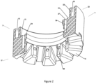
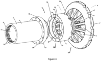
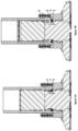
- a down-the-hole hammer 1 according to a first embodiment of the present invention is illustrated in Figures 1 to 5 .
- the hammer 1 comprises an outer wear sleeve 2 comprising a substantially cylindrical wall 3 and having inner 4 and outer 5 surfaces.
- the hammer also comprises a percussion bit 6 having a head portion 7 and a bit retaining shoulder 8.
- the bit is located at a forward end 9 of the outer wear sleeve.
- the hammer further comprises a sliding piston 10 mounted for reciprocating movement within the outer wear sleeve to strike the percussion bit.
- a drive ring 11 having a substantially cylindrical wall 12 comprises connection means 13 adapted for connecting the drive ring to a drive means of the hammer.
- a bit retaining ring 21 is arranged to engage with the bit retaining shoulder 8 on the percussion bit to retain the bit in the hammer.
- a plurality of recesses 14 are provided at a rear end 15 of the head portion 7 of the percussion bit 6.
- a corresponding plurality of protrusions 16 is provided at a forward end 17 of the drive ring 11.
- Each protrusion 16 is received within a corresponding recess 14 to transmit rotational drive from the drive ring 11 to the percussion bit 6.
- the hammer further comprises an annular flange 18 arranged around the outer wear sleeve at the forward end 9 thereof.
- the flange is restrained from forward movement relative to the wear sleeve by engagement of an internal shoulder 19 provided on the flange with an external shoulder 20 provided at a forward end of the wear sleeve.
- the connection means 13 of the drive ring comprises an annular collar 22 provided at a rear end 23 of the drive ring, arranged to receive the forward end 9 of the wear sleeve such that the forward end of the wear sleeve abuts an internal shoulder 24 of the drive ring.
- a plurality of internally screw-threaded holes 25 are provided in a rear end 26 of the collar, and the rear end of the collar is arranged to abut a forward end 27 of the flange 18.
- a plurality of through holes 28 are provided in the flange. Each through hole corresponds to one of the plurality of holes in the collar.
- a bolt 30 is inserted into each through hole 28 and screwed into the corresponding hole 25 in the collar to connect the drive ring to the wear sleeve and thus to the drive means of the percussion drill tool.
- the hammer 1 comprises a plurality of flushing channels 31 to provide a fluid path for a flushing medium.
- the flushing channels are provided in a radially spaced apart arrangement around the hammer.
- a first portion 32 of each flushing channel extends longitudinally within the wall 3 of the wear sleeve 2.
- the first portion 32 of each flushing channel is internal to the wall 3 of the outer wear sleeve meaning that it is disposed within the wall of the wear sleeve rather than being disposed within an inner surface of the wear sleeve itself.
- the first portion 32 of each flushing channel has a first inlet 33 at an inner surface 4 of the outer wear sleeve.
- the first inlet 33 is positioned to exhaust air from a top chamber 44 of the hammer.
- the first portion of each flushing channel has a second inlet 35 at an inner surface 4 of the outer wear sleeve. As shown in Figures 1 and 5 , the second inlet 35 is forward of the first inlet 33 for each flushing channel and is arranged to exhaust air from a bottom chamber 45 of the hammer.
- the first portion 32 of each flushing channel also comprises an outlet 34 at a forward end 9 of the wall of the outer wear sleeve.
- a second portion 36 of each flushing channel 31 extends longitudinally within the wall 12 of the drive ring 11.
- the second portion 36 of each flushing channel is internal to the wall of the drive ring, that is, the second portion of the flushing channel is disposed within and extends longitudinally through the wall of the wear sleeve rather than being disposed within the drive ring itself.
- the second portion 36 of each flushing channel has an inlet 37 at a rear end of the drive ring, wherein each inlet 37 is arranged to receive the flushing medium from the outlet 34 of the first portion of the corresponding flushing channel.
- the second portion 36 of each flushing channel has an outlet 38 at an inner surface 39 of the drive ring.
- each outlet 38 is provided in one of the protrusions 16 on the drive ring.
- the outlet of the second portion of each flushing channel may be provided at a forward end of the drive ring, for example, in the forward end of one of the protrusions, or between two adjacent protrusions.
- a third portion 40 of each flushing channel extends through the head portion 7 of the percussion bit 6 to a cutting face 41 of the bit.
- the third portion 40 of each flushing channel has an inlet 42 at a head portion of the percussion bit, wherein the inlet is arranged to receive the flushing medium from the outlet 38 of the second portion of the corresponding flushing channel.
- the third portion 40 of each flushing channel has an outlet 43 in a cutting face of the percussion bit.
- the top 44 and bottom 45 chambers are alternately supplied with pressurised air.
- the top chamber 44 is supplied with pressurised air.
- the inlets 33 of the flushing channels 31 are sealed by the piston 10.
- the piston is forced down to strike the percussion bit 6.
- the inlets 33 are open to exhaust air from the top chamber 44.
- the bottom chamber 45 is isolated from the flushing channels, thereby avoiding exposure of the bottom chamber to ambient pressure.
- pressurised air is supplied to the bottom chamber 45 via supply channels (not shown).
- the bottom chamber is isolated from the flushing channels and is sealed off by the piston 10, the bit 6 and the aligner 29.
- the piston 10 lifts and once the forward end of the piston clears the second inlets 35 of the flushing channels, air exhausts from the bottom chamber to the cutting face of the bit.
- the cycle then repeats with air being alternately supplied to the top and bottom chambers to cause reciprocating movement of the piston within the wear sleeve.
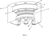
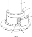
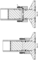
- a down-the-hole hammer 1 according to a second embodiment of the present invention is illustrated in Figures 6 to 8 .
- the hammer 1 of the second embodiment is similar to that of the first embodiment, and like reference numerals are used to refer to like elements.
- the second embodiment differs from the first embodiment in that the drive ring 11 comprises a plurality of part annular segments 46, as shown in Figures 7 and 8 .
- Each segment 46 is provided with three protrusions 16. In other embodiments, each segment may be provided with a greater or lesser number of protrusions.
- each segment 46 is formed with a shoulder 47, so that when the drive ring 11 is assembled, a continuous bit retaining shoulder 48 engages with the bit retaining shoulder 8 on the percussion bit to retain the bit in the hammer.
- the bit retaining ring 21 of the embodiment shown in Figures 1 to 5 may be provided as two part-annular bit retaining portions or halves 21a, 21b. In alternate embodiments, the ring 21 may be split into a greater number of portions.
- the depth D of the holes 25 in the collar 22 of the drive ring 11 is greater than a height H of the bit retaining ring. This allows the percussion bit 6 to be removed from the hammer without removing the drive ring 11. This may be achieved by withdrawing the bolts 30 from the holes 25 by a distance greater than or equal to the height H of the bit retaining ring portions but less than the depth D of the holes.
- the outer wear sleeve 2 can then be moved away from the percussion bit 6, for example by lifting the hammer, thereby creating an annular space 47 between the forward end 9 of the wear sleeve and the internal shoulder 24 of the drive ring.
- the bolts 30 are still engaged in the holes 25 and so the drive ring 11 is still retained in the hammer.
- a new bit may be inserted and the bit retaining ring halves 21a, 21b returned to the bit retaining position by way of pins 48, shown in Figure 11 , extending through the drive ring 11 and arranged to engage the halves 21a, 21b.
- a resilient o-ring may be provided around the bit retaining ring halves 21a, 21b to bias the halves inwardly such that they return to their original bit retaining position when the bit is removed.
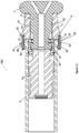
- the hammer 1201 comprises an outer wear sleeve 2 and a percussion bit 6 having a head portion 7 and a bit retaining shoulder 8 located at a forward end 9 of the outer wear sleeve.
- the hammer 1201 also comprises a sliding piston 10 mounted for reciprocating movement within the outer wear sleeve to strike the percussion bit.
- the hammer further comprises a drive ring 11 which has an annular collar 22 provided at a rear end 23 thereof, arranged to receive the forward end 9 of the wear sleeve such that the forward end of the wear sleeve abuts an internal shoulder 24 of the drive ring.
- a plurality of internally screw-threaded holes 25 are provided in a rear end 26 of the collar, and the rear end of the collar is arranged to abut a forward end 27 of a flange 18.
- a plurality of through holes 28 are provided in the flange. Each through hole corresponds to one of the plurality of holes in the collar.
- a bolt 30 is inserted into each through hole 28 and screwed into the corresponding hole 25 in the collar to connect the drive ring to the wear sleeve and thus to the drive means of the percussion drill tool.
- the clamping effect of this bolted arrangement also holds the bit retaining ring 21 in place between the drive ring 11 and an aligner 29.
- Splines 50 on the drive ring engage with complementary splines 51 on the percussion bit to transfer rotational drive to the bit.
- the bit retaining ring 21 is provided as two part-annular bit retaining ring halves 21a, 21b.
- the ring may comprise a larger number of part-annular portions.
- the depth D of the holes 25 in the collar 22 of the drive ring is greater than a height H of the bit retaining portions such that the percussion bit is removable from the drill tool by withdrawing the bolts 30 from the holes 25 by a distance greater than or equal to the height of the bit retaining portions 21a, 21b but less than the depth of the holes such that when the outer wear sleeve 2 is moved away from the percussion bit 6, an annular space is formed between the forward end of the wear sleeve and the internal shoulder of the drive ring, into which the bit retaining portions are moveable in a radially outward direction such that they no longer retain the percussion bit in the drill tool.
- the percussion bit 6 can thus be removed from the hammer 1201 without removing the drive ring 11, in a similar fashion to that described
Landscapes
- Engineering & Computer Science (AREA)
- Geology (AREA)
- Life Sciences & Earth Sciences (AREA)
- Mining & Mineral Resources (AREA)
- Mechanical Engineering (AREA)
- Physics & Mathematics (AREA)
- Environmental & Geological Engineering (AREA)
- Fluid Mechanics (AREA)
- General Life Sciences & Earth Sciences (AREA)
- Geochemistry & Mineralogy (AREA)
- Earth Drilling (AREA)
- Percussive Tools And Related Accessories (AREA)
- Drilling And Boring (AREA)
- Circuit For Audible Band Transducer (AREA)
Claims (7)
- Outil de forage à percussion actionné par fluide (1) comprenant :un manchon d'usure externe (2) comprenant une paroi sensiblement cylindrique (3) et ayant des surfaces intérieure (4) et extérieure (5) ;un trépan à percussion (6) ayant une partie de tête (7) et une partie de retenue de trépan (8) et situé à une extrémité avant (9) du manchon d'usure externe ;un piston coulissant (10) monté pour un mouvement alternatif à l'intérieur du manchon d'usure externe pour frapper le trépan à percussion ;une bague d'entraînement (11) ayant une paroi sensiblement cylindrique (12) et comprenant des moyens de connexion (13) adaptés pour connecter la bague d'entraînement à un moyen d'entraînement de l'outil de forage à percussion actionné par fluide ; etcaractérisé par une bride annulaire (18) disposée autour du manchon d'usure externe à l'extrémité avant de celui-ci, la bride comprenant une pluralité de trous traversants (28) ménagés dans celle-ci et étant empêchée de se déplacer vers l'avant par rapport au manchon d'usure par l'engagement d'un épaulement interne (19) prévu sur la bride avec un épaulement externe (20) prévu à l'extrémité avant du manchon d'usure ; etdans lequel les moyens de connexion de la bague d'entraînement comprennent un collier annulaire (22) prévu à une extrémité arrière de la bague d'entraînement, le collier comprenant une pluralité de trous (25) prévus dans une extrémité arrière (26) de celle-ci, dans lequel chaque trou correspond à l'un de la pluralité de trous traversants dans la bride, le collier étant agencé pour recevoir l'extrémité avant du manchon d'usure de telle sorte que l'extrémité avant du manchon d'usure vienne en butée contre un épaulement interne (24) de la bague d'entraînement et l'extrémité arrière du collier soit agencée pour venir en butée contre une extrémité avant (27) de la bride et dans lequel chaque trou traversant et trou correspondant dans le collier sont configurés pour recevoir un élément de fixation (30) pour connecter la bague d'entraînement aux moyens d'entraînement de l'outil de forage à percussion.
- Outil de forage à percussion actionné par fluide selon la revendication 1, comprenant en outre une bague de retenue de trépan (21) agencée pour venir en prise avec la partie de retenue de trépan du trépan pour forage à percussion pour retenir le trépan pour forage à percussion dans l'outil de forage, dans lequel la bague de retenue de trépan est serrée entre la bague d'entraînement et un aligneur (29) par la prise des éléments de fixation avec la bague d'entraînement.
- Outil de forage à percussion actionné par fluide selon la revendication 2, dans lequel la bague de retenue de trépan est prévue sous la forme d'une pluralité de parties de retenue de trépan partiellement annulaires (21a, 21b) ; et
dans lequel la profondeur des trous dans le collier de la bague d'entraînement est supérieure à une hauteur des parties de retenue de trépan de sorte que le trépan pour forage à percussion peut être retiré de l'outil de forage en retirant les éléments de fixation des trous sur une distance supérieure ou égale à la hauteur des parties de retenue de trépan mais inférieure à la profondeur des trous de sorte que lorsque le manchon d'usure extérieur est éloigné du trépan pour forage à percussion, un espace annulaire (47) est formé entre l'extrémité avant du manchon d'usure et l'épaulement interne de la bague d'entraînement, dans lequel les parties de retenue de trépan peuvent se déplacer dans une direction radiale vers l'extérieur de sorte qu'elles ne retiennent plus le trépan pour forage à percussion dans l'outil de forage. - Outil de forage à percussion actionné par fluide selon la revendication 3, comprenant en outre un joint torique disposé autour des parties de retenue de trépan.
- Outil de forage à percussion actionné par fluide selon la revendication 3, comprenant en outre une pluralité de broches (48) s'étendant à travers la bague d'entraînement et agencées pour venir en prise avec les parties de retenue du trépan.
- Procédé de retrait d'un trépan pour forage à percussion d'un outil de forage à percussion actionné par fluide selon la revendication 3, comprenant les étapes consistant à :retirer les éléments de fixation des trous sur une distance supérieure ou égale à la hauteur des parties de retenue du trépan mais inférieure à la profondeur des trous ;éloigner le manchon d'usure extérieur et la bague d'entraînement l'un de l'autre pour créer un espace annulaire entre l'extrémité avant du manchon d'usure et l'épaulement interne de la bague d'entraînement ; etéloigner l'outil de forage et le trépan pour forage à percussion l'un de l'autre, de telle sorte que la partie de retenue du trépan pour forage à percussion amène les parties de retenue du trépan de la bague de retenue du trépan à se déplacer dans une direction radiale vers l'extérieur dans l'espace annulaire.
- Procédé selon la revendication 6, dans lequel le procédé consiste en outre à remplacer le trépan à percussion, le procédé comprenant en outre :l'insertion d'un trépan à percussion dans l'extrémité distale de l'outil de forage à percussion ;le déplacement des parties de retenue de trépan de la bague de retenue de trépan dans une direction radiale vers l'intérieur en actionnant une pluralité de broches s'étendant à travers la bague d'entraînement et agencées pour s'engager dans les parties de retenue de trépan ; etle déplacement du manchon d'usure externe vers le trépan à percussion et la réinsertion des éléments de fixation dans les trous.
Applications Claiming Priority (4)
| Application Number | Priority Date | Filing Date | Title |
|---|---|---|---|
| IES20200053 | 2020-03-30 | ||
| IES20200239 | 2020-10-28 | ||
| PCT/EP2021/057827 WO2021198038A1 (fr) | 2020-03-30 | 2021-03-25 | Agencements de rinçage et de raccordement pour outils de forage à percussion |
| EP21712395.9A EP4127375B1 (fr) | 2020-03-30 | 2021-03-25 | Agencements de rinçage et de raccordement pour outils de forage à percussion |
Related Parent Applications (2)
| Application Number | Title | Priority Date | Filing Date |
|---|---|---|---|
| EP21712395.9A Division-Into EP4127375B1 (fr) | 2020-03-30 | 2021-03-25 | Agencements de rinçage et de raccordement pour outils de forage à percussion |
| EP21712395.9A Division EP4127375B1 (fr) | 2020-03-30 | 2021-03-25 | Agencements de rinçage et de raccordement pour outils de forage à percussion |
Publications (4)
| Publication Number | Publication Date |
|---|---|
| EP4339416A2 EP4339416A2 (fr) | 2024-03-20 |
| EP4339416A3 EP4339416A3 (fr) | 2024-05-29 |
| EP4339416B1 true EP4339416B1 (fr) | 2025-05-14 |
| EP4339416C0 EP4339416C0 (fr) | 2025-05-14 |
Family
ID=75339743
Family Applications (2)
| Application Number | Title | Priority Date | Filing Date |
|---|---|---|---|
| EP21712395.9A Active EP4127375B1 (fr) | 2020-03-30 | 2021-03-25 | Agencements de rinçage et de raccordement pour outils de forage à percussion |
| EP24155400.5A Active EP4339416B1 (fr) | 2020-03-30 | 2021-03-25 | Agencements de rinçage et de raccordement pour outils de forage à percussion |
Family Applications Before (1)
| Application Number | Title | Priority Date | Filing Date |
|---|---|---|---|
| EP21712395.9A Active EP4127375B1 (fr) | 2020-03-30 | 2021-03-25 | Agencements de rinçage et de raccordement pour outils de forage à percussion |
Country Status (11)
| Country | Link |
|---|---|
| US (1) | US12024950B2 (fr) |
| EP (2) | EP4127375B1 (fr) |
| JP (1) | JP7728791B2 (fr) |
| KR (1) | KR20220156621A (fr) |
| CN (1) | CN115362307A (fr) |
| AU (1) | AU2021246814A1 (fr) |
| BR (1) | BR112022019702A2 (fr) |
| CA (1) | CA3177060A1 (fr) |
| CL (2) | CL2022002626A1 (fr) |
| WO (1) | WO2021198038A1 (fr) |
| ZA (1) | ZA202211084B (fr) |
Family Cites Families (20)
| Publication number | Priority date | Publication date | Assignee | Title |
|---|---|---|---|---|
| US2461530A (en) | 1943-07-02 | 1949-02-15 | Joy Mfg Co | Rock drill |
| US3387671A (en) * | 1965-10-15 | 1968-06-11 | Mission Mfg Co | Percussion tool |
| US3981540A (en) * | 1973-10-23 | 1976-09-21 | Creare, Incorporated | Rock breaking apparatus |
| GB8611091D0 (en) * | 1986-05-07 | 1986-06-11 | Ennis M S J | Borehole drill construction |
| US4819746A (en) * | 1987-01-13 | 1989-04-11 | Minroc Technical Promotions Ltd. | Reverse circulation down-the-hole hammer drill and bit therefor |
| AU608441B2 (en) * | 1988-06-15 | 1991-03-28 | Abraham Gien | Down the hole hammer equipment |
| AUPQ302599A0 (en) * | 1999-09-22 | 1999-10-21 | Azuko Pty Ltd | Drilling apparatus |
| ZA200606939B (en) | 2005-08-25 | 2007-11-28 | Gien Bernard L | A dril bit |
| EP2313602A4 (fr) * | 2008-06-03 | 2015-11-11 | Atlas Copco Rock Drills Ab | Dispositif et procédé comprenant une tête de rinçage pour une perforatrice, et perforatrice comprenant le dispositif |
| SE533590C2 (sv) * | 2009-01-14 | 2010-11-02 | Wassara Ab | Borrkrona för sänkborrmaskin |
| US8544566B2 (en) * | 2010-06-15 | 2013-10-01 | Eastern Drillers Manufacturing, Inc. | Fluid actuated impact tool with solid piston-standard bit arrangement and water seal |
| CA2810914A1 (fr) * | 2010-09-10 | 2012-03-15 | Rockdrill Services Australia Pty Ltd | Fleuret de mine ameliore |
| WO2014185855A2 (fr) * | 2013-05-17 | 2014-11-20 | Atlas Copco Secoroc Ab | Dispositif et système permettant un forage de roches par percussion |
| CN103953279B (zh) * | 2014-04-30 | 2016-02-17 | 西南石油大学 | 一种往复冲击潜孔锤钻井工具 |
| WO2017013597A1 (fr) * | 2015-07-20 | 2017-01-26 | Gien Bernard L | Marteau de forage pneumatique |
| CA3123107A1 (fr) * | 2016-12-14 | 2018-06-21 | Jaime Andres Aros | Systeme d'ecoulement de fluide sous pression comprenant plusieurs chambres de travail pour un marteau de fond de trou et marteau de fond de trou a circulation normale comprenant l edit systeme |
| IES20180049A2 (en) | 2017-07-20 | 2018-11-14 | Mincon Int Ltd | Drill bit with detachable bit head |
| WO2019092600A1 (fr) | 2017-11-07 | 2019-05-16 | Gien Bernard L | Marteau perforateur pneumatique |
| IES20180460A2 (en) | 2018-11-22 | 2019-08-21 | Mincon Int Ltd | Drill bit assembly for percussion drill tools |
| CN109296311A (zh) | 2018-12-03 | 2019-02-01 | 长沙超金刚机械制造有限公司 | 一种高压气体潜孔冲击器 |
-
2021
- 2021-03-25 JP JP2022559643A patent/JP7728791B2/ja active Active
- 2021-03-25 US US17/914,945 patent/US12024950B2/en active Active
- 2021-03-25 EP EP21712395.9A patent/EP4127375B1/fr active Active
- 2021-03-25 CA CA3177060A patent/CA3177060A1/fr active Pending
- 2021-03-25 AU AU2021246814A patent/AU2021246814A1/en active Pending
- 2021-03-25 WO PCT/EP2021/057827 patent/WO2021198038A1/fr not_active Ceased
- 2021-03-25 BR BR112022019702A patent/BR112022019702A2/pt unknown
- 2021-03-25 KR KR1020227037143A patent/KR20220156621A/ko active Pending
- 2021-03-25 EP EP24155400.5A patent/EP4339416B1/fr active Active
- 2021-03-25 CN CN202180026255.3A patent/CN115362307A/zh active Pending
-
2022
- 2022-09-27 CL CL2022002626A patent/CL2022002626A1/es unknown
- 2022-10-10 ZA ZA2022/11084A patent/ZA202211084B/en unknown
-
2024
- 2024-02-19 CL CL2024000500A patent/CL2024000500A1/es unknown
Also Published As
| Publication number | Publication date |
|---|---|
| US20230151694A1 (en) | 2023-05-18 |
| BR112022019702A2 (pt) | 2022-11-22 |
| EP4127375B1 (fr) | 2024-03-20 |
| ZA202211084B (en) | 2024-02-28 |
| CL2022002626A1 (es) | 2023-06-02 |
| EP4127375C0 (fr) | 2024-03-20 |
| CA3177060A1 (fr) | 2021-10-07 |
| EP4339416C0 (fr) | 2025-05-14 |
| EP4127375A1 (fr) | 2023-02-08 |
| EP4339416A2 (fr) | 2024-03-20 |
| EP4339416A3 (fr) | 2024-05-29 |
| US12024950B2 (en) | 2024-07-02 |
| CN115362307A (zh) | 2022-11-18 |
| AU2021246814A1 (en) | 2022-11-10 |
| KR20220156621A (ko) | 2022-11-25 |
| JP2023520422A (ja) | 2023-05-17 |
| JP7728791B2 (ja) | 2025-08-25 |
| WO2021198038A1 (fr) | 2021-10-07 |
| CL2024000500A1 (es) | 2024-09-06 |
Similar Documents
| Publication | Publication Date | Title |
|---|---|---|
| EP1910640B1 (fr) | Ensemble de trépan pour des outils de forage à percussion à commande hydraulique | |
| US9103165B2 (en) | Down-the-hole hammer | |
| EP3655614B1 (fr) | Foret à tête détachable | |
| CN113631793A (zh) | 用于冲击钻凿的岩钻头 | |
| US12196059B2 (en) | Spline lubrication for DTH hammers | |
| EP4339416B1 (fr) | Agencements de rinçage et de raccordement pour outils de forage à percussion | |
| HK40101389B (en) | Flushing and connection arrangements for percussion drill tools | |
| HK40101389A (en) | Flushing and connection arrangements for percussion drill tools | |
| HK40078595A (en) | Flushing and connection arrangements for percussion drill tools | |
| HK40078595B (en) | Flushing and connection arrangements for percussion drill tools | |
| IES87273Y1 (en) | Flushing and connection arrangements for percussion drill tools | |
| EP3884135B1 (fr) | Ensemble trépan pour outils de forage à percussion | |
| AU2018205207B2 (en) | Down-hole Hammer Drilling Tool with Interchangeable Drill Head | |
| HK40018049A (en) | Drill bit with detachable bit head | |
| HK40018049B (en) | Drill bit with detachable bit head |
Legal Events
| Date | Code | Title | Description |
|---|---|---|---|
| PUAI | Public reference made under article 153(3) epc to a published international application that has entered the european phase |
Free format text: ORIGINAL CODE: 0009012 |
|
| STAA | Information on the status of an ep patent application or granted ep patent |
Free format text: STATUS: THE APPLICATION HAS BEEN PUBLISHED |
|
| AC | Divisional application: reference to earlier application |
Ref document number: 4127375 Country of ref document: EP Kind code of ref document: P |
|
| AK | Designated contracting states |
Kind code of ref document: A2 Designated state(s): AL AT BE BG CH CY CZ DE DK EE ES FI FR GB GR HR HU IE IS IT LI LT LU LV MC MK MT NL NO PL PT RO RS SE SI SK SM TR |
|
| PUAL | Search report despatched |
Free format text: ORIGINAL CODE: 0009013 |
|
| REG | Reference to a national code |
Ref country code: HK Ref legal event code: DE Ref document number: 40101389 Country of ref document: HK |
|
| AK | Designated contracting states |
Kind code of ref document: A3 Designated state(s): AL AT BE BG CH CY CZ DE DK EE ES FI FR GB GR HR HU IE IS IT LI LT LU LV MC MK MT NL NO PL PT RO RS SE SI SK SM TR |
|
| RIC1 | Information provided on ipc code assigned before grant |
Ipc: E21B 10/36 20060101ALI20240422BHEP Ipc: E21B 4/14 20060101ALI20240422BHEP Ipc: E21B 1/38 20060101ALI20240422BHEP Ipc: E21B 1/30 20060101AFI20240422BHEP |
|
| STAA | Information on the status of an ep patent application or granted ep patent |
Free format text: STATUS: REQUEST FOR EXAMINATION WAS MADE |
|
| 17P | Request for examination filed |
Effective date: 20241114 |
|
| RBV | Designated contracting states (corrected) |
Designated state(s): AL AT BE BG CH CY CZ DE DK EE ES FI FR GB GR HR HU IE IS IT LI LT LU LV MC MK MT NL NO PL PT RO RS SE SI SK SM TR |
|
| GRAP | Despatch of communication of intention to grant a patent |
Free format text: ORIGINAL CODE: EPIDOSNIGR1 |
|
| STAA | Information on the status of an ep patent application or granted ep patent |
Free format text: STATUS: GRANT OF PATENT IS INTENDED |
|
| INTG | Intention to grant announced |
Effective date: 20250121 |
|
| GRAS | Grant fee paid |
Free format text: ORIGINAL CODE: EPIDOSNIGR3 |
|
| GRAA | (expected) grant |
Free format text: ORIGINAL CODE: 0009210 |
|
| STAA | Information on the status of an ep patent application or granted ep patent |
Free format text: STATUS: THE PATENT HAS BEEN GRANTED |
|
| AC | Divisional application: reference to earlier application |
Ref document number: 4127375 Country of ref document: EP Kind code of ref document: P |
|
| AK | Designated contracting states |
Kind code of ref document: B1 Designated state(s): AL AT BE BG CH CY CZ DE DK EE ES FI FR GB GR HR HU IE IS IT LI LT LU LV MC MK MT NL NO PL PT RO RS SE SI SK SM TR |
|
| REG | Reference to a national code |
Ref country code: GB Ref legal event code: FG4D |
|
| REG | Reference to a national code |
Ref country code: CH Ref legal event code: EP |
|
| REG | Reference to a national code |
Ref country code: IE Ref legal event code: FG4D |
|
| U01 | Request for unitary effect filed |
Effective date: 20250514 |
|
| U07 | Unitary effect registered |
Designated state(s): AT BE BG DE DK EE FI FR IT LT LU LV MT NL PT RO SE SI Effective date: 20250520 |
|
| PG25 | Lapsed in a contracting state [announced via postgrant information from national office to epo] |
Ref country code: ES Free format text: LAPSE BECAUSE OF FAILURE TO SUBMIT A TRANSLATION OF THE DESCRIPTION OR TO PAY THE FEE WITHIN THE PRESCRIBED TIME-LIMIT Effective date: 20250514 |
|
| PG25 | Lapsed in a contracting state [announced via postgrant information from national office to epo] |
Ref country code: GR Free format text: LAPSE BECAUSE OF FAILURE TO SUBMIT A TRANSLATION OF THE DESCRIPTION OR TO PAY THE FEE WITHIN THE PRESCRIBED TIME-LIMIT Effective date: 20250815 Ref country code: NO Free format text: LAPSE BECAUSE OF FAILURE TO SUBMIT A TRANSLATION OF THE DESCRIPTION OR TO PAY THE FEE WITHIN THE PRESCRIBED TIME-LIMIT Effective date: 20250814 |
|
| PG25 | Lapsed in a contracting state [announced via postgrant information from national office to epo] |
Ref country code: PL Free format text: LAPSE BECAUSE OF FAILURE TO SUBMIT A TRANSLATION OF THE DESCRIPTION OR TO PAY THE FEE WITHIN THE PRESCRIBED TIME-LIMIT Effective date: 20250514 |
|
| PG25 | Lapsed in a contracting state [announced via postgrant information from national office to epo] |
Ref country code: HR Free format text: LAPSE BECAUSE OF FAILURE TO SUBMIT A TRANSLATION OF THE DESCRIPTION OR TO PAY THE FEE WITHIN THE PRESCRIBED TIME-LIMIT Effective date: 20250514 |
|
| PG25 | Lapsed in a contracting state [announced via postgrant information from national office to epo] |
Ref country code: RS Free format text: LAPSE BECAUSE OF FAILURE TO SUBMIT A TRANSLATION OF THE DESCRIPTION OR TO PAY THE FEE WITHIN THE PRESCRIBED TIME-LIMIT Effective date: 20250814 |
|
| PG25 | Lapsed in a contracting state [announced via postgrant information from national office to epo] |
Ref country code: IS Free format text: LAPSE BECAUSE OF FAILURE TO SUBMIT A TRANSLATION OF THE DESCRIPTION OR TO PAY THE FEE WITHIN THE PRESCRIBED TIME-LIMIT Effective date: 20250914 |
|
| PG25 | Lapsed in a contracting state [announced via postgrant information from national office to epo] |
Ref country code: SM Free format text: LAPSE BECAUSE OF FAILURE TO SUBMIT A TRANSLATION OF THE DESCRIPTION OR TO PAY THE FEE WITHIN THE PRESCRIBED TIME-LIMIT Effective date: 20250514 |
|
| PG25 | Lapsed in a contracting state [announced via postgrant information from national office to epo] |
Ref country code: CZ Free format text: LAPSE BECAUSE OF FAILURE TO SUBMIT A TRANSLATION OF THE DESCRIPTION OR TO PAY THE FEE WITHIN THE PRESCRIBED TIME-LIMIT Effective date: 20250514 |
|
| PG25 | Lapsed in a contracting state [announced via postgrant information from national office to epo] |
Ref country code: SK Free format text: LAPSE BECAUSE OF FAILURE TO SUBMIT A TRANSLATION OF THE DESCRIPTION OR TO PAY THE FEE WITHIN THE PRESCRIBED TIME-LIMIT Effective date: 20250514 |
|
| PLBE | No opposition filed within time limit |
Free format text: ORIGINAL CODE: 0009261 |
|
| STAA | Information on the status of an ep patent application or granted ep patent |
Free format text: STATUS: NO OPPOSITION FILED WITHIN TIME LIMIT |
|
| REG | Reference to a national code |
Ref country code: CH Ref legal event code: L10 Free format text: ST27 STATUS EVENT CODE: U-0-0-L10-L00 (AS PROVIDED BY THE NATIONAL OFFICE) Effective date: 20260325 |
|
| U20 | Renewal fee for the european patent with unitary effect paid |
Year of fee payment: 6 Effective date: 20260304 |
|
| PGFP | Annual fee paid to national office [announced via postgrant information from national office to epo] |
Ref country code: GB Payment date: 20260304 Year of fee payment: 6 |
|
| PGFP | Annual fee paid to national office [announced via postgrant information from national office to epo] |
Ref country code: IE Payment date: 20260304 Year of fee payment: 6 |
|
| 26N | No opposition filed |
Effective date: 20260217 |