EP4339431A1 - Temperatureinstellungsvorrichtung - Google Patents
Temperatureinstellungsvorrichtung Download PDFInfo
- Publication number
- EP4339431A1 EP4339431A1 EP22807295.5A EP22807295A EP4339431A1 EP 4339431 A1 EP4339431 A1 EP 4339431A1 EP 22807295 A EP22807295 A EP 22807295A EP 4339431 A1 EP4339431 A1 EP 4339431A1
- Authority
- EP
- European Patent Office
- Prior art keywords
- sleeve
- groove
- temperature adjustment
- temperature
- distal
- Prior art date
- Legal status (The legal status is an assumption and is not a legal conclusion. Google has not performed a legal analysis and makes no representation as to the accuracy of the status listed.)
- Pending
Links
Images






Classifications
-
- F—MECHANICAL ENGINEERING; LIGHTING; HEATING; WEAPONS; BLASTING
- F01—MACHINES OR ENGINES IN GENERAL; ENGINE PLANTS IN GENERAL; STEAM ENGINES
- F01P—COOLING OF MACHINES OR ENGINES IN GENERAL; COOLING OF INTERNAL-COMBUSTION ENGINES
- F01P7/00—Controlling of coolant flow
- F01P7/14—Controlling of coolant flow the coolant being liquid
- F01P7/16—Controlling of coolant flow the coolant being liquid by thermostatic control
- F01P7/167—Controlling of coolant flow the coolant being liquid by thermostatic control by adjusting the pre-set temperature according to engine parameters, e.g. engine load, engine speed
-
- F—MECHANICAL ENGINEERING; LIGHTING; HEATING; WEAPONS; BLASTING
- F01—MACHINES OR ENGINES IN GENERAL; ENGINE PLANTS IN GENERAL; STEAM ENGINES
- F01P—COOLING OF MACHINES OR ENGINES IN GENERAL; COOLING OF INTERNAL-COMBUSTION ENGINES
- F01P7/00—Controlling of coolant flow
- F01P7/14—Controlling of coolant flow the coolant being liquid
- F01P7/16—Controlling of coolant flow the coolant being liquid by thermostatic control
-
- F—MECHANICAL ENGINEERING; LIGHTING; HEATING; WEAPONS; BLASTING
- F16—ENGINEERING ELEMENTS AND UNITS; GENERAL MEASURES FOR PRODUCING AND MAINTAINING EFFECTIVE FUNCTIONING OF MACHINES OR INSTALLATIONS; THERMAL INSULATION IN GENERAL
- F16K—VALVES; TAPS; COCKS; ACTUATING-FLOATS; DEVICES FOR VENTING OR AERATING
- F16K27/00—Construction of housing; Use of materials therefor
- F16K27/02—Construction of housing; Use of materials therefor of lift valves
-
- F—MECHANICAL ENGINEERING; LIGHTING; HEATING; WEAPONS; BLASTING
- F16—ENGINEERING ELEMENTS AND UNITS; GENERAL MEASURES FOR PRODUCING AND MAINTAINING EFFECTIVE FUNCTIONING OF MACHINES OR INSTALLATIONS; THERMAL INSULATION IN GENERAL
- F16K—VALVES; TAPS; COCKS; ACTUATING-FLOATS; DEVICES FOR VENTING OR AERATING
- F16K31/00—Actuating devices; Operating means; Releasing devices
- F16K31/002—Actuating devices; Operating means; Releasing devices actuated by temperature variation
-
- F—MECHANICAL ENGINEERING; LIGHTING; HEATING; WEAPONS; BLASTING
- F16—ENGINEERING ELEMENTS AND UNITS; GENERAL MEASURES FOR PRODUCING AND MAINTAINING EFFECTIVE FUNCTIONING OF MACHINES OR INSTALLATIONS; THERMAL INSULATION IN GENERAL
- F16K—VALVES; TAPS; COCKS; ACTUATING-FLOATS; DEVICES FOR VENTING OR AERATING
- F16K31/00—Actuating devices; Operating means; Releasing devices
- F16K31/02—Actuating devices; Operating means; Releasing devices electric; magnetic
- F16K31/025—Actuating devices; Operating means; Releasing devices electric; magnetic actuated by thermo-electric means
-
- G—PHYSICS
- G05—CONTROLLING; REGULATING
- G05D—SYSTEMS FOR CONTROLLING OR REGULATING NON-ELECTRIC VARIABLES
- G05D23/00—Control of temperature
- G05D23/01—Control of temperature without auxiliary power
- G05D23/02—Control of temperature without auxiliary power with sensing element expanding and contracting in response to changes of temperature
- G05D23/021—Control of temperature without auxiliary power with sensing element expanding and contracting in response to changes of temperature the sensing element being a non-metallic solid, e.g. elastomer, paste
- G05D23/022—Control of temperature without auxiliary power with sensing element expanding and contracting in response to changes of temperature the sensing element being a non-metallic solid, e.g. elastomer, paste the sensing element being placed within a regulating fluid flow
-
- F—MECHANICAL ENGINEERING; LIGHTING; HEATING; WEAPONS; BLASTING
- F01—MACHINES OR ENGINES IN GENERAL; ENGINE PLANTS IN GENERAL; STEAM ENGINES
- F01P—COOLING OF MACHINES OR ENGINES IN GENERAL; COOLING OF INTERNAL-COMBUSTION ENGINES
- F01P7/00—Controlling of coolant flow
- F01P7/14—Controlling of coolant flow the coolant being liquid
- F01P2007/146—Controlling of coolant flow the coolant being liquid using valves
Definitions
- This invention relates to a temperature adjustment device provided with a temperature adjustment member having a heating section or temperature sensing unit.
- thermostat device that controls the coolant temperature, disposed in a cooling circuit of an engine (an internal combustion engine), for example, is known as a temperature adjustment device.
- an accessory part such as a plug is attached using a clipping member, for example, to a sleeve provided on the housing of the thermostat device, as disclosed in patent literature 1.
- the accessory part is a temperature adjustment member such as a heater or a temperature sensor that requires energizing
- vibration causes wearing at electrical connections to have a contact failure (energizing failure) occur when rattling occurs in the temperature adjustment member.
- the temperature adjustment member needs to be firmly fixed to the housing without rattling.
- the temperature adjustment member is firmly fixed with a clip member to a housing made of synthetic resin, for example, there may be a risk of rattling in the temperature adjustment member due to creep deformation of the housing, and a contact failure occurs.
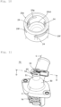
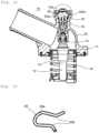
- a thermostat device 70 shown in Figs. 11 and 12 is provided with a heater 55 as a temperature adjustment member, and the heater 55 is fixed by a clip member 60 to a sleeve 51 of a housing 50.
- a groove 52 in a U-shape in plan view is formed opening sideward along the circumferential direction at the outer periphery of the sleeve 51, and step 51a is formed on the inner periphery of the sleeve 51.
- a lateral hole 53 penetrating from the inside of the groove 52 to the upper side in the figure of the step 51a is formed.
- a flange 51a1 protruding outward is formed on the attaching portion of a heater 55, and the flange 51a1 is configured to ride on the step 51a.
- the clip member 60 has an outer fitting portion 60a having a U-shape in plan view and inward convex portions 60b facing each other extending from both ends of the outer fitting portion.
- the clip member 60 presses the brim portion 55a1 of the heater 55 from the upper side in Fig. 15 , by fitting the outer fitting portion 60a into the groove 52 and inserting the inward convex portions 60b through the lateral hole 53 into the sleeve 51. Since the translation of the clip member 60 upward in the figure is stopped by the upper side wall in the figure of the groove 52, the heater 55 is prevented from coming off.
- the thermostat device 70 (temperature adjustment member) will be upsized.
- the present invention is made, focusing on the above points, and has an object to provide a temperature adjustment device that allows for suppressing the enlargement of the sleeve and inhibiting the occurrence of the rattling of the temperature adjustment member, even when the housing is made of synthetic resin.
- the temperature adjustment device includes a housing having a cylindrical sleeve, a temperature adjustment member having a heating section or temperature sensing unit which is inserted from the sleeve into the housing, and a clip member that fixes the temperature adjustment member to the sleeve, wherein a flange protruding outward is formed on the temperature adjustment member, the sleeve is provided with a groove formed on the outer periphery along the circumferential direction and a lateral hole whose one end is opened in the groove and that penetrates the thickness of the sleeve, the clip member includes an outer fitting portion elastically deformable and fittable to the groove and inward convex portions extending facing to each other from both ends of the outer fitting portion and pressing the flange from the distal-end side of the sleeve by being inserted through the lateral hole, the wall of the groove includes a groove-depth wall located at the deep-most portion of the groove opposite to the opening of the groove,
- the above constitution allows for inhibiting the sleeve from increasing in size due to the widened groove and inhibiting the temperature adjustment device from increasing in size. Further, since the above constitution allows to increase in the radius of curvature of the distal-end-side curved portion located at the distal end of the sleeve, inhibiting the deformation to be widened under the force from the clip member side and inhibiting the rattling of the temperature adjustment member can be achieved, even when the housing is made of synthetic resin.
- the outer fitting portion of the clip member may be made of wire material and the value of the radius of curvature of the distal-end-side curved portion may be equal to or less than the diameter of the wire material and more than a value of 1/2 of the wire diameter.
- the outer fitting portion of the clip member can be inserted deeply into the groove when the housing is made of a synthetic resin material that is deformable elastically and the stress generated at the distal-end-side curved portion can be reduced.
- the outer fitting portion may be made of wire material and the value of the radius of curvature of the distal-end-side curved portion may be equal to or less than a value of 1/2 of the wire diameter.
- ribs protruding inward radially may be provided at different positions in the circumferential direction at the inner periphery of the sleeve or the outer periphery of the temperature adjustment member, and the temperature adjustment member may be press-fitted into the sleeve.
- thermo-element driving the valve body to open and close by extension and retraction depending on the temperature of the coolant, and a biasing member that biases the valve body to the closing direction
- thermo-element includes a temperature-sensitive case incorporating a temperature-sensitive member whose volume changes depending on the temperature, a piston whose one end is supported by the housing and extends and retracts to the temperature-sensitive case depending on the volume change of the temperature-sensitive member, and the temperature adjustment member includes a heating section and the heating section may be inserted in the piston.
- the temperature adjustment device is the thermostat device provided with the thermo-element and the heating section of the temperature adjustment member is inserted in the piston
- the temperature adjustment member needs to be firmly fixed only by the clip member to the housing without rattling.
- the application of the present invention to the temperature adjustment device is particularly effective because the widening of the groove due to deformation is directly connected to the occurrence of the rattling of the temperature adjustment member.
- the temperature adjustment member may be a temperature sensor having a temperature sensing unit. In that case, the increase in the size of the sleeve is inhibited and the occurrence of the rattling of the temperature sensor is also inhibited, even when the housing to which the temperature sensor is attached is made of synthetic resin.
- the increase in the size of the sleeve is inhibited and the occurrence of the rattling of the temperature adjustment member is also inhibited, even when the housing is made of synthetic resin.
- the temperature adjustment device is a thermostat device that is provided in a cooling circuit of an engine (an internal combustion engine) and controls the temperature of the coolant.
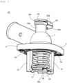
- Fig. 1 is a perspective view of a thermostat device as a temperature adjustment device according to a first embodiment
- Fig. 2 is a plan view of the thermostat device in Fig. 1
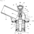
- Fig. 3 is an A-A cross-sectional view of the thermostat device in Fig. 2
- Fig. 4 is a partially enlarged cross-sectional view (a portion enclosed by a broken circle) of the thermostat device in Fig. 3
- Fig. 5 is a B-B cross-sectional view of the thermostat device in Fig. 2
- Fig. 6 is a partially enlarged cross-sectional view of the thermostat device in Fig. 5 .
- the thermostat device 10 is provided with a housing 1, a flow passage 4 of coolant formed in the housing 1, a valve body 15 that opens and closes the flow passage 4, a thermo-element 17 that drives to open and close the valve body 15 by extending and retracting depending on the coolant temperature, a coil spring 16 as a biasing member that biases the valve body 15 to the closing direction, a frame 19 that supports one end of the coil spring 16, a heater 40 as a temperature adjustment member, and a clip member 45 that fixes the heater 40 to the housing 1.
- the upper and lower portions of the thermostat device 10 shown in Fig. 3 are simply referred to as "the upper” and "the lower”.
- the housing 1 is made of synthetic resin.
- the housing 1 includes a body 20 having an approximately capped cylinder shape at the lower end of which an opening 20c, a pair of flanges 2, 2 outwardly protruding from the lower end outer periphery of the body 20, a pair of legs 21, 21 extending, facing to each other, downward from the lower opening edge of the body 20, a connecting port 23 of the radiator side extending obliquely upward from the top part of the body 20, and a sleeve 20e standing upward from the top part of the body 20, to which a heater is fixed.
- the coolant is to pass through the connecting port 23, inside of the body 20, and the opening 20c, which altogether constitute the flow passage 4 in the housing 1.
- bolt holes 2a are formed on each of the pair of flanges 2, 2.
- Metal tubes are press-fitted in the bolt holes 2a, and bolts (not shown) for fixing the thermostat device 10 to the counterpart member are inserted through the tube thereof.
- an annular groove 20d is formed so as to surround the opening 20c on the edge of the lower end opening of the body 20, which is located inside of the bolt holes 2a, and a gasket 25 is attached to the groove 20d.
- the gasket 25 seals between the thermostat device 10 and the counterpart member, and prevents the coolant flowing in the housing 1 from leaking outside in a state the thermostat device 10 is attached to the counterpart member.
- a region (space) inside (inner area of) the gasket 25 in the body 20 is denoted as the inside of the housing 1.
- the counterpart members denote, for example, a water pump, a water jacket of the engine, or a member for attaching the thermostat device thereto.
- An annular valve seat 20b is formed on the inner periphery just above the edge of the lower-end opening of the body 20 located inside the housing 1; the flow passage 4 is opened or closed by the valve body 15 unseated from or seated on the valve seat 20b.
- thermo-element 17 is inserted inside the housing 1.
- the thermo-element 17 is disposed at the axial center of the body 20 along the axis.
- the thermo-element 17 includes a temperature-sensitive case 30 incorporating a temperature-sensitive member such as wax whose volume changes depending on the temperature and a piston 3 whose upper end is supported by the housing 1 and exits and enters the temperature-sensitive case 30 depending on the volume change of the temperature-sensitive member.
- thermo-element 17 When the temperature of the coolant around the temperature-sensitive case 30 rises and the temperature-sensitive member expands, the piston goes out from the temperature-sensitive member 30 and the thermo-element 17 extends. In contrast, when the temperature of the coolant around the temperature-sensitive case 30 drops and the temperature-sensitive member inside contracts, the piston 3 enters the temperature-sensitive member 30 and the thermo-element 17 retracts. Thus, the thermo-element 17 operates to extend and retract depending on the temperature.
- thermo-element 17 The distal end of the piston 3 located at the upper end of the thermo-element 17 is fitted to a cylindrical boss portion 22a formed at the top portion inside the body 20; the movement of the piston 3 upward against the housing 1 is inhibited.
- the temperature-sensitive case 30 moves up and down by the operation of extension and retraction of the thermo-element 17 without changing the position of the piston 3 against the housing 1.
- the valve body 15 is fixed on the outer periphery of the temperature-sensitive case 30. This causes the valve body 15 to move up and down with the temperature-sensitive case 30 along with the extension and retraction of the thermo-element 17.
- the thermo-element extends and the valve body 15 moves downward, the valve body 15 is unseated from the valve seat 20b and the coolant can flow therebetween, the flow passage is allowed to be communicated.
- the thermo-element 17 contracts and the valve body 15 moves upward and is seated on the valve seat 20b, the communication of the flow passage 4 is closed.
- the valve 15 opens and closes the flow passage 4 by being unseated from or being seated on the valve seat 20b.
- the upper end of the coil spring 16 abuts the backside of the valve body 15.
- the coil spring is disposed so as to surround the thermo-element 17.
- the lower end (one end) of the coil spring 16 is supported by the frame 19.
- the frame 19 is hooked on the tip portion of the pair of the legs 21, 21 formed on the housing 1 and prevented from moving downward against the housing 1.
- a through-hole 19a is formed at the center of the frame 19.
- the temperature-sensitive case 30 is inserted movably vertically in the through-hole 19a. This means that the temperature-sensitive case 30 is movable vertically against the frame 19.
- the coil spring 16 is a compressive spring and is placed between the valve body 15 and the frame 19 in a compressed state.
- the valve body 15 is biased upward (toward the valve seat 20b side).
- the valve body 15 moves downward against the biasing force of the coil spring 16 and is unseated from the valve seat 20b. Meanwhile, when the coolant temperature around the thermo-element 17 is lowered and the thermo-element 17 retracts, the valve body 15 moves upward following the biasing force of the coil spring 16 and comes closer to the valve seat 20b.
- the valve body 15 can be actively operated to open and close by heating the temperature-sensitive member by energizing the heater 40.
- the heater 40 includes a heating section 40a in a bar-like shape that is inserted inside the piston 3, an attaching section 40b joined to one end of the heating section 40a and attached with a clip member to the sleeve 20e, and a connector 40d protruding sideward from the attaching section 40b.
- a cable for energizing is connected to the connector 40d and the connector 40 can be energized from a power source of the vehicle, for example.
- the heating section 40a When the heater 40 is energized, the heating section 40a generates heat, whereby the temperature sensitive portion in the temperature sensitive case 30 expands by the heating through the piston 3, and the piston is pushed out from the temperature sensitive case 30 to open the valve 15.
- a sleeve 20e disposed so as to stand up upward from the top of the body 20 on the axis of the body 20 of the housing 1.
- one end (a lower end) continuous to the body 20 is the proximal end of the sleeve 20e, and the opposite end (an upper end) to the proximal end is the distal end of the sleeve 20e.
- a groove 20f having an approximately U-shape in cross-section opening to the side direction (a direction perpendicular to the axis of the sleeve 20e) along the circumferential direction is formed on the outer periphery of the sleeve 20e.
- the inner diameter of the distal end of the sleeve 20e is greater than that right below.
- a step 20e1 is formed to face the distal end on the inner periphery of the sleeve 20e.
- a brim portion 40b1 projecting outward is formed at the attaching section 40b of the heater 40.
- the heater 40 is put into the sleeve 20e from the heating section 40a side, as shown in Fig. 7 , and as the attaching section 40b is inserted into the sleeve 20e, the entering of the heater 40 further into the housing 1 is blocked by abutting the brim portion 40b1 to the step 20e1.
- a seal member 46 such as an O-ring is mounted, thereby preventing water or dust outside the thermostat device 10 from incoming into the housing 1.
- the clip member 45 for fastening the heater 40 to the sleeve 20e is made of a metal material such as stainless steel and includes an elastically deformable outer fitting portion 45a having a U-shape or C-shape in plan view and inward convex portions 45b extending from both ends of the outer fitting portion 45a facing each other. Further, as described above, when the clip member 45 is fitted to the sleeve 20e in a state where the brim portion 41b1 of the heater 40 is abutted to the inner circumferential step 20e1 of the sleeve 20e as shown in Fig.
- the outer fitting portion 45a is fitted to the outer groove 20f of the sleeve 20e as shown in Fig. 6 and the inward convex portions 45b is inserted in the sleeve 20e through the lateral hole 20g to press the brim portion 40b1 from the upper side (the distal-end side of the sleeve 20e). With this, the heater 40 is prevented from coming off from the sleeve 20e and fixed to the sleeve 20e.
- an opening 20f6 of the groove 20f to which the outer fitting portion 45a of the clip member 45 is fitted is disposed to face outward at the side of the sleeve 20e, and the groove 20f opens sideward.
- the wall of the groove 20f is composed of a groove depth wall 20f1 which is located at the deep-most portion of the groove 20f at the opposite side of the opening 20f6 and a pair of opposing walls 20f4 and 20f5 extending from the distal-end side and the proximal-end side of the groove depth wall 20f1 toward the opening 20f6.
- the connecting portions of the opposing walls 20f4 and 20f5 connecting to the groove depth wall 20f1 are respectively curved to form a distal-end-side curved portion 20f2 and a proximal-end-side curved portion 20f3.
- the distance W between the portion where the clip member 45 abuts the opposing wall 20f4 at the distal end and the portion where the clip member 45 abuts the brim portion 40b1 is slightly narrower than the diameter D of the wire material of the clip member 45 (W ⁇ D). Because of this, an upward force is applied to the opposing wall 20f4 at the distal end from the clip member side 45 and a downward force is applied to the brim portion 41b1 from the clip member side 45, and the clip member 45 is pressed to the step 20e1. Thus the heater 40 is fixed to the sleeve 20e without rattling.
- the radius of curvature of the distal-end-side curved portion 20f2, the curved portion of the opposing wall 20f4 at the distal end is different from that of the proximal-end-side curved portion 20f3, the curved portion of the opposing wall 20f5 at the proximal end.
- the radius of curvature R1 of the distal-end-side curved portion 20f2 is greater than the radius of curvature R2 of the proximal-end-side curved portion 20f3 (R1>R2).
- the stress is preferably reduced by increasing the radius of curvature of the curved portion that is continuous to the groove depth wall 20f1.
- the increase in both radii of curvature R1 and R2 of the distal-end-side curved portion 20f2 and the proximal-end-side curved portion 20f3, which are continuous to the groove depth wall 20f1, may widen the vertical width of the groove 20f and hinder the use of assembly equipment similar to the conventional one or increase the thermostat device in size due to the increase of the sleeve 20e.
- the stress is satisfactorily reduced by increasing the radius of curvature R1 of the distal-end-side curved portion 20f2, which is the curved portion of the opposing wall 20f4 located at the distal end side of the sleeve 20e that receives upward force from the clip member 45 side. Resultantly, even if the housing 1 is made of synthetic resin, the groove 20f can be inhibited from being deformed to be widened under the force from the clip member 45 side, and the rattling of the heater 40 (temperature adjustment member) can be suppressed.
- the outer fitting portion 45a of the clip member 45 is made of wire material in the thermostat device 10 of the first embodiment.
- the radius of curvature R1 of the distal-end-side curved portion 20f2 is less than or equal to the wire diameter D and greater than 1/2 of the wire diameter D (1/2D ⁇ R1 ⁇ D).
- the radius of curvature R1 of the distal-end-side curved portion 20f2 is preferably increased. If the radius of curvature R1 of the distal-end-side curved portion 20f2 is increased without changing the vertical width of the groove 20f, the fitting portion 45a of the clip member 45 is hard to insert deeply in the groove 20f. Further, when the outer fitting portion 45a of the clip member 45 cannot be inserted deeply in the groove 20f, the clip member 45 becomes apt to come off by vibration and further disadvantageous to deformation due to the increase of the moment.
- the clip member 45 can be easily inserted into the groove 20f deeply while elastically deforming the housing 1, and the stress occurring at the distal-end side curved portion 20f2 can be reduced.
- the clip member 45 can be easily inserted into the groove 20f deeply, by setting the radius of curvature of the distal-end-side curved portion 20f2 less than or equal to 1/2 of the diameter D of the wire material (R1 ⁇ (1/2)D).
- the temperature adjustment device is the thermostat device 10; the thermostat device 10 is provided with the flow passage 4 of the coolant formed in the housing 1, the valve body 15 that opens and closes the flow passage 4, the thermo-element 17 that operates to open or close the valve body 15 by the advancing and retracting depending on the coolant temperature, and the coil spring 17 (biasing member) biasing the valve body 15 to the valve-closed direction.
- thermo-element 17 includes the temperature-sensitive case 30 incorporating a temperature-sensitive body whose volume changes in response to the temperature, the piston 3 whose one end is supported by the housing 1 and exits and enters the temperature-sensitive case 30 in response to the temperature.
- the temperature-adjusting device is the heater 40 which has the heating section 40a and the heating section 40a is inserted in the piston 3.
- the temperature-adjusting member is the heater 40 having the heating section 40a, and the heating section 40a is inserted into the piston 1, the heater 40 needs to be firmly fixed to the housing 1 without rattling only by the clip member 45. It is because, for example, in the case where the temperature-adjusting member is a temperature sensor having a temperature sensing unit and the temperature sensing unit is disposed in the flow passage of the coolant, the temperature-adjusting member is biased to the exit direction under pressure in the flow passage and rattling might be reduced.
- the heating section 40a is a heater 40 inserted into the piston 3
- the heater is not biased by the pressure in the piston 1; the deformation of the groove 20f to be widened is directly connected to the occurrence of the rattling of the heater 40 (temperature-adjusting member). Because of the above reason, the application of the present invention to the thermostat device 10 having the above configuration is particularly effective.
- the thermostat device 10 of the second embodiment differs from the first embodiment in that the temperature adjustment member is a temperature sensor 41 equipped with a temperature sensing unit 41a; the basic structure of the thermostat device is the same as in the first embodiment.
- the same parts and portions that are identical or correspond to those in the first embodiment, and the same reference signs are used to omit detailed explanations.
- the sleeve 20e is provided on the side of the body 20 of the housing 1, and the temperature sensor 41 is fixed to the sleeve 20e with a clip member 45.
- the temperature sensor 41 is provided with a bar-like temperature sensing unit 41a inserted in the flow passage 4, an attaching portion 41b equipped on one end of the temperature sensing unit 41a, and a connector (not shown) extending sideward from the fixing portion 41b.
- the attaching portion 41b is provided with a brim portion, similar to the attaching section 40b of the first embodiment, and the temperature sensor 41 is fixed to the sleeve 20e similar to the heater 40 of the first embodiment.
- the temperature adjustment member may be a temperature sensor 41.
- the sleeve 20b and the temperature adjustment member of the present invention may not be necessarily utilized in the thermostat device.
- the sleeve 20e of the present invention may be attached to a conduit through which liquid or gas passes, and the temperature adjustment member may be fixed with the clip member 45.
- multiple ribs 24 may be provided at different positions on the circumferential surface in the circumferential direction of the sleeve 20e, and the temperature adjustment members such as the heater 40 or temperature sensor 41 may be press-fitted to the sleeve 20e.
- the motion of the temperature adjustment member by an external force such as vibration can be inhibited, and the occurrence of rattling of the temperature adjustment member can be inhibited more reliably.
- the electrical connections are more reliably prevented from wearing out and causing contact failures.
- the temperature adjustment member is prevented from being moved by the clip member 45 in the direction of attachment (arrow direction in Fig. 8 ) and from being fixed at a position radially displaced from the center of the sleeve 20e.
- the temperature adjustment member is decentered radially from the center of the sleeve 20e in that way, the sealing member 46 is compressed unevenly and the sealability of the sealing member 46 deteriorates (the compression increases at a portion of the circumferential direction of the sealing member 46 and the compression decreases at the opposite side.) For this reason, the temperature adjustment member is press-fitted to ribs 24 formed on the inner circumferential surface of the sleeve 20e, thereby capable of preventing the decentering of the temperature adjustment member and the deterioration of the sealability of the sealing member 46.
- the temperature adjustment member is fixed in the radial direction and prevented from rotating in the circumferential direction in the sleeve 20e. This allows fixing the connector 40d in a certain direction, reducing the mounting space in the vehicles, and making it easy to connect to cables, for example.
- the rib 24 can be eliminated to press-fit the entire periphery of the temperature adjustment member.
- the ribs 24 shown in Fig. 10 are long in length (vertically long), are disposed so as to extend along the axial direction of the sleeve 20e, and project toward the center (inward radially) from the inner periphery of the sleeve 20e.
- the ribs 24 are provided on the inner periphery of the sleeve 20e in three equally spaced strips.
- the ribs 24 are provided along the direction of vibration; the direction of assembly of the temperature adjustment member is preferably aligned with the direction of vibration. If the depth of press-fitting is not deep enough, the number of ribs is preferably increased. The number of ribs 24 is preferably odd more than or equal to three to ensure the coaxial property, but appropriately changeable. The shape of the ribs 24 is not limited to a long-sized one and is appropriately changeable.
- the ribs 24 may be provided on the outer periphery of the temperature adjustment member, and even in that case, similar effects are available as in the case provided on the inner periphery of the sleeve 20e.
Landscapes
- Engineering & Computer Science (AREA)
- General Engineering & Computer Science (AREA)
- Mechanical Engineering (AREA)
- Physics & Mathematics (AREA)
- Fluid Mechanics (AREA)
- General Physics & Mathematics (AREA)
- Automation & Control Theory (AREA)
- Chemical & Material Sciences (AREA)
- Combustion & Propulsion (AREA)
- Temperature-Responsive Valves (AREA)
- Cookers (AREA)
Applications Claiming Priority (2)
| Application Number | Priority Date | Filing Date | Title |
|---|---|---|---|
| JP2021082649 | 2021-05-14 | ||
| PCT/JP2022/017598 WO2022239592A1 (ja) | 2021-05-14 | 2022-04-12 | 温調装置 |
Publications (2)
| Publication Number | Publication Date |
|---|---|
| EP4339431A1 true EP4339431A1 (de) | 2024-03-20 |
| EP4339431A4 EP4339431A4 (de) | 2025-04-23 |
Family
ID=84028246
Family Applications (1)
| Application Number | Title | Priority Date | Filing Date |
|---|---|---|---|
| EP22807295.5A Pending EP4339431A4 (de) | 2021-05-14 | 2022-04-12 | Temperatureinstellungsvorrichtung |
Country Status (6)
| Country | Link |
|---|---|
| US (1) | US12276990B2 (de) |
| EP (1) | EP4339431A4 (de) |
| JP (1) | JP7808101B2 (de) |
| CN (1) | CN117321294B (de) |
| CA (1) | CA3217743A1 (de) |
| WO (1) | WO2022239592A1 (de) |
Family Cites Families (23)
| Publication number | Priority date | Publication date | Assignee | Title |
|---|---|---|---|---|
| GB946275A (en) * | 1962-09-17 | 1964-01-08 | Sulzer Bros London Ltd | Flow regulating valves |
| US4349806A (en) * | 1980-11-03 | 1982-09-14 | Texas Instruments Incorporated | Snap-acting thermostatic switch using inflexible, spring biased contact arm |
| JPH09303354A (ja) * | 1996-05-21 | 1997-11-25 | Kioritz Corp | 抜け止め構造体、及び、該抜け止め構造体を備えた刈払機 |
| JP3677925B2 (ja) | 1997-02-26 | 2005-08-03 | 株式会社デンソー | 回転ケーブルの結合構造 |
| DE10032354B4 (de) * | 2000-07-04 | 2011-02-17 | Behr Thermot-Tronik Gmbh | Thermostatventil mit elektrisch beheizbarem Arbeitselement |
| JP4378671B2 (ja) | 2001-07-19 | 2009-12-09 | 日本精工株式会社 | トロイダル型無段変速機 |
| JP2003328753A (ja) * | 2002-05-10 | 2003-11-19 | Nippon Thermostat Co Ltd | 電子制御サーモスタット |
| JP4354794B2 (ja) | 2002-12-18 | 2009-10-28 | 株式会社パイオラックス | チェッカー付きコネクタ |
| JP4951160B2 (ja) | 2006-06-29 | 2012-06-13 | ボルグワーナー・モールステック・ジャパン株式会社 | テンショナ |
| CA2727578C (en) * | 2008-07-10 | 2016-02-09 | Nippon Thermostat Co., Ltd. | Thermostat device |
| JP5111292B2 (ja) | 2008-08-20 | 2013-01-09 | ダイハツ工業株式会社 | 自動車における液体排出装置 |
| JP2010084743A (ja) * | 2008-10-02 | 2010-04-15 | Fuji Seiko Kk | サーモスタット装置 |
| EP2347425B1 (de) | 2008-10-31 | 2015-01-14 | Robert Bosch GmbH | Elektromagnet |
| JP5288614B2 (ja) * | 2009-04-24 | 2013-09-11 | 日本サーモスタット株式会社 | サーモスタット装置 |
| JP2011117541A (ja) | 2009-12-04 | 2011-06-16 | Nissin Kogyo Co Ltd | 流体式アクチュエータの配管接続構造 |
| JP5039803B2 (ja) * | 2010-03-04 | 2012-10-03 | 日本サーモスタット株式会社 | 内燃機関の冷却装置 |
| US9217358B2 (en) * | 2010-07-27 | 2015-12-22 | Fuji Bellows Co., Ltd. | Thermostat device with formed seal |
| WO2012109372A1 (en) * | 2011-02-08 | 2012-08-16 | Caltherm Corporation | Dual-valve thermostat |
| JP5407000B1 (ja) * | 2013-04-11 | 2014-02-05 | 幸雄 大西 | サーモエレメント及びサーモスタット |
| DE102014219490A1 (de) | 2014-09-25 | 2016-03-31 | Behr Thermot-Tronik Gmbh | Thermostatventil |
| CN110630729B (zh) * | 2018-06-24 | 2021-02-09 | 浙江三花汽车零部件有限公司 | 调温阀 |
| CN110762247B (zh) * | 2018-07-26 | 2022-02-08 | 浙江三花汽车零部件有限公司 | 一种流体控制阀 |
| CN112096504B (zh) * | 2020-09-22 | 2022-04-19 | 宁波兴慈热动电器有限公司 | 一种节温器 |
-
2022
- 2022-04-12 EP EP22807295.5A patent/EP4339431A4/de active Pending
- 2022-04-12 CA CA3217743A patent/CA3217743A1/en active Pending
- 2022-04-12 WO PCT/JP2022/017598 patent/WO2022239592A1/ja not_active Ceased
- 2022-04-12 US US18/289,190 patent/US12276990B2/en active Active
- 2022-04-12 JP JP2023520930A patent/JP7808101B2/ja active Active
- 2022-04-12 CN CN202280034159.8A patent/CN117321294B/zh active Active
Also Published As
| Publication number | Publication date |
|---|---|
| CA3217743A1 (en) | 2022-11-17 |
| EP4339431A4 (de) | 2025-04-23 |
| JPWO2022239592A1 (de) | 2022-11-17 |
| JP7808101B2 (ja) | 2026-01-28 |
| WO2022239592A1 (ja) | 2022-11-17 |
| US20240219939A1 (en) | 2024-07-04 |
| CN117321294A (zh) | 2023-12-29 |
| US12276990B2 (en) | 2025-04-15 |
| CN117321294B (zh) | 2026-07-24 |
Similar Documents
| Publication | Publication Date | Title |
|---|---|---|
| US11608903B2 (en) | Valve device | |
| JP5288614B2 (ja) | サーモスタット装置 | |
| US9052030B2 (en) | Thermostat device | |
| CN1639801B (zh) | 热电偶 | |
| EP3048368B1 (de) | Ventil einer dynamischen ventildichtung mit befestigungseinrichtung | |
| CN103403413B (zh) | 密封装置 | |
| EP2487391A1 (de) | Dichtungsvorrichtung | |
| US12276990B2 (en) | Temperature adjustment device | |
| EP4610531A1 (de) | Temperatureinstellungsvorrichtung | |
| EP4286667B1 (de) | Thermostat | |
| US7987868B2 (en) | Decoupled housing seat | |
| EP4286721A1 (de) | Thermostatvorrichtung und verfahren zur herstellung einer thermostatvorrichtung | |
| US20250376975A1 (en) | Thermally Responsive Actuator | |
| US12404944B2 (en) | Cover member and thermostat device equipped with cover member | |
| JPH0673572U (ja) | ワックス・ペレット型サーモスタット用エレメント |
Legal Events
| Date | Code | Title | Description |
|---|---|---|---|
| STAA | Information on the status of an ep patent application or granted ep patent |
Free format text: STATUS: THE INTERNATIONAL PUBLICATION HAS BEEN MADE |
|
| PUAI | Public reference made under article 153(3) epc to a published international application that has entered the european phase |
Free format text: ORIGINAL CODE: 0009012 |
|
| STAA | Information on the status of an ep patent application or granted ep patent |
Free format text: STATUS: REQUEST FOR EXAMINATION WAS MADE |
|
| 17P | Request for examination filed |
Effective date: 20231124 |
|
| AK | Designated contracting states |
Kind code of ref document: A1 Designated state(s): AL AT BE BG CH CY CZ DE DK EE ES FI FR GB GR HR HU IE IS IT LI LT LU LV MC MK MT NL NO PL PT RO RS SE SI SK SM TR |
|
| DAV | Request for validation of the european patent (deleted) | ||
| DAX | Request for extension of the european patent (deleted) | ||
| A4 | Supplementary search report drawn up and despatched |
Effective date: 20250325 |
|
| RIC1 | Information provided on ipc code assigned before grant |
Ipc: G05D 23/02 20060101ALI20250319BHEP Ipc: F16K 31/00 20060101ALI20250319BHEP Ipc: F01P 7/16 20060101AFI20250319BHEP |