EP4339519A1 - Système constitué d'un meuble de cuisine, d'une plaque de cuisson et d'un hotte aspirante - Google Patents
Système constitué d'un meuble de cuisine, d'une plaque de cuisson et d'un hotte aspirante Download PDFInfo
- Publication number
- EP4339519A1 EP4339519A1 EP23196781.1A EP23196781A EP4339519A1 EP 4339519 A1 EP4339519 A1 EP 4339519A1 EP 23196781 A EP23196781 A EP 23196781A EP 4339519 A1 EP4339519 A1 EP 4339519A1
- Authority
- EP
- European Patent Office
- Prior art keywords
- kitchen furniture
- housing
- air flow
- panel
- extractor
- Prior art date
- Legal status (The legal status is an assumption and is not a legal conclusion. Google has not performed a legal analysis and makes no representation as to the accuracy of the status listed.)
- Pending
Links
- 238000010411 cooking Methods 0.000 title claims abstract description 13
- 239000003517 fume Substances 0.000 claims abstract description 12
- 235000019645 odor Nutrition 0.000 claims abstract description 7
- 230000005291 magnetic effect Effects 0.000 claims description 5
- 238000010276 construction Methods 0.000 abstract description 4
- 238000000605 extraction Methods 0.000 abstract description 3
- 239000004519 grease Substances 0.000 abstract 1
- OKTJSMMVPCPJKN-UHFFFAOYSA-N Carbon Chemical compound [C] OKTJSMMVPCPJKN-UHFFFAOYSA-N 0.000 description 2
- 230000001419 dependent effect Effects 0.000 description 1
- 238000011161 development Methods 0.000 description 1
- 230000018109 developmental process Effects 0.000 description 1
- 230000005294 ferromagnetic effect Effects 0.000 description 1
- 238000009434 installation Methods 0.000 description 1
- 230000000630 rising effect Effects 0.000 description 1
- 238000000926 separation method Methods 0.000 description 1
Images



Classifications
-
- F—MECHANICAL ENGINEERING; LIGHTING; HEATING; WEAPONS; BLASTING
- F24—HEATING; RANGES; VENTILATING
- F24C—DOMESTIC STOVES OR RANGES ; DETAILS OF DOMESTIC STOVES OR RANGES, OF GENERAL APPLICATION
- F24C15/00—Details
- F24C15/20—Removing cooking fumes
- F24C15/2042—Devices for removing cooking fumes structurally associated with a cooking range e.g. downdraft
-
- F—MECHANICAL ENGINEERING; LIGHTING; HEATING; WEAPONS; BLASTING
- F24—HEATING; RANGES; VENTILATING
- F24C—DOMESTIC STOVES OR RANGES ; DETAILS OF DOMESTIC STOVES OR RANGES, OF GENERAL APPLICATION
- F24C15/00—Details
- F24C15/20—Removing cooking fumes
- F24C15/2035—Arrangement or mounting of filters
Definitions
- the invention relates to a system comprising a kitchen furniture with an upper worktop and side panels, a hob embedded in the worktop, and an extractor hood in the kitchen furniture below the hob for extracting cooking fumes from above the hob in a downward direction by means of an air flow
- the extractor hood has an extractor housing which has at least one air intake opening and at least one air outlet for the air flow, with at least one fan arranged in the extractor housing for generating the air flow, with at least one separating element for separation arranged in the extractor housing in the air flow between the air intake opening and the fan one or more components of the cooking fumes, in particular fat and/or oil, from the air flow, the air flow in the extractor housing being guided from the air intake opening via the separating element to the fan and being blown out of the extractor housing by the fan via the air outlet, and at least a filter element arranged in the extractor housing in the air flow between the fan and the air outlet, in particular for reducing odors in the air flow, wherein
- the filter element can be particularly simple can be removed from the extractor housing of the extractor hood installed in the kitchen furniture.
- the access opening provides access to the filter element for its removal, whereby the filter element can be made easily accessible for changing the filter due to the simple construction of the kitchen furniture. Odor molecules from the cooking fumes are filtered out of the air flow via the filter element before the air flow exits the extractor housing at the air outlet. This can be a filter element with activated carbon, which binds the odor molecules from the cooking fumes.
- the access opening can be opened and closed again by a closure flap of the trigger housing that can be reached after removing the cover, with access to the trigger housing for manual removal of the filter element after opening (e.g. by removing the closure flap or by opening) the closure flap from the access opening .
- the filter element can be removed from the extractor housing for replacement.
- a new or regenerated filter element can be inserted into the extractor housing through the access opening.
- Manual removal and reassembly of the kitchen furniture panel without additional tools allows easy access to it Access opening or to the closure flap, which can be easily removed from the access opening and placed in front of it again. This means that the filter element is easily accessible for regular changes if the extractor hood is installed under the hob in the kitchen furniture.
- the cover can be reinstalled on the kitchen furniture by hand without the need for additional tools.
- Side panels include both side and front panels of the kitchen furniture.
- the panel which can be removed and reassembled without tools, is designed as a front panel of the kitchen furniture immediately below the worktop.
- this panel is loosened, a large area of the trigger housing is exposed, in which the access opening covered by the closure flap is advantageously located.
- the closure flap can be accessed by manually removing the cover without the use of additional tools.
- the filter can be changed and the closure flap can be reinserted.
- the cover can be reinstalled on the kitchen furniture by hand without the need for additional tools.
- the access opening is formed in a front side wall of the trigger housing.
- the access opening arranged here is particularly easy to reach after removing a front panel of the kitchen furniture arranged in front of it.
- a particularly advantageous embodiment of the invention relates to the fact that the panel is attached to the kitchen furniture via a magnetic holding element is.
- the magnetic holding element represents a particularly simple fastening option for the cover. Both the removal and installation of the cover can be carried out particularly easily without tools using this holding element.
- a particularly advantageous embodiment of the invention provides that the panel, which can be removed and reassembled without tools, is designed as a drawer panel of a drawer of the kitchen furniture arranged directly below the extractor housing.
- An advantageous embodiment of the invention provides that the drawer together with the drawer panel can be removed from the kitchen furniture and reassembled without tools. By removing the entire drawer from the kitchen furniture, the flap at the access opening for changing the filter can be easily uncovered without tools. After closing the access opening with the locking flap, the drawer can simply be inserted back into the kitchen furniture.
- a particularly advantageous embodiment is that the drawer panel can be removed from the drawer in the kitchen furniture and reassembled without tools, independently of the rest of the drawer. By removing the drawer panel independently of the rest of the drawer, the drawer can remain filled with pots in the kitchen furniture and does not have to be completely cleared out and removed in order to reach the locking flap at the access opening of the extractor housing.
- An advantageous embodiment provides that the access opening is formed in a lower bottom of the trigger housing.
- the access opening in the bottom of the extractor housing ensures good accessibility of the filter element from underneath the extractor hood.
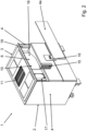
- FIG. 1 Designated by reference number 1, a system according to the invention is shown.
- the system 1 shown here comprises a kitchen furniture 2 with an upper worktop 3 and side panels 4, 4a, 4b.
- a hob 5 of the system 1 is embedded in the worktop 3.
- an air intake opening 11 of an extractor hood 6 ( Fig. 2 , Fig. 5 ) can be seen, which is arranged in the kitchen furniture 2 below the hob 5.
- the extractor hood 6 is used to extract cooking fumes 7 from above the hob 5 in the downward direction 8 by means of an air stream 9.
- the cooking fumes 2 rising are deflected downwards and drawn off via at least one air intake opening 11 of the extractor hood 6.
- the Figure 2 shows the system 1 according to Figure 1 in a first version.
- the extractor hood 6 of the system 1 has an extractor housing 10, which, in addition to the air intake opening 11, also has at least one air outlet 12 ( Fig. 6 ) for the air flow 9 ( Fig. 1 ) having.
- the trigger housing 10 is a Fan 13 ( Fig. 5 ) to generate the air flow 9 ( Fig. 1 ) arranged.
- a separating element 14 Fig. 7
- the air flow 9 ( Fig. 7 )
- a filter element 15 of the extractor hood 6 is arranged in the extractor housing 10 in the air flow between the fan 13 and the air outlet 12, which in Figure 2 shown taken from.
- This filter element 15, which is arranged downstream of the fan 13, preferably serves to reduce odors in the air flow 9.
- the filter element 15 is designed to be removable from the extractor housing 10 of the extractor hood 6.
- the kitchen furniture 2 has a panel 4a that can be removed and reinstalled without tools.
- an access opening 17 of the extractor housing 10 that can be opened and reclosed without tools via a closure flap 16 of the extractor housing 10 can be reached.
- access to the extraction housing 10 for manual removal of the filter element 15 is free, which enables a particularly simple change of the filter element 15.
- the panel 4a which can be removed and reinstalled without tools, is designed as a front panel 4a of the kitchen furniture 2 that adjoins the worktop 3.
- the access opening 17 is formed here in a front side wall 18 of the trigger housing 10.
- a magnetic holding element 19 is provided, with which the panel 4a is attached to the kitchen furniture 2 in a manually detachable manner.
- Either the panel 4a or the kitchen furniture 2 have a ferromagnetic counterpart to the magnetic holding element 19 so that the panel 4a can be held magnetically on the kitchen furniture 2.
- the panel 4a can also be attached to the kitchen furniture 2 via another easily detachable holding element.
- the Figure 3 shows the system 1 according to Figure 1 in a second embodiment, which differs at least partially from the first embodiment.
- the extractor hood 6 of the system 1 has an extractor housing 10, which, in addition to the air intake opening 11, also has at least one air outlet 12 ( Fig. 6 ) for the air flow 9 ( Fig. 1 ) has.
- a separating element 14 ( Fig. 7 ) arranged in the extractor housing 10.
- This separating element 14 ( Fig. 7 ) serves to separate one or more components of the cooking vapors 7, in particular fat and / or oil, from the air stream 9.
- the air stream is also from the air intake opening 11 via the separating element 14 ( Fig. 5 ) to the fan 13 ( Fig. 5 ) guided.
- the air flow is then supplied by the fan 13 ( Fig. 5 ) via the air outlet 12 ( Fig. 6 ) blown out of the trigger housing 10.
- a filter element 15 is also arranged in the extractor housing 10 of the extractor hood 6 in the air flow between the fan 13 and the air outlet 12.
- the filter element 15 arranged downstream of the fan 13 preferably serves to reduce odors in the air flow 9.
- the filter element 15 is also designed to be removable from the extractor housing 10 of the extractor hood 6.
- the kitchen furniture 2 has a panel 4b that can be removed and reinstalled without tools.
- a closure flap 16 ( Fig. 6 ) of the trigger housing 10 which can be opened and reclosed access opening 17 ( Fig. 6 ) of the trigger housing 10 can be reached.
- the panel 4b which can be removed and reassembled without tools, is designed as a drawer panel 4b of a drawer 20 of the kitchen furniture 2 arranged directly below the extractor housing 10.
- the drawer panel 4b can be removed from the drawer 20 in the kitchen furniture 2 and reassembled without tools, independently of the remaining drawer 20.
- the drawer panel 4b can be connected to the rest of the drawer 20 via a detachable snap connection.
- FIG. 4 An alternative to this is in Figure 4 shown where the drawer 20 together with the drawer panel 4b can be removed from the kitchen furniture 2 and reassembled without tools.
- the access opening 17 is advantageously formed in a lower base 21 of the trigger housing 10, as in the Figures 5 , 6 and 7 shown.
- the closure flap 16 can be opened at the access opening 17.
- the filter element 15 can then be changed very easily.
Landscapes
- Engineering & Computer Science (AREA)
- Chemical & Material Sciences (AREA)
- Combustion & Propulsion (AREA)
- Mechanical Engineering (AREA)
- General Engineering & Computer Science (AREA)
- Ventilation (AREA)
Applications Claiming Priority (1)
| Application Number | Priority Date | Filing Date | Title |
|---|---|---|---|
| DE102022123310.3A DE102022123310A1 (de) | 2022-09-13 | 2022-09-13 | System aus Küchenmöbel, Kochfeld und Dunstabzug |
Publications (1)
| Publication Number | Publication Date |
|---|---|
| EP4339519A1 true EP4339519A1 (fr) | 2024-03-20 |
Family
ID=88018261
Family Applications (1)
| Application Number | Title | Priority Date | Filing Date |
|---|---|---|---|
| EP23196781.1A Pending EP4339519A1 (fr) | 2022-09-13 | 2023-09-12 | Système constitué d'un meuble de cuisine, d'une plaque de cuisson et d'un hotte aspirante |
Country Status (2)
| Country | Link |
|---|---|
| EP (1) | EP4339519A1 (fr) |
| DE (1) | DE102022123310A1 (fr) |
Citations (3)
| Publication number | Priority date | Publication date | Assignee | Title |
|---|---|---|---|---|
| US4411254A (en) * | 1981-04-24 | 1983-10-25 | The Jenn-Air Corporation | Countertop range with proximity ventilation and electronic air cleaner |
| EP3722678A1 (fr) * | 2019-04-12 | 2020-10-14 | BSH Hausgeräte GmbH | Appareil combiné pourvu de plaque de cuisson et de hotte aspirante et de dispositif de cuisine |
| DE102020130485A1 (de) * | 2020-11-18 | 2022-05-19 | Miele & Cie. Kg | Umluftvorrichtung für ein Kochfeld und Funktionseinheit aus einem Kochfeld, einem Möbel und einer Umluftvorrichtung |
Family Cites Families (1)
| Publication number | Priority date | Publication date | Assignee | Title |
|---|---|---|---|---|
| DE102020213310B4 (de) * | 2019-12-19 | 2025-05-28 | Werkhaus GmbH & Co. KG | Lüftereinrichtung zum Fördern von Luft |
-
2022
- 2022-09-13 DE DE102022123310.3A patent/DE102022123310A1/de active Pending
-
2023
- 2023-09-12 EP EP23196781.1A patent/EP4339519A1/fr active Pending
Patent Citations (3)
| Publication number | Priority date | Publication date | Assignee | Title |
|---|---|---|---|---|
| US4411254A (en) * | 1981-04-24 | 1983-10-25 | The Jenn-Air Corporation | Countertop range with proximity ventilation and electronic air cleaner |
| EP3722678A1 (fr) * | 2019-04-12 | 2020-10-14 | BSH Hausgeräte GmbH | Appareil combiné pourvu de plaque de cuisson et de hotte aspirante et de dispositif de cuisine |
| DE102020130485A1 (de) * | 2020-11-18 | 2022-05-19 | Miele & Cie. Kg | Umluftvorrichtung für ein Kochfeld und Funktionseinheit aus einem Kochfeld, einem Möbel und einer Umluftvorrichtung |
Also Published As
| Publication number | Publication date |
|---|---|
| DE102022123310A1 (de) | 2024-03-14 |
Similar Documents
| Publication | Publication Date | Title |
|---|---|---|
| EP3978811A1 (fr) | Unité de hotte aspirante à monter en dessous d'une plaque de cuisson, unité de filtre anti-odeurs, système de hotte aspirante et procédé de fonctionnement d'un système de hotte aspirante | |
| EP1134501A1 (fr) | Hotte aspirante de buée | |
| DE202021105496U1 (de) | Kochfeldmodul | |
| EP3336438B1 (fr) | Hotte aspirante | |
| EP2772695B1 (fr) | Hotte aspirante | |
| DE102019109401B4 (de) | Lüftereinrichtung zum Ansaugen und Ableiten von Wrasen nach unterhalb eines Kochfeldes und Kochfeld | |
| WO2021244847A1 (fr) | Dispositif d'extraction de vapeur et système de surface de cuisson | |
| EP4043797A1 (fr) | Hotte aspirante dans plaque de cuisson | |
| EP4339519A1 (fr) | Système constitué d'un meuble de cuisine, d'une plaque de cuisson et d'un hotte aspirante | |
| EP2829808B1 (fr) | Hotte aspirante | |
| DE20122340U1 (de) | Dunstabzugshaube | |
| EP4151909B1 (fr) | Module de table de cuisson | |
| EP1128132A2 (fr) | Hotte aspirant la buée | |
| DE10241313A1 (de) | Dunstabzugshaube | |
| DE102017104198B4 (de) | Deckenhaltevorrichtung zur Arretierung einer Dunstabzugseinheit zum Absaugen von Wrasen, Dunstabzugseinheit zum Absaugen von Wrasen sowie Dunstabzugssystem mit einer solchen Dunstabzugseinheit und einer solchen Deckenhaltevorrichtung | |
| DE102018130963A1 (de) | Dunstabzugseinrichtung für eine Schrank- oder Küchenzeile | |
| EP0943871B1 (fr) | Hotte d'évacuation de fumée pour cuisine | |
| DE102004043069A1 (de) | Dunstabzugshaube | |
| DE19913001A1 (de) | Dunstabzugshaube | |
| EP3196556B1 (fr) | Hotte aspirante | |
| EP4481279A1 (fr) | Hotte aspirante et appareil combiné | |
| EP4339518A1 (fr) | Hotte aspirante et appareil combiné | |
| DE9416271U1 (de) | Dunstabzugsvorrichtung | |
| EP2955450B1 (fr) | Hotte aspirante | |
| EP1108959A1 (fr) | Hotte de ventilation pour cuisine |
Legal Events
| Date | Code | Title | Description |
|---|---|---|---|
| PUAI | Public reference made under article 153(3) epc to a published international application that has entered the european phase |
Free format text: ORIGINAL CODE: 0009012 |
|
| STAA | Information on the status of an ep patent application or granted ep patent |
Free format text: STATUS: THE APPLICATION HAS BEEN PUBLISHED |
|
| AK | Designated contracting states |
Kind code of ref document: A1 Designated state(s): AL AT BE BG CH CY CZ DE DK EE ES FI FR GB GR HR HU IE IS IT LI LT LU LV MC ME MK MT NL NO PL PT RO RS SE SI SK SM TR |
|
| STAA | Information on the status of an ep patent application or granted ep patent |
Free format text: STATUS: REQUEST FOR EXAMINATION WAS MADE |
|
| 17P | Request for examination filed |
Effective date: 20240920 |
|
| RBV | Designated contracting states (corrected) |
Designated state(s): AL AT BE BG CH CY CZ DE DK EE ES FI FR GB GR HR HU IE IS IT LI LT LU LV MC ME MK MT NL NO PL PT RO RS SE SI SK SM TR |