EP4339547A1 - Kreuzstromwärmetauscher mit gestapelten verteilerrohren - Google Patents
Kreuzstromwärmetauscher mit gestapelten verteilerrohren Download PDFInfo
- Publication number
- EP4339547A1 EP4339547A1 EP23184695.7A EP23184695A EP4339547A1 EP 4339547 A1 EP4339547 A1 EP 4339547A1 EP 23184695 A EP23184695 A EP 23184695A EP 4339547 A1 EP4339547 A1 EP 4339547A1
- Authority
- EP
- European Patent Office
- Prior art keywords
- inlet
- heat exchanger
- outlet
- tubes
- tube
- Prior art date
- Legal status (The legal status is an assumption and is not a legal conclusion. Google has not performed a legal analysis and makes no representation as to the accuracy of the status listed.)
- Granted
Links
Images


Classifications
-
- F—MECHANICAL ENGINEERING; LIGHTING; HEATING; WEAPONS; BLASTING
- F28—HEAT EXCHANGE IN GENERAL
- F28F—DETAILS OF HEAT-EXCHANGE AND HEAT-TRANSFER APPARATUS, OF GENERAL APPLICATION
- F28F9/00—Casings; Header boxes; Auxiliary supports for elements; Auxiliary members within casings
- F28F9/02—Header boxes; End plates
- F28F9/0219—Arrangements for sealing end plates into casing or header box; Header box sub-elements
- F28F9/0221—Header boxes or end plates formed by stacked elements
-
- F—MECHANICAL ENGINEERING; LIGHTING; HEATING; WEAPONS; BLASTING
- F28—HEAT EXCHANGE IN GENERAL
- F28F—DETAILS OF HEAT-EXCHANGE AND HEAT-TRANSFER APPARATUS, OF GENERAL APPLICATION
- F28F7/00—Elements not covered by group F28F1/00, F28F3/00 or F28F5/00
- F28F7/02—Blocks traversed by passages for heat-exchange media
-
- B—PERFORMING OPERATIONS; TRANSPORTING
- B33—ADDITIVE MANUFACTURING TECHNOLOGY
- B33Y—ADDITIVE MANUFACTURING, i.e. MANUFACTURING OF THREE-DIMENSIONAL [3D] OBJECTS BY ADDITIVE DEPOSITION, ADDITIVE AGGLOMERATION OR ADDITIVE LAYERING, e.g. BY 3D PRINTING, STEREOLITHOGRAPHY OR SELECTIVE LASER SINTERING
- B33Y80/00—Products made by additive manufacturing
-
- F—MECHANICAL ENGINEERING; LIGHTING; HEATING; WEAPONS; BLASTING
- F28—HEAT EXCHANGE IN GENERAL
- F28D—HEAT-EXCHANGE APPARATUS, NOT PROVIDED FOR IN ANOTHER SUBCLASS, IN WHICH THE HEAT-EXCHANGE MEDIA DO NOT COME INTO DIRECT CONTACT
- F28D7/00—Heat-exchange apparatus having stationary tubular conduit assemblies for both heat-exchange media, the media being in contact with different sides of a conduit wall
- F28D7/16—Heat-exchange apparatus having stationary tubular conduit assemblies for both heat-exchange media, the media being in contact with different sides of a conduit wall the conduits being arranged in parallel spaced relation
- F28D7/1615—Heat-exchange apparatus having stationary tubular conduit assemblies for both heat-exchange media, the media being in contact with different sides of a conduit wall the conduits being arranged in parallel spaced relation the conduits being inside a casing and extending at an angle to the longitudinal axis of the casing; the conduits crossing the conduit for the other heat exchange medium
-
- F—MECHANICAL ENGINEERING; LIGHTING; HEATING; WEAPONS; BLASTING
- F28—HEAT EXCHANGE IN GENERAL
- F28F—DETAILS OF HEAT-EXCHANGE AND HEAT-TRANSFER APPARATUS, OF GENERAL APPLICATION
- F28F1/00—Tubular elements; Assemblies of tubular elements
- F28F1/006—Tubular elements; Assemblies of tubular elements with variable shape, e.g. with modified tube ends, with different geometrical features
-
- F—MECHANICAL ENGINEERING; LIGHTING; HEATING; WEAPONS; BLASTING
- F28—HEAT EXCHANGE IN GENERAL
- F28F—DETAILS OF HEAT-EXCHANGE AND HEAT-TRANSFER APPARATUS, OF GENERAL APPLICATION
- F28F9/00—Casings; Header boxes; Auxiliary supports for elements; Auxiliary members within casings
- F28F9/02—Header boxes; End plates
- F28F9/026—Header boxes; End plates with static flow control means, e.g. with means for uniformly distributing heat exchange media into conduits
- F28F9/0265—Header boxes; End plates with static flow control means, e.g. with means for uniformly distributing heat exchange media into conduits by using guiding means or impingement means inside the header box
- F28F9/0268—Header boxes; End plates with static flow control means, e.g. with means for uniformly distributing heat exchange media into conduits by using guiding means or impingement means inside the header box in the form of multiple deflectors for channeling the heat exchange medium
-
- F—MECHANICAL ENGINEERING; LIGHTING; HEATING; WEAPONS; BLASTING
- F28—HEAT EXCHANGE IN GENERAL
- F28F—DETAILS OF HEAT-EXCHANGE AND HEAT-TRANSFER APPARATUS, OF GENERAL APPLICATION
- F28F9/00—Casings; Header boxes; Auxiliary supports for elements; Auxiliary members within casings
- F28F9/02—Header boxes; End plates
- F28F9/026—Header boxes; End plates with static flow control means, e.g. with means for uniformly distributing heat exchange media into conduits
- F28F9/027—Header boxes; End plates with static flow control means, e.g. with means for uniformly distributing heat exchange media into conduits in the form of distribution pipes
- F28F9/0273—Header boxes; End plates with static flow control means, e.g. with means for uniformly distributing heat exchange media into conduits in the form of distribution pipes with multiple holes
-
- F—MECHANICAL ENGINEERING; LIGHTING; HEATING; WEAPONS; BLASTING
- F28—HEAT EXCHANGE IN GENERAL
- F28F—DETAILS OF HEAT-EXCHANGE AND HEAT-TRANSFER APPARATUS, OF GENERAL APPLICATION
- F28F9/00—Casings; Header boxes; Auxiliary supports for elements; Auxiliary members within casings
- F28F9/22—Arrangements for directing heat-exchange media into successive compartments, e.g. arrangements of guide plates
-
- F—MECHANICAL ENGINEERING; LIGHTING; HEATING; WEAPONS; BLASTING
- F28—HEAT EXCHANGE IN GENERAL
- F28F—DETAILS OF HEAT-EXCHANGE AND HEAT-TRANSFER APPARATUS, OF GENERAL APPLICATION
- F28F9/00—Casings; Header boxes; Auxiliary supports for elements; Auxiliary members within casings
- F28F9/22—Arrangements for directing heat-exchange media into successive compartments, e.g. arrangements of guide plates
- F28F2009/222—Particular guide plates, baffles or deflectors, e.g. having particular orientation relative to an elongated casing or conduit
-
- F—MECHANICAL ENGINEERING; LIGHTING; HEATING; WEAPONS; BLASTING
- F28—HEAT EXCHANGE IN GENERAL
- F28F—DETAILS OF HEAT-EXCHANGE AND HEAT-TRANSFER APPARATUS, OF GENERAL APPLICATION
- F28F2250/00—Arrangements for modifying the flow of the heat exchange media, e.g. flow guiding means; Particular flow patterns
- F28F2250/10—Particular pattern of flow of the heat exchange media
- F28F2250/106—Particular pattern of flow of the heat exchange media with cross flow
Definitions
- the embodiments are directed to heat exchangers and more specifically to a crossflow heat exchanger with stacked distribution tubes.
- Counterflow is a configuration for a heat exchanger that may be configured to maximize heat transfer.
- the configuration may reduce thermal stress by enabling a lower local temperature difference.
- Such configurations may result in a high pressure drop, which could also induce stress challenges within the heat exchanger.
- a heat exchanger including: a core having a first side and a second side, a top and a bottom; an inlet header located at the top of the first side, the inlet header having plural inlet tubes, the plural inlet tubes include a first inlet tube stacked against the first side of the heat exchanger, a second inlet tube stacked against the first inlet tube and a third inlet tube stacked against the second inlet tube; an outlet header located at the bottom of the second side, the outlet header having plural outlet tubes, the plural outlet tubes include a first outlet tube stacked against the second side of the heat exchanger, a second outlet tube stacked against the first outlet tube and a third outlet tube stacked against the second outlet tube, wherein the first inlet and outlet tubes have a same length as each other, the second inlet and outlet tubes have the same length as each other and are longer than the first inlet and outlet tubes, and the third inlet and outlet tubes have a same length as each other and are longer than the second inlet and outlet tubes; and core channels within the
- the inlet tubes and the outlet tubes each define a header end and a terminal end; and each tube tapers towards the terminal end.
- the heat exchanger is a counterflow heat exchanger.
- the inlet tubes are connected to a same number of the core channels as each other; and the outlet tubes are connected to a same number of the core channels as each other.
- the heat exchanger includes a first baffle on one side of the core channels; and a second baffle on another side of the core channels, wherein the first and second baffles are configured to direct a gas flow between the first side and the second side of the heat exchanger.
- the heat exchanger includes a first set of heat fins that are coupled to the core channels and the first baffle; and a second set of heat finds that are coupled to the core channels and the second baffle.
- the heat exchanger includes a case extending from the first side to the second side to surround the core and form a flow boundary for the gas flow.
- the tubes and channels have a round cross section.
- a method of manufacturing a heat exchanger including: defining the heat exchanger to include: a core having a first side and a second side, a top and a bottom; an inlet header located at the top of the first side, the inlet header having plural inlet tubes, the plural inlet tubes include a first inlet tube stacked against the first side of the heat exchanger, a second inlet tube stacked against the first inlet tube and a third inlet tube stacked against the second inlet tube; an outlet header located at the bottom of the second side, the outlet header having plural outlet tubes, the plural outlet tubes include a first outlet tube stacked against the second side of the heat exchanger, a second outlet tube stacked against the first outlet tube and a third outlet tube stacked against the second outlet tube, wherein the first inlet and outlet tubes have a same length as each other, the second inlet and outlet tubes have the same length as each other and are longer than the first inlet and outlet tubes, and the third inlet and outlet tubes have a same length as each other and are
- the method includes defining the heat exchanger such that: the inlet tubes and the outlet tubes each define a header end and a terminal end; and each tube tapers towards the terminal end.
- the method includes defining the heat exchanger such that the heat exchanger is a crossflow heat exchanger.
- the method includes defining the heat exchanger such that: the inlet tubes are connected to a same number of the core channels as each other; and the outlet tubes are connected to a same number of the core channels as each other.
- the method includes defining the heat exchanger to include: a first baffle on one side of the core channels; and a second baffle on another side of the core channels, wherein the first and second baffles are configured to direct a gas flow between the first side and the second side of the heat exchanger.
- the method includes defining the heat exchanger to include: a first set of heat fins that are coupled to the core channels and the first baffle; and a second set of heat finds that are coupled to the core channels and the second baffle.
- the method includes defining the heat exchanger to include a case extending from the first side to the second side to surround the core and form a flow boundary for the gas flow.
- tubes and channels have a round cross section.
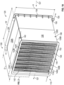
- the embodiments are directed to a counterflow heat exchanger 100 configured to reduce a pressure drop, and increase heat transfer, in the working fluid 105.
- the heat exchanger 100 therefore enables a greater amount of heat transfer between the working fluid 105 and a gas flow 107 through the heat exchanger 100.
- the heat exchanger 100 may be an additively manufactured, or conventionally manufactured, crossflow heat exchanger having a first end 110 and a second end 120 separated from each other by a depth D of the heat exchanger 100.
- the first end 110 is a front end and the second end 120 is a back end of the heat exchanger 100.
- a case or shell 130 surrounds a core 108 of the heat exchanger 100 and the gas flow 107 may flow through the core 108 of the heat exchanger 100, e.g., through the shell 130. That is, the shell 130 forms a flow boundary through the core 108 of the heat exchanger 100.
- An outer shape of the heat exchanger 100 is square, though other shapes are within the scope of the embodiments.
- the shell 130 defines a top 130A, a bottom 130B, and opposite sides 130C, 130D of the heat exchanger 100.
- the top 130A and bottom 130B are separated from each other by a height H of the heat exchanger 100.
- the sides 130C, 130D are separated from each other by a width W of the heat exchanger 100.
- the heat exchanger 100 has a first header 140, which may be an inlet header, on the top of the first end 110.
- a second header 150 which may be an outlet header, is on the bottom of the second end 120 of the heat exchanger 100.
- the first header 140 has sets of inlet distribution tubes (inlet tubes) 142 at the inlet transition region 110A of the first end 110 of the heat exchanger 100, e.g., at the transition to the core flow of the working fluid 105.
- the sets of inlet tubes 142 includes first and second sets 142A, 142B that are widthwise spaced apart from each other and extend heightwise along the first end 110 of the heat exchanger 100.
- the second header 150 has sets of outlet distribution tubes (outlet tubes) 144 at the outlet transition region 110B of the second end 120 of the heat exchanger 100, e.g., at the transition from the core flow of the working fluid 105.
- the sets of outlet tubes 144 includes first and second sets 144A, 144B that are widthwise spaced apart from each other and extend heightwise along the second end 120 of the heat exchanger 100.
- the sets of tubes on the of the first and second headers 140, 150 are fluidly coupled to each other as described in greater detail below.
- the first and second headers 140, 150 may be utilized to transport the working fluid 105 though the heat exchanger 100, e.g., between the first and second ends 110, 120 of the heat exchanger 100.
- a third header 145 and a fourth header 155 are fluidly coupled to each other, similarly to the first and second headers 140, 150.
- the third header 145 which may be another inlet header, is located at the bottom of the first end 110 of the heat exchanger 100.
- the fourth header 155 which may be another outlet header, is located at the top of the second end 120 of the heat exchanger 100. That is, the third and fourth headers 145, 155 are on heightwise opposite sides of the heat exchanger 100 compared with the first and second headers 140, 150.
- the third header 145 has sets of inlet tubes 146, including first and second sets 146A, 146B, that are widthwise spaced apart from each other and extend heightwise along the first end 110 of the heat exchanger 100.
- the inlet tubes 146 are fluidly coupled with sets outlet tubes 148, including first and second sets 148A, 148B of the fourth header 155.
- the sets of outlet tubes 148 are widthwise spaced apart from each other and extend heightwise along the second end 120 of the heat exchanger 100.
- the third and fourth headers 145, 155 have the same function of transporting the working fluid 105 through the heat exchanger 100 as the first and second headers 140, 150. However, the third and fourth headers 145, 155 are fluidly isolated from the first and second headers 140, 150. It is to be appreciated that the third and fourth headers 145, 155, and related core flow therebetween of the working fluid 105, is optional.
- a first perimeter lip 152 extends around a perimeter of the first end 110 and a second perimeter lip 154 extends around a perimeter of the second end 120.
- the perimeter lips 152, 154 are sized to be large enough to provide a sealing surface for gas flow 107.
- the first and second headers 140, 150 are configured the same as each other, so focus will be on the first header 140.
- the first header 140 has an inlet manifold (or manifold) 170.
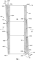
- the first set of inlet tubes 142A has plural, e.g., two or more, though illustrated as three inlet tubes including first, second and third inlet tubes 142A1-A3 that are stacked, one on top of the other.
- Each of the inlet tubes 142A1-142A3 has a header end (or manifold end) 180A-C.
- the first inlet tube 142A1 is an interior tube
- the second inlet tube 142A2 is an intermediate tube
- the third inlet tube 142A3 is an exterior tube.
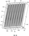
- Core channels (or channels) 190 trace a straight line path through the core of the heat exchanger 100 and fluidly couple the inlet tubes 142 to the outlet tubes 144, as discussed in greater detail below.
- the channels 190 are fluidly isolated from each other within the core 108.
- Baffles 200, 210 e.g., first and second baffles 200, 210, may be adjacent to each side of the channels 190 and extend through the depth of the heat exchanger 100.
- Heat fins 215 may be formed to extend between the channels 190 and the baffles 200.
- there may be a plurality of sets of the channels 190A, 190B, 190C connected to the set of inlet tubes 142 via ports 195 in the inlet tubes 142.
- each of the inlet tubes 142A1-A3 on the first end 110 of the heat exchanger 110 has a terminal end 182A-C. From the header ends 180A-C to the terminal ends 182A-C, the third inlet tube 142A3 is longer than the second inlet tube 142A2, which is longer than the first inlet tube 142A1.
- the first inlet tube 142A1 is connected to the core channels 190 along its length, e.g., along the heightwise direction.
- the second inlet tube 142A2 is connected to channels 190 along its length that extends past the first inlet tube 142A1, e.g., in the heightwise downward direction.
- the third inlet tube 142A3 is connected to channels 190 along its length that extends past the second inlet tube 142A2, in the heightwise downward direction.
- the inlet tubes 142 are connected to a same number of channels 190 as each other.
- the inlet tubes 142 taper towards the terminal ends 182A-C.
- the second header 150 has an outlet manifold (or manifold) 220.
- the first set of outlet tubes 144A has plural, e.g., two or more, though illustrated as three tubes including first, second and third outlet tubes 144A1-A3 that are stacked, one on top of the other.
- Each of the outlet tubes 144A1-144A3 has a header end (or manifold end) 230A-C.
- the first outlet tube 144A1 is an interior tube
- the second outlet tube 144A2 is an intermediate tube
- the third outlet tube 144A3 is an exterior tube.
- Each of the outlet tubes 144A1-A3 has a terminal end 240A-C. From the manifold 220 to the terminal ends 240A-C, the third outlet tube 144A3 is longer than the second outlet tube 144A2, which is longer than the first outlet tube 144A1.
- the first outlet tube 144A1 is connected to channels 190 along its length.
- the second outlet tube 144A2 is connected to channels 190 along its length that extends past the first outlet tube 144A1, e.g., in the heightwise upward direction.
- the third outlet tube 144A3 is connected to channels 190 along its length that extends past the second outlet tube 144A2, in the heightwise upward direction.
- the first inlet and outlet tubes 142A1, 144A1 may be the same length as each other, the second inlet and outlet tubes 142A2, 144A2 may be the same length as each other, and the third inlet and outlet tubes 142A3, 144A3 may be the same length as each other.
- the outlet tubes 144 taper towards the terminal ends 240A-C. As indicated, the outlet tubes 144 are the same configuration as the inlet tubes 142, except that they are inverted in the heightwise direction. As with the inlet tubes 142, by limiting a length and distribution requirements of each outlet tube 144, the pressure losses are reduced. In addition, by reducing the diameter of each outlet tube 144 towards its terminal ends 240A-C, more uniform flow through channels 190 is produced. Thus the efficiency of heat transfer from the working fluid 105 to the gas flow 107 in the core 108 is further increased.
- the channels 190 fluidly couple the first inlet tube 142A1 with the third outlet tube 144A3, the second inlet tube 142A2 with the second outlet tube 144A2 and the third inlet tube 142A3 with the first outlet tube 144A2.
- the channels 190 also fluidly couple the terminal end 182A of the first inlet tube 142A1 with the terminal end 240B of the second outlet tube 144A2 and the terminal end 182B of the second inlet tube 142A2 with the terminal end 240A of the first outlet tube 144B2. This fluid coupling configuration helps to maintain equal flow within the tubes.
- the above embodiments provide a heat exchanger 100 that is compact and efficient.
- the heat exchanger 100 is suitable for high pressure and temperature applications.
- fluid 105 will generally be at a higher pressure, such as 10 bar, and density than fluid 107.
- the stacked design of the tubes provides a direct path for the working fluid 105 to enter the core channels 190, without impeding fluid 107, reducing pressure drop and improving heat transfer.
- the tubes and channels have a round cross section.
Landscapes
- Engineering & Computer Science (AREA)
- Physics & Mathematics (AREA)
- Thermal Sciences (AREA)
- Mechanical Engineering (AREA)
- General Engineering & Computer Science (AREA)
- Chemical & Material Sciences (AREA)
- Manufacturing & Machinery (AREA)
- Materials Engineering (AREA)
- Geometry (AREA)
- Heat-Exchange Devices With Radiators And Conduit Assemblies (AREA)
Applications Claiming Priority (1)
| Application Number | Priority Date | Filing Date | Title |
|---|---|---|---|
| US17/945,135 US12130097B2 (en) | 2022-09-15 | 2022-09-15 | Crossflow heat exchanger with stacked distribution tubes |
Publications (2)
| Publication Number | Publication Date |
|---|---|
| EP4339547A1 true EP4339547A1 (de) | 2024-03-20 |
| EP4339547B1 EP4339547B1 (de) | 2025-08-27 |
Family
ID=87245637
Family Applications (1)
| Application Number | Title | Priority Date | Filing Date |
|---|---|---|---|
| EP23184695.7A Active EP4339547B1 (de) | 2022-09-15 | 2023-07-11 | Kreuzstromwärmetauscher mit gestapelten verteilerrohren |
Country Status (2)
| Country | Link |
|---|---|
| US (1) | US12130097B2 (de) |
| EP (1) | EP4339547B1 (de) |
Families Citing this family (1)
| Publication number | Priority date | Publication date | Assignee | Title |
|---|---|---|---|---|
| US12435932B2 (en) * | 2022-10-21 | 2025-10-07 | General Electric Company | Heat exchanger assembly formed of a lattice structure with a plurality of shell structure unit cells |
Citations (6)
| Publication number | Priority date | Publication date | Assignee | Title |
|---|---|---|---|---|
| FR1128148A (fr) * | 1955-06-27 | 1957-01-02 | Collecteur à cloisons de répartition | |
| CH558510A (de) * | 1972-07-27 | 1975-01-31 | Transformatoren Union Ag | Waermetauscher zur rueckkuehlung der kuehlfluessigkeit eines transformators oder einer drossel. |
| US5901785A (en) * | 1996-03-29 | 1999-05-11 | Sanden Corporation | Heat exchanger with a distribution device capable of uniformly distributing a medium to a plurality of exchanger tubes |
| US20170089643A1 (en) * | 2015-09-25 | 2017-03-30 | Westinghouse Electric Company, Llc. | Heat Exchanger |
| US20210231383A1 (en) * | 2020-01-24 | 2021-07-29 | Hamilton Sundstrand Corporation | Fractal heat exchanger |
| US11268770B2 (en) * | 2019-09-06 | 2022-03-08 | Hamilton Sunstrand Corporation | Heat exchanger with radially converging manifold |
Family Cites Families (27)
| Publication number | Priority date | Publication date | Assignee | Title |
|---|---|---|---|---|
| US2044455A (en) * | 1935-05-16 | 1936-06-16 | Young Radiator Co | Distributing head for evaporators |
| US2099186A (en) * | 1935-12-24 | 1937-11-16 | Reuben H Anderegg | Evaporator coil |
| DE4319192A1 (de) * | 1993-06-09 | 1994-12-15 | Behr Gmbh & Co | Verfahren zur Herstellung von Kältemittelverteilern, insbesondere für Verdampfer einer Klimaanlage eines Kraftfahrzeuges |
| JPH09257386A (ja) * | 1996-03-22 | 1997-10-03 | Sanden Corp | 分配装置及びそれを備えた熱交換器 |
| EP1079194B1 (de) * | 1999-08-23 | 2004-01-21 | Nippon Shokubai Co., Ltd. | Verfahren zur Verhinderung von Verstopfungen in einem Plattenwärmetauscher |
| JP2002303499A (ja) * | 2001-03-30 | 2002-10-18 | Hisaka Works Ltd | プレート式熱交換器 |
| US6736191B1 (en) * | 2001-10-09 | 2004-05-18 | Power Engineering Contractors, Inc. | Heat exchanger having longitudinal structure and mounting for placement in seawater under piers for heating and cooling of buildings |
| JP2003161547A (ja) * | 2001-11-21 | 2003-06-06 | Kobe Steel Ltd | 蒸発器用プレート式熱交換器 |
| DE10349150A1 (de) * | 2003-10-17 | 2005-05-19 | Behr Gmbh & Co. Kg | Wärmeübertrager, insbesondere für Kraftfahrzeuge |
| CN101487669B (zh) * | 2008-01-17 | 2012-08-22 | 开利公司 | 包括多管式分配器的热交换器 |
| CN102027308A (zh) * | 2008-05-16 | 2011-04-20 | 开利公司 | 具有增强的制冷剂分布的微通道热交换器 |
| CN101788242A (zh) * | 2009-03-25 | 2010-07-28 | 三花丹佛斯(杭州)微通道换热器有限公司 | 用于热交换器的制冷剂分配器和热交换器 |
| JP5677220B2 (ja) * | 2011-07-11 | 2015-02-25 | 日立アプライアンス株式会社 | 冷凍サイクル装置 |
| US9551540B2 (en) * | 2011-11-22 | 2017-01-24 | Daikin Industries, Ltd. | Heat exchanger |
| EP3033579B1 (de) * | 2013-08-12 | 2017-08-02 | Carrier Corporation | Wärmetauscher und strömungsverteiler |
| CN104764256A (zh) * | 2015-03-31 | 2015-07-08 | 广东美的暖通设备有限公司 | 热换器及具有其的多联机系统 |
| CN106996706A (zh) * | 2016-01-22 | 2017-08-01 | 丹佛斯微通道换热器(嘉兴)有限公司 | 板式换热器 |
| US20170363361A1 (en) * | 2016-06-17 | 2017-12-21 | Hamilton Sundstrand Corporation | Header for a heat exchanger |
| DE102016216245A1 (de) * | 2016-08-30 | 2018-03-01 | Zf Friedrichshafen Ag | Anordnung zur Fluidtemperierung |
| US10502254B2 (en) | 2017-07-26 | 2019-12-10 | The Boeing Company | Integral nut-retaining cradle for a nut plate assembly and methods of manufacturing using additive manufacturing |
| US10712526B2 (en) | 2017-12-14 | 2020-07-14 | Raytheon Company | Optical mount with tilt adjustment |
| US10746138B2 (en) * | 2018-04-30 | 2020-08-18 | Progress Rail Locomotive Inc. | Hollow fin tube structure at inlet of EGR cooler |
| US10816282B2 (en) * | 2018-09-12 | 2020-10-27 | Hamilton Sunstrand Corporation | Fluid flow management assembly for heat exchanger |
| US11022373B2 (en) * | 2019-01-08 | 2021-06-01 | Meggitt Aerospace Limited | Heat exchangers and methods of making the same |
| KR102235402B1 (ko) * | 2019-08-13 | 2021-04-02 | 엘지전자 주식회사 | 냉매 분배의 균일성이 향상된 열교환기 |
| GB201916349D0 (en) | 2019-11-11 | 2019-12-25 | Rolls Royce Plc | Bracket |
| US11584504B2 (en) | 2019-12-12 | 2023-02-21 | Textron Innovations, Inc. | Quick attach bracket |
-
2022
- 2022-09-15 US US17/945,135 patent/US12130097B2/en active Active
-
2023
- 2023-07-11 EP EP23184695.7A patent/EP4339547B1/de active Active
Patent Citations (6)
| Publication number | Priority date | Publication date | Assignee | Title |
|---|---|---|---|---|
| FR1128148A (fr) * | 1955-06-27 | 1957-01-02 | Collecteur à cloisons de répartition | |
| CH558510A (de) * | 1972-07-27 | 1975-01-31 | Transformatoren Union Ag | Waermetauscher zur rueckkuehlung der kuehlfluessigkeit eines transformators oder einer drossel. |
| US5901785A (en) * | 1996-03-29 | 1999-05-11 | Sanden Corporation | Heat exchanger with a distribution device capable of uniformly distributing a medium to a plurality of exchanger tubes |
| US20170089643A1 (en) * | 2015-09-25 | 2017-03-30 | Westinghouse Electric Company, Llc. | Heat Exchanger |
| US11268770B2 (en) * | 2019-09-06 | 2022-03-08 | Hamilton Sunstrand Corporation | Heat exchanger with radially converging manifold |
| US20210231383A1 (en) * | 2020-01-24 | 2021-07-29 | Hamilton Sundstrand Corporation | Fractal heat exchanger |
Also Published As
| Publication number | Publication date |
|---|---|
| US20240093952A1 (en) | 2024-03-21 |
| EP4339547B1 (de) | 2025-08-27 |
| US12130097B2 (en) | 2024-10-29 |
Similar Documents
| Publication | Publication Date | Title |
|---|---|---|
| US11965699B2 (en) | Heat exchangers | |
| EP3211358B1 (de) | Wärmetauscherkanäle | |
| US11454448B2 (en) | Enhanced heat transfer surface | |
| EP0021651A1 (de) | Jalousieartige Rippen für Wärmeaustauscher | |
| CN107532868B (zh) | 热交换器的罐构造及其制造方法 | |
| KR20120042854A (ko) | 열교환기 | |
| EP1271084A3 (de) | Wärmetauscher | |
| US6644392B2 (en) | Heat exchanger and a method of manufacturing a heat exchanger | |
| CN103890524A (zh) | 特别用于机动车辆的热交换器 | |
| CN103608639B (zh) | 翅片管型热交换器 | |
| US20170205156A1 (en) | Heat exchangers | |
| EP4339547A1 (de) | Kreuzstromwärmetauscher mit gestapelten verteilerrohren | |
| EP3009781B1 (de) | Wärmetauscher | |
| JP2004225961A (ja) | マルチフロー型熱交換器 | |
| US20030131979A1 (en) | Oil cooler | |
| CN219677372U (zh) | 一种换热装置及电池换热系统 | |
| JP3049386B2 (ja) | 複合熱交換器 | |
| EP4425082B1 (de) | Mikrokanalwärmetauscher | |
| US5634519A (en) | Heat exchanger, especially for cooling a high temperature air stream | |
| US20070000652A1 (en) | Heat exchanger with dimpled tube surfaces | |
| KR102855351B1 (ko) | 열교환기 | |
| US20250052520A1 (en) | Microchannel heat exchanger group and air conditioning system having same | |
| US7721795B2 (en) | Heat exchanger, especially charge-air/coolant cooler | |
| US6446715B2 (en) | Flat heat exchange tubes | |
| EP3534104B1 (de) | Wärmetauscher |
Legal Events
| Date | Code | Title | Description |
|---|---|---|---|
| PUAI | Public reference made under article 153(3) epc to a published international application that has entered the european phase |
Free format text: ORIGINAL CODE: 0009012 |
|
| STAA | Information on the status of an ep patent application or granted ep patent |
Free format text: STATUS: THE APPLICATION HAS BEEN PUBLISHED |
|
| AK | Designated contracting states |
Kind code of ref document: A1 Designated state(s): AL AT BE BG CH CY CZ DE DK EE ES FI FR GB GR HR HU IE IS IT LI LT LU LV MC ME MK MT NL NO PL PT RO RS SE SI SK SM TR |
|
| STAA | Information on the status of an ep patent application or granted ep patent |
Free format text: STATUS: REQUEST FOR EXAMINATION WAS MADE |
|
| 17P | Request for examination filed |
Effective date: 20240910 |
|
| RBV | Designated contracting states (corrected) |
Designated state(s): AL AT BE BG CH CY CZ DE DK EE ES FI FR GB GR HR HU IE IS IT LI LT LU LV MC ME MK MT NL NO PL PT RO RS SE SI SK SM TR |
|
| GRAP | Despatch of communication of intention to grant a patent |
Free format text: ORIGINAL CODE: EPIDOSNIGR1 |
|
| STAA | Information on the status of an ep patent application or granted ep patent |
Free format text: STATUS: GRANT OF PATENT IS INTENDED |
|
| RIC1 | Information provided on ipc code assigned before grant |
Ipc: B33Y 80/00 20150101ALI20250204BHEP Ipc: F28F 9/02 20060101AFI20250204BHEP |
|
| INTG | Intention to grant announced |
Effective date: 20250306 |
|
| GRAS | Grant fee paid |
Free format text: ORIGINAL CODE: EPIDOSNIGR3 |
|
| GRAA | (expected) grant |
Free format text: ORIGINAL CODE: 0009210 |
|
| STAA | Information on the status of an ep patent application or granted ep patent |
Free format text: STATUS: THE PATENT HAS BEEN GRANTED |
|
| AK | Designated contracting states |
Kind code of ref document: B1 Designated state(s): AL AT BE BG CH CY CZ DE DK EE ES FI FR GB GR HR HU IE IS IT LI LT LU LV MC ME MK MT NL NO PL PT RO RS SE SI SK SM TR |
|
| REG | Reference to a national code |
Ref country code: CH Ref legal event code: EP |
|
| REG | Reference to a national code |
Ref country code: DE Ref legal event code: R096 Ref document number: 602023006038 Country of ref document: DE |
|
| REG | Reference to a national code |
Ref country code: IE Ref legal event code: FG4D |
|
| REG | Reference to a national code |
Ref country code: NL Ref legal event code: MP Effective date: 20250827 |
|
| PG25 | Lapsed in a contracting state [announced via postgrant information from national office to epo] |
Ref country code: IS Free format text: LAPSE BECAUSE OF FAILURE TO SUBMIT A TRANSLATION OF THE DESCRIPTION OR TO PAY THE FEE WITHIN THE PRESCRIBED TIME-LIMIT Effective date: 20251227 |
|
| PG25 | Lapsed in a contracting state [announced via postgrant information from national office to epo] |
Ref country code: NO Free format text: LAPSE BECAUSE OF FAILURE TO SUBMIT A TRANSLATION OF THE DESCRIPTION OR TO PAY THE FEE WITHIN THE PRESCRIBED TIME-LIMIT Effective date: 20251127 |
|
| REG | Reference to a national code |
Ref country code: LT Ref legal event code: MG9D |
|
| PG25 | Lapsed in a contracting state [announced via postgrant information from national office to epo] |
Ref country code: PT Free format text: LAPSE BECAUSE OF FAILURE TO SUBMIT A TRANSLATION OF THE DESCRIPTION OR TO PAY THE FEE WITHIN THE PRESCRIBED TIME-LIMIT Effective date: 20251229 |
|
| PG25 | Lapsed in a contracting state [announced via postgrant information from national office to epo] |
Ref country code: FI Free format text: LAPSE BECAUSE OF FAILURE TO SUBMIT A TRANSLATION OF THE DESCRIPTION OR TO PAY THE FEE WITHIN THE PRESCRIBED TIME-LIMIT Effective date: 20250827 |
|
| PG25 | Lapsed in a contracting state [announced via postgrant information from national office to epo] |
Ref country code: HR Free format text: LAPSE BECAUSE OF FAILURE TO SUBMIT A TRANSLATION OF THE DESCRIPTION OR TO PAY THE FEE WITHIN THE PRESCRIBED TIME-LIMIT Effective date: 20250827 Ref country code: NL Free format text: LAPSE BECAUSE OF FAILURE TO SUBMIT A TRANSLATION OF THE DESCRIPTION OR TO PAY THE FEE WITHIN THE PRESCRIBED TIME-LIMIT Effective date: 20250827 |
|
| PG25 | Lapsed in a contracting state [announced via postgrant information from national office to epo] |
Ref country code: GR Free format text: LAPSE BECAUSE OF FAILURE TO SUBMIT A TRANSLATION OF THE DESCRIPTION OR TO PAY THE FEE WITHIN THE PRESCRIBED TIME-LIMIT Effective date: 20251128 |
|
| PG25 | Lapsed in a contracting state [announced via postgrant information from national office to epo] |
Ref country code: SE Free format text: LAPSE BECAUSE OF FAILURE TO SUBMIT A TRANSLATION OF THE DESCRIPTION OR TO PAY THE FEE WITHIN THE PRESCRIBED TIME-LIMIT Effective date: 20250827 |
|
| PG25 | Lapsed in a contracting state [announced via postgrant information from national office to epo] |
Ref country code: LV Free format text: LAPSE BECAUSE OF FAILURE TO SUBMIT A TRANSLATION OF THE DESCRIPTION OR TO PAY THE FEE WITHIN THE PRESCRIBED TIME-LIMIT Effective date: 20250827 |
|
| PG25 | Lapsed in a contracting state [announced via postgrant information from national office to epo] |
Ref country code: PL Free format text: LAPSE BECAUSE OF FAILURE TO SUBMIT A TRANSLATION OF THE DESCRIPTION OR TO PAY THE FEE WITHIN THE PRESCRIBED TIME-LIMIT Effective date: 20250827 Ref country code: BG Free format text: LAPSE BECAUSE OF FAILURE TO SUBMIT A TRANSLATION OF THE DESCRIPTION OR TO PAY THE FEE WITHIN THE PRESCRIBED TIME-LIMIT Effective date: 20250827 |
|
| PG25 | Lapsed in a contracting state [announced via postgrant information from national office to epo] |
Ref country code: RS Free format text: LAPSE BECAUSE OF FAILURE TO SUBMIT A TRANSLATION OF THE DESCRIPTION OR TO PAY THE FEE WITHIN THE PRESCRIBED TIME-LIMIT Effective date: 20251127 |
|
| PG25 | Lapsed in a contracting state [announced via postgrant information from national office to epo] |
Ref country code: ES Free format text: LAPSE BECAUSE OF FAILURE TO SUBMIT A TRANSLATION OF THE DESCRIPTION OR TO PAY THE FEE WITHIN THE PRESCRIBED TIME-LIMIT Effective date: 20250827 |
|
| REG | Reference to a national code |
Ref country code: AT Ref legal event code: MK05 Ref document number: 1830343 Country of ref document: AT Kind code of ref document: T Effective date: 20250827 |
|
| PG25 | Lapsed in a contracting state [announced via postgrant information from national office to epo] |
Ref country code: SM Free format text: LAPSE BECAUSE OF FAILURE TO SUBMIT A TRANSLATION OF THE DESCRIPTION OR TO PAY THE FEE WITHIN THE PRESCRIBED TIME-LIMIT Effective date: 20250827 |
|
| PG25 | Lapsed in a contracting state [announced via postgrant information from national office to epo] |
Ref country code: DK Free format text: LAPSE BECAUSE OF FAILURE TO SUBMIT A TRANSLATION OF THE DESCRIPTION OR TO PAY THE FEE WITHIN THE PRESCRIBED TIME-LIMIT Effective date: 20250827 |
|
| PG25 | Lapsed in a contracting state [announced via postgrant information from national office to epo] |
Ref country code: AT Free format text: LAPSE BECAUSE OF FAILURE TO SUBMIT A TRANSLATION OF THE DESCRIPTION OR TO PAY THE FEE WITHIN THE PRESCRIBED TIME-LIMIT Effective date: 20250827 |
|
| PG25 | Lapsed in a contracting state [announced via postgrant information from national office to epo] |
Ref country code: IT Free format text: LAPSE BECAUSE OF FAILURE TO SUBMIT A TRANSLATION OF THE DESCRIPTION OR TO PAY THE FEE WITHIN THE PRESCRIBED TIME-LIMIT Effective date: 20250827 |
|
| PG25 | Lapsed in a contracting state [announced via postgrant information from national office to epo] |
Ref country code: CZ Free format text: LAPSE BECAUSE OF FAILURE TO SUBMIT A TRANSLATION OF THE DESCRIPTION OR TO PAY THE FEE WITHIN THE PRESCRIBED TIME-LIMIT Effective date: 20250827 |
|
| PG25 | Lapsed in a contracting state [announced via postgrant information from national office to epo] |
Ref country code: EE Free format text: LAPSE BECAUSE OF FAILURE TO SUBMIT A TRANSLATION OF THE DESCRIPTION OR TO PAY THE FEE WITHIN THE PRESCRIBED TIME-LIMIT Effective date: 20250827 Ref country code: SK Free format text: LAPSE BECAUSE OF FAILURE TO SUBMIT A TRANSLATION OF THE DESCRIPTION OR TO PAY THE FEE WITHIN THE PRESCRIBED TIME-LIMIT Effective date: 20250827 |