EP4339577A1 - Gasdetektor - Google Patents
Gasdetektor Download PDFInfo
- Publication number
- EP4339577A1 EP4339577A1 EP23197169.8A EP23197169A EP4339577A1 EP 4339577 A1 EP4339577 A1 EP 4339577A1 EP 23197169 A EP23197169 A EP 23197169A EP 4339577 A1 EP4339577 A1 EP 4339577A1
- Authority
- EP
- European Patent Office
- Prior art keywords
- resistor
- gas detector
- controller
- drive circuit
- capacitor
- Prior art date
- Legal status (The legal status is an assumption and is not a legal conclusion. Google has not performed a legal analysis and makes no representation as to the accuracy of the status listed.)
- Granted
Links
Images



Classifications
-
- G—PHYSICS
- G01—MEASURING; TESTING
- G01N—INVESTIGATING OR ANALYSING MATERIALS BY DETERMINING THEIR CHEMICAL OR PHYSICAL PROPERTIES
- G01N33/00—Investigating or analysing materials by specific methods not covered by groups G01N1/00 - G01N31/00
- G01N33/0004—Gaseous mixtures, e.g. polluted air
- G01N33/0009—General constructional details of gas analysers, e.g. portable test equipment
- G01N33/0062—General constructional details of gas analysers, e.g. portable test equipment concerning the measuring method or the display, e.g. intermittent measurement or digital display
- G01N33/0063—General constructional details of gas analysers, e.g. portable test equipment concerning the measuring method or the display, e.g. intermittent measurement or digital display using a threshold to release an alarm or displaying means
-
- G—PHYSICS
- G01—MEASURING; TESTING
- G01M—TESTING STATIC OR DYNAMIC BALANCE OF MACHINES OR STRUCTURES; TESTING OF STRUCTURES OR APPARATUS, NOT OTHERWISE PROVIDED FOR
- G01M3/00—Investigating fluid-tightness of structures
- G01M3/02—Investigating fluid-tightness of structures by using fluid or vacuum
- G01M3/04—Investigating fluid-tightness of structures by using fluid or vacuum by detecting the presence of fluid at the leakage point
- G01M3/16—Investigating fluid-tightness of structures by using fluid or vacuum by detecting the presence of fluid at the leakage point using electric detection means
- G01M3/18—Investigating fluid-tightness of structures by using fluid or vacuum by detecting the presence of fluid at the leakage point using electric detection means for pipes, cables or tubes; for pipe joints or seals; for valves; for welds; for containers, e.g. radiators
-
- G—PHYSICS
- G01—MEASURING; TESTING
- G01M—TESTING STATIC OR DYNAMIC BALANCE OF MACHINES OR STRUCTURES; TESTING OF STRUCTURES OR APPARATUS, NOT OTHERWISE PROVIDED FOR
- G01M3/00—Investigating fluid-tightness of structures
- G01M3/02—Investigating fluid-tightness of structures by using fluid or vacuum
- G01M3/04—Investigating fluid-tightness of structures by using fluid or vacuum by detecting the presence of fluid at the leakage point
- G01M3/20—Investigating fluid-tightness of structures by using fluid or vacuum by detecting the presence of fluid at the leakage point using special tracer materials, e.g. dye, fluorescent material, radioactive material
- G01M3/22—Investigating fluid-tightness of structures by using fluid or vacuum by detecting the presence of fluid at the leakage point using special tracer materials, e.g. dye, fluorescent material, radioactive material for pipes, cables or tubes; for pipe joints or seals; for valves; for welds; for containers, e.g. radiators
-
- G—PHYSICS
- G01—MEASURING; TESTING
- G01N—INVESTIGATING OR ANALYSING MATERIALS BY DETERMINING THEIR CHEMICAL OR PHYSICAL PROPERTIES
- G01N33/00—Investigating or analysing materials by specific methods not covered by groups G01N1/00 - G01N31/00
- G01N33/0004—Gaseous mixtures, e.g. polluted air
- G01N33/0009—General constructional details of gas analysers, e.g. portable test equipment
- G01N33/0027—General constructional details of gas analysers, e.g. portable test equipment concerning the detector
- G01N33/0036—General constructional details of gas analysers, e.g. portable test equipment concerning the detector specially adapted to detect a particular component
- G01N33/0047—Organic compounds
-
- G—PHYSICS
- G01—MEASURING; TESTING
- G01N—INVESTIGATING OR ANALYSING MATERIALS BY DETERMINING THEIR CHEMICAL OR PHYSICAL PROPERTIES
- G01N33/00—Investigating or analysing materials by specific methods not covered by groups G01N1/00 - G01N31/00
- G01N33/0004—Gaseous mixtures, e.g. polluted air
- G01N33/0009—General constructional details of gas analysers, e.g. portable test equipment
- G01N33/0073—Control unit therefor
-
- G—PHYSICS
- G01—MEASURING; TESTING
- G01N—INVESTIGATING OR ANALYSING MATERIALS BY DETERMINING THEIR CHEMICAL OR PHYSICAL PROPERTIES
- G01N33/00—Investigating or analysing materials by specific methods not covered by groups G01N1/00 - G01N31/00
- G01N33/0078—Testing material properties on manufactured objects
- G01N33/009—Seals
-
- G—PHYSICS
- G08—SIGNALLING
- G08B—SIGNALLING SYSTEMS, e.g. PERSONAL CALLING SYSTEMS; ORDER TELEGRAPHS; ALARM SYSTEMS
- G08B21/00—Alarms responsive to a single specified undesired or abnormal condition and not otherwise provided for
- G08B21/02—Alarms for ensuring the safety of persons
- G08B21/12—Alarms for ensuring the safety of persons responsive to undesired emission of substances, e.g. pollution alarms
- G08B21/16—Combustible gas alarms
-
- G—PHYSICS
- G01—MEASURING; TESTING
- G01N—INVESTIGATING OR ANALYSING MATERIALS BY DETERMINING THEIR CHEMICAL OR PHYSICAL PROPERTIES
- G01N35/00—Automatic analysis not limited to methods or materials provided for in any single one of groups G01N1/00 - G01N33/00; Handling materials therefor
- G01N35/00584—Control arrangements for automatic analysers
- G01N35/00722—Communications; Identification
- G01N2035/00891—Displaying information to the operator
- G01N2035/009—Displaying information to the operator alarms, e.g. audible
Definitions
- the disclosure relates to the technical field of gas detection, particularly to a gas detector.
- Natural gas is usually transported through a gas pipeline, and the gas pipeline may be likely to leak the natural gas due to its aging and other reasons.
- the natural gas since the natural gas is a flammable gas, severe fire explosion accidents may be caused when the natural gas leaks.
- the natural gas is a harmful gas, and casualty accidents may be caused when a large amount of the harmful gas is leaked and inhaled by a person. Therefore, multiple gas detectors are generally used to detect whether a content of the natural gas in the air exceeds a standard safety value.
- a sensor is connected to its housing or a sensor is provided with a universal shaped tube used as a probe.
- a sensor is connected to its housing or a sensor is provided with a universal shaped tube used as a probe.
- the disclosure provides a gas detector, which solves the technical problem that the existing gas detector is inconvenient to operate in the area with poor lighting.
- the disclosure provides a gas detector, including a gas detector body; the gas detector body includes a detection probe, a gas detector housing, and a universal shaped tube; an end of the universal shaped tube is connected to the gas detector housing, and another end of the universal shaped tube is connected to the detection probe, and the detection probe is internally integrated with a sensor configured to detect a leakage gas, an alarm lamp configured to indicate an alarm when the leakage gas is detected, and a lighting device configured to illuminate.
- the gas detector housing is provided with a button configured to turn on or off the lighting device.
- the gas detector body further includes a first controller, a light-emitting diode (LED) module, and a first drive circuit; the LED module includes the alarm lamp and the lighting device; and the first controller is connected to the LED module through the first drive circuit.
- a first controller a light-emitting diode (LED) module
- a first drive circuit the LED module includes the alarm lamp and the lighting device
- the first controller is connected to the LED module through the first drive circuit.
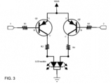
- the first drive circuit includes a first resistor, a second resistor, a third resistor, a fourth resistor, a first triode, and a second triode.
- the first resistor is connected to a first interface of the first controller and a base electrode of the first triode, an emitter electrode of the first triode is connected to an emitter electrode of the second triode, and a collector electrode of the first triode is connected to the second resistor;
- the third resistor is connected to a second interface of the first controller and a base electrode of the second triode, and a collector electrode of the second triode is connected to the fourth resistor; and the second resistor and the fourth resistor are connected to the LED module.
- the gas detector body further includes a second drive circuit, and the first controller is connected to the sensor through the second drive circuit.
- the second drive circuit includes a fifth resistor, a sixth resistor, a seventh resistor, a variable resistor, and a first capacitor.
- the fifth resistor is connected to a third interface of the first controller, an end of the first capacitor, the sixth resistor, and the variable resistor; another end of the first capacitor is grounded; the sixth resistor is connected to the seventh resistor; the seventh resistor is connected to the variable resistor; and the variable resistor is connected to the sensor.
- the gas detector body further includes a third drive circuit and a voice broadcasting device configured to perform voice broadcasting when the leakage gas is detected, and the first controller is connected to the voice broadcasting device through the third drive circuit.
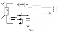
- the third drive circuit includes a second controller, a second capacitor, a third capacitor, a fourth capacitor, a first diode, and a second diode.
- the second controller is connected to a fourth interface of the first controller, a fifth interface of the first controller, a sixth interface of the first controller, an end of the second capacitor, the voice broadcasting device, an end of the fourth capacitor, an end of the first diode, and an end of the third capacitor; another end of the second capacitor is grounded; another end of the fourth capacitor is connected to the voice broadcasting device; the first diode is connected to the second diode; and another end of the third capacitor is grounded.
- the gas detector body further includes a fourth drive circuit and a motor configured to perform vibration reminding when the leakage gas is detected, and the first controller is connected to the motor through the fourth drive circuit.
- the fourth drive circuit includes a ninth resistor, a tenth resistor, and a field effect transistor.
- the ninth resistor is connected to a seventh interface of the first controller, the tenth resistor, and a gate electrode of the field effect transistor; the tenth resistor is connected to a source electrode of the field effect transistor; and a drain electrode of the field effect transistor is connected to the motor.
- the gas detector provided by the embodiments of the disclosure uses a protruding portion of the universal shaped tube as the detection probe, and adds the alarm lamp and the lighting device within the detection probe. Therefore, the gas detector can not only provide an alarm indication, but also can be used as a searchlight to illuminate the area with poor lighting in the gas pipeline when it is not used for the alarm indication. Furthermore, the gas detector can search for the gas pipeline and accurately position the leaked gas pipeline, thereby solving the problem of inconvenient operation in the area with poor lighting in the related art.
- a protruding portion of a universal shaped tube is used as a detection probe, and an alarm lamp and a lighting device are disposed in the detection probe. Therefore, the gas detector can not only provide an alarm indication, but also can be used as a searchlight to illuminate an area with poor lighting in a gas pipeline and to search for the gas pipeline when it is not used for the alarm indication. Furthermore, the gas detector is conductive to accurate search and positioning of a leaked gas pipeline.
- the gas detector includes a gas detector body; the gas detector body includes a button 130, which is used for turning on or turning off the lighting device (i.e., the lighting device is turned on or turned off under an instruction of the button 130), a display screen 120, a detection probe 150, a gas detector housing 110, and a universal shaped tube 140.
- the button 130 and the display screen 120 are disposed on an outer surface of the gas detector housing 110, an end of the universal shaped tube 140 is connected to the gas detector housing 110, and the other end of the universal shaped tube 140 is connected to the detection probe 150.
- the detection probe 150 is internally integrated with a sensor configured to detect a leakage gas, an alarm lamp configured to indicate an alarm when the leakage gas is detected, and a lighting device configured to illuminate (i.e., the universal shaped tube 140, the sensor, the alarm lamp, and the lighting device are integrated as a whole to form the detection probe 150).
- the gas detector body further includes a universal serial bus (USB) interface 160.
- USB universal serial bus
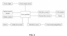
- the gas detector body further includes a power supply, a power switch circuit, a first controller, a first drive circuit, a light-emitting diode (LED) module, a second drive circuit, a sensor, a third drive circuit, a voice broadcasting device, a fourth drive circuit, a motor, a display screen, and a button control circuit.
- the power supply is connected with the power switch circuit; and the first controller is connected with the power switch circuit, the first drive circuit, the second drive circuit, the third drive circuit, the fourth drive circuit, the display screen, and the button control circuit, individually.
- the first drive circuit is connected with the LED module; the second drive circuit is connected with the sensor; the third drive circuit is connected with the voice broadcasting device; and the fourth drive circuit is connected with the motor.
- the power supply may be a lithium battery.
- the power switch circuit can be an existing power switch circuit.
- the first controller can be a chip with model STM32F030C8T6.
- the first drive circuit includes a first resistor R1, a second resistor R2, a third resistor R3, a fourth resistor R4, a first triode Q1, and a second triode Q2.
- the first resistor R1 is connected to a first interface 1 of the first controller and a base electrode B of the first triode Q1, an emitter electrode E of the first triode Q1 is connected to an emitter electrode E of the second triode Q2, and a collector electrode C of the first triode Q1 is connected to the second resistor R2;
- the third resistor R3 is connected to a second interface 2 of the first controller and a base electrode B of the second triode Q2, and a collector electrode C of the second triode Q2 is connected to the fourth resistor R4; and the second resistor R2 and the fourth resistor R4 are connected to the LED module.
- the LED module includes the alarm lamp and the lighting device.
- the sensor On the basis of the first drive circuit, when the sensor detects that there is the leakage gas, the sensor outputs signals to the first controller, and when a concentration of the leakage gas reaches a set value, it is displayed in real time through the display screen 120, i.e., the display screen 120 display the concentration of the leakage gas in real time.
- a pin corresponding to the first interface 1 of the first controller and a pin corresponding to the second interface 2 of the first controller are changed from a high level to a low level, and then the two pins are respectively communicated with the first resistor R1 and the third resistor R3, thereby respectively driving the first triode Q1 and the second triode Q2 to be turned on, and turning on the LED module with double color of red and white.
- the LED module with double color of red and white flashes in red i.e., the alarm lamp flashes in red
- the LED module can be controlled to be turned on in white (i.e., the lighting device illuminates in white) as a flashlight searchlight through the button 130.
- the LED module can be an existing module.
- the second drive circuit includes a fifth resistor R5, a sixth resistor R6, a seventh resistor R7, a variable resistor R8, and a first capacitor C1.
- the fifth resistor R5 is connected to a third interface 3 of the first controller, an end of the first capacitor C1, the sixth resistor R6, and the variable resistor R8; the other end of the first capacitor C1 is grounded; the sixth resistor R6 is connected to the seventh resistor R7; the seventh resistor R7 is connected to the variable resistor R8; and the variable resistor R8 is connected to the sensor.
- the senor may be an existing sensor.
- the third drive circuit includes a second controller U1, a second capacitor C2, a third capacitor C3, a fourth capacitor C4, a first diode D1, and a second diode D2.
- the second controller U1 is connected to a fourth interface 4 of the first controller, a fifth interface 5 of the first controller, a sixth interface 6 of the first controller, an end of the second capacitor C2, the voice broadcasting device SP, an end of the fourth capacitor C4, an end of the first diode D1, and an end of the third capacitor C3; the other end of the second capacitor C2 is grounded; the other end of the fourth capacitor C4 is connected to the voice broadcasting device SP; the first diode D1 is connected to the second diode D2; the second diode D2 is connected to the power supply (i.e., a lithium battery); for example, an arrow shown in FIG. 5 illustrates the connection between the power supply and the second diode D2; and the other end of the third capacitor C3 is grounded.
- the power supply i.e.,
- a pin corresponding to the fourth interface 4 of the first controller, a pin corresponding to the fifth interface 5 of the first controller, and a pin corresponding to the sixth interface 6 of the first controller are communicated with the second controller U1 stored with preset voice, thereby realizing voice broadcast and voice alarm.
- the second controller U1 can be a chip with model SC8120B.
- the voice broadcasting device SP can be a speaker.
- the fourth drive circuit includes a ninth resistor R9, a tenth resistor R10, and a field effect transistor Q3.
- the ninth resistor R9 is connected to a seventh interface 7 of the first controller, the tenth resistor R10, and a gate electrode G of the field effect transistor Q3; the tenth resistor R10 is connected to a source electrode S of the field effect transistor Q3; the source electrode S of the field effect transistor Q3 is grounded; and a drain electrode D of the field effect transistor Q3 is connected to the motor.
- the motor can be connected to the power supply (i.e., VM33) through an eleventh resistor R11.
- a pin corresponding to the seventh interface 7 of the first controller outputs a high level, and the gas detector body is driven by vibrating the motor therein through the ninth resistor R9 and the tenth resistor R10, thereby achieving the vibration alarm.
- the motor can be an existing motor.
- the first resistor R1 is 1.2K ohms (also referred to 1,200 ohms); and for example, the third resistor R3 is 1.2K ohms, etc.
- the extending portion of the universal shaped tube 140 is used as the detection probe 150, and the alarm lamp and the lighting device are added within the detection probe 150, thereby realizing the alarm indication, and realizing the illumination as the searchlight in the area with poor lighting of the gas pipeline during non-alarm. Furthermore, the gas detector of the disclosure can search and find the gas pipeline, and facilitate accurate search and positioning of the leaked gas pipeline.
- the gas detector can also supply power through a large-capacity lithium battery, thereby providing a longer standby test time, and providing functions such as voice broadcasting and voice alarming.
- first and second are used for descriptive purposes only and cannot be understood as indicating or implying relative importance or implicitly indicating the number of indicated technical features. Thus, the features defined with “first” and “second” may explicitly or implicitly include one or more of the features. In the description of the disclosure, “a plurality of” means two or more, unless specifically defined otherwise.
- connection may be a fixed connection, a detachable connection, or integration; or may be a mechanical connection or an electrical connection; or may be a direct connection or an indirect connection through an intermediate medium; or may be a communication relationship between two elements or an interaction relationship between the two elements.
- connection may be a fixed connection, a detachable connection, or integration; or may be a mechanical connection or an electrical connection; or may be a direct connection or an indirect connection through an intermediate medium; or may be a communication relationship between two elements or an interaction relationship between the two elements.
- the first feature is “on” or “under” the second feature, which may be a direct contact between the first feature and the second feature, or the first feature and the second feature are indirectly in contact with each other through an intermediate medium.
- the first feature is "above”, “on” and “upper” relative to the second feature, which may be that the first feature is directly above or obliquely above the second feature, or merely indicates that a level height of the first feature is higher than that of the second feature.
- the first feature is "below”, “under” and “lower” relative to the second feature, which may be that the first feature is directly below or obliquely below the second feature, or merely indicates that a level height of the first feature level is lower than that of the second feature.
- the terms “an embodiment”, “some embodiments”, “the embodiment”, “an example”, “an illustrated example”, or “some examples” refer to the specific features, structures, materials, or characteristics described in connection with the embodiment or example being included in at least one embodiment or example of the disclosure.
- the schematic representation of the above terms does not necessarily refer to the same embodiment or example.
- the specific features, structures, materials, or characteristics described may be combined in any suitable manner in any one or more embodiments or examples.
- those skilled in the related art may randomly combine the different embodiments or examples described in the specification as well as the features of different embodiments or examples.
Landscapes
- Chemical & Material Sciences (AREA)
- Engineering & Computer Science (AREA)
- Health & Medical Sciences (AREA)
- Physics & Mathematics (AREA)
- General Physics & Mathematics (AREA)
- Life Sciences & Earth Sciences (AREA)
- General Health & Medical Sciences (AREA)
- Combustion & Propulsion (AREA)
- Food Science & Technology (AREA)
- Biochemistry (AREA)
- Medicinal Chemistry (AREA)
- Immunology (AREA)
- Pathology (AREA)
- Analytical Chemistry (AREA)
- Environmental & Geological Engineering (AREA)
- Toxicology (AREA)
- Business, Economics & Management (AREA)
- Emergency Management (AREA)
- Emergency Alarm Devices (AREA)
- Alarm Systems (AREA)
Applications Claiming Priority (1)
| Application Number | Priority Date | Filing Date | Title |
|---|---|---|---|
| CN202222431811.XU CN218546682U (zh) | 2022-09-14 | 2022-09-14 | 一种气体检测仪 |
Publications (3)
| Publication Number | Publication Date |
|---|---|
| EP4339577A1 true EP4339577A1 (de) | 2024-03-20 |
| EP4339577C0 EP4339577C0 (de) | 2025-08-13 |
| EP4339577B1 EP4339577B1 (de) | 2025-08-13 |
Family
ID=85273295
Family Applications (1)
| Application Number | Title | Priority Date | Filing Date |
|---|---|---|---|
| EP23197169.8A Active EP4339577B1 (de) | 2022-09-14 | 2023-09-13 | Gasdetektor |
Country Status (3)
| Country | Link |
|---|---|
| US (1) | US20240085392A1 (de) |
| EP (1) | EP4339577B1 (de) |
| CN (1) | CN218546682U (de) |
Citations (7)
| Publication number | Priority date | Publication date | Assignee | Title |
|---|---|---|---|---|
| CN101403446A (zh) * | 2008-11-19 | 2009-04-08 | 上海宝洋塑业有限公司 | 防漏水智能阀 |
| JP4848034B2 (ja) * | 2004-06-30 | 2011-12-28 | インフィコン ゲゼルシャフト ミット ベシュレンクテル ハフツング | 照明装置を備えるサンプリングゾンデ |
| CN204805994U (zh) * | 2015-05-06 | 2015-11-25 | 比亚迪股份有限公司 | 能够预警危险气体的led灯 |
| WO2017177983A1 (zh) * | 2016-04-15 | 2017-10-19 | 中国科学院过程工程研究所 | 气敏传感器报警电路 |
| EP2951571B1 (de) * | 2013-02-01 | 2019-01-09 | Automotive Test Solutions, Inc. | Leckdetektionsformel, analysevorrichtung und verfahren |
| CN214256484U (zh) * | 2021-02-06 | 2021-09-21 | 肇庆新奥燃气有限公司 | 一种便携式燃气检测装置 |
| CN216211478U (zh) * | 2021-11-10 | 2022-04-05 | 李芳芳 | 燃气泄漏检测装置 |
Family Cites Families (1)
| Publication number | Priority date | Publication date | Assignee | Title |
|---|---|---|---|---|
| US20030079519A1 (en) * | 2001-10-31 | 2003-05-01 | Charles Wilkinson | Apparatus and method for alerting a user of the presence of a target gas |
-
2022
- 2022-09-14 CN CN202222431811.XU patent/CN218546682U/zh active Active
-
2023
- 2023-09-12 US US18/465,176 patent/US20240085392A1/en active Pending
- 2023-09-13 EP EP23197169.8A patent/EP4339577B1/de active Active
Patent Citations (7)
| Publication number | Priority date | Publication date | Assignee | Title |
|---|---|---|---|---|
| JP4848034B2 (ja) * | 2004-06-30 | 2011-12-28 | インフィコン ゲゼルシャフト ミット ベシュレンクテル ハフツング | 照明装置を備えるサンプリングゾンデ |
| CN101403446A (zh) * | 2008-11-19 | 2009-04-08 | 上海宝洋塑业有限公司 | 防漏水智能阀 |
| EP2951571B1 (de) * | 2013-02-01 | 2019-01-09 | Automotive Test Solutions, Inc. | Leckdetektionsformel, analysevorrichtung und verfahren |
| CN204805994U (zh) * | 2015-05-06 | 2015-11-25 | 比亚迪股份有限公司 | 能够预警危险气体的led灯 |
| WO2017177983A1 (zh) * | 2016-04-15 | 2017-10-19 | 中国科学院过程工程研究所 | 气敏传感器报警电路 |
| CN214256484U (zh) * | 2021-02-06 | 2021-09-21 | 肇庆新奥燃气有限公司 | 一种便携式燃气检测装置 |
| CN216211478U (zh) * | 2021-11-10 | 2022-04-05 | 李芳芳 | 燃气泄漏检测装置 |
Also Published As
| Publication number | Publication date |
|---|---|
| US20240085392A1 (en) | 2024-03-14 |
| CN218546682U (zh) | 2023-02-28 |
| EP4339577C0 (de) | 2025-08-13 |
| EP4339577B1 (de) | 2025-08-13 |
Similar Documents
| Publication | Publication Date | Title |
|---|---|---|
| EP4339577A1 (de) | Gasdetektor | |
| CN211454771U (zh) | 一种可防误报的可燃气体泄漏检测电路 | |
| CN204805994U (zh) | 能够预警危险气体的led灯 | |
| CN221352157U (zh) | 一种声光报警器 | |
| CN214795131U (zh) | 一种电池掉电检测电路 | |
| JP2015121946A (ja) | ガス検知システム | |
| CN210863958U (zh) | 一种基于lcd显示的语音播报插座测试仪 | |
| CN212808051U (zh) | 一种便携式激光甲烷检测仪 | |
| CN211426820U (zh) | 一种led显示设备的生产检测设备 | |
| CN210037694U (zh) | 一种防爆气体检测仪用示警装置 | |
| CN216525645U (zh) | 具有灯带的二氧化碳浓度检测仪 | |
| EP3141168A1 (de) | Rührstab für lebensmittelverarbeiter | |
| CN113689804A (zh) | 一种应急逃生指示装置 | |
| CN223346975U (zh) | 充电器自动检测装置及充电器 | |
| CN113058192A (zh) | 一种灭火器检测仪 | |
| CN108389365B (zh) | 地震报警装置 | |
| CN222353979U (zh) | 一种显示模组的电压检测装置 | |
| CN210721802U (zh) | 基于led点阵显示的一氧化碳报警装置 | |
| CN216526161U (zh) | 一种机箱双显线路检测仪 | |
| CN212932864U (zh) | 一种全智能电路板检查装置 | |
| CN206635822U (zh) | 全自动基桩静载仪 | |
| CN217739133U (zh) | 便携式气体探测仪 | |
| CN223499860U (zh) | 一种水位检测装置、制冰机及冰箱 | |
| CN206743547U (zh) | 具有报警功能的阻抗及咪电流检测装置 | |
| CN218629942U (zh) | 一种电能表 |
Legal Events
| Date | Code | Title | Description |
|---|---|---|---|
| PUAI | Public reference made under article 153(3) epc to a published international application that has entered the european phase |
Free format text: ORIGINAL CODE: 0009012 |
|
| STAA | Information on the status of an ep patent application or granted ep patent |
Free format text: STATUS: THE APPLICATION HAS BEEN PUBLISHED |
|
| AK | Designated contracting states |
Kind code of ref document: A1 Designated state(s): AL AT BE BG CH CY CZ DE DK EE ES FI FR GB GR HR HU IE IS IT LI LT LU LV MC ME MK MT NL NO PL PT RO RS SE SI SK SM TR |
|
| STAA | Information on the status of an ep patent application or granted ep patent |
Free format text: STATUS: REQUEST FOR EXAMINATION WAS MADE |
|
| 17P | Request for examination filed |
Effective date: 20240919 |
|
| RBV | Designated contracting states (corrected) |
Designated state(s): AL AT BE BG CH CY CZ DE DK EE ES FI FR GB GR HR HU IE IS IT LI LT LU LV MC ME MK MT NL NO PL PT RO RS SE SI SK SM TR |
|
| STAA | Information on the status of an ep patent application or granted ep patent |
Free format text: STATUS: EXAMINATION IS IN PROGRESS |
|
| 17Q | First examination report despatched |
Effective date: 20241210 |
|
| GRAP | Despatch of communication of intention to grant a patent |
Free format text: ORIGINAL CODE: EPIDOSNIGR1 |
|
| STAA | Information on the status of an ep patent application or granted ep patent |
Free format text: STATUS: GRANT OF PATENT IS INTENDED |
|
| INTG | Intention to grant announced |
Effective date: 20250416 |
|
| GRAS | Grant fee paid |
Free format text: ORIGINAL CODE: EPIDOSNIGR3 |
|
| GRAA | (expected) grant |
Free format text: ORIGINAL CODE: 0009210 |
|
| STAA | Information on the status of an ep patent application or granted ep patent |
Free format text: STATUS: THE PATENT HAS BEEN GRANTED |
|
| AK | Designated contracting states |
Kind code of ref document: B1 Designated state(s): AL AT BE BG CH CY CZ DE DK EE ES FI FR GB GR HR HU IE IS IT LI LT LU LV MC ME MK MT NL NO PL PT RO RS SE SI SK SM TR |
|
| REG | Reference to a national code |
Ref country code: GB Ref legal event code: FG4D |
|
| REG | Reference to a national code |
Ref country code: CH Ref legal event code: EP |
|
| REG | Reference to a national code |
Ref country code: DE Ref legal event code: R096 Ref document number: 602023005661 Country of ref document: DE |
|
| REG | Reference to a national code |
Ref country code: IE Ref legal event code: FG4D |
|
| PGFP | Annual fee paid to national office [announced via postgrant information from national office to epo] |
Ref country code: AT Payment date: 20251020 Year of fee payment: 3 |
|
| U01 | Request for unitary effect filed |
Effective date: 20250912 |
|
| U07 | Unitary effect registered |
Designated state(s): AT BE BG DE DK EE FI FR IT LT LU LV MT NL PT RO SE SI Effective date: 20250918 |
|
| U20 | Renewal fee for the european patent with unitary effect paid |
Year of fee payment: 3 Effective date: 20250922 |
|
| PG25 | Lapsed in a contracting state [announced via postgrant information from national office to epo] |
Ref country code: IS Free format text: LAPSE BECAUSE OF FAILURE TO SUBMIT A TRANSLATION OF THE DESCRIPTION OR TO PAY THE FEE WITHIN THE PRESCRIBED TIME-LIMIT Effective date: 20251213 |
|
| PG25 | Lapsed in a contracting state [announced via postgrant information from national office to epo] |
Ref country code: NO Free format text: LAPSE BECAUSE OF FAILURE TO SUBMIT A TRANSLATION OF THE DESCRIPTION OR TO PAY THE FEE WITHIN THE PRESCRIBED TIME-LIMIT Effective date: 20251113 |
|
| PG25 | Lapsed in a contracting state [announced via postgrant information from national office to epo] |
Ref country code: HR Free format text: LAPSE BECAUSE OF FAILURE TO SUBMIT A TRANSLATION OF THE DESCRIPTION OR TO PAY THE FEE WITHIN THE PRESCRIBED TIME-LIMIT Effective date: 20250813 |
|
| PG25 | Lapsed in a contracting state [announced via postgrant information from national office to epo] |
Ref country code: GR Free format text: LAPSE BECAUSE OF FAILURE TO SUBMIT A TRANSLATION OF THE DESCRIPTION OR TO PAY THE FEE WITHIN THE PRESCRIBED TIME-LIMIT Effective date: 20251114 |
|
| PG25 | Lapsed in a contracting state [announced via postgrant information from national office to epo] |
Ref country code: PL Free format text: LAPSE BECAUSE OF FAILURE TO SUBMIT A TRANSLATION OF THE DESCRIPTION OR TO PAY THE FEE WITHIN THE PRESCRIBED TIME-LIMIT Effective date: 20250813 |
|
| PG25 | Lapsed in a contracting state [announced via postgrant information from national office to epo] |
Ref country code: RS Free format text: LAPSE BECAUSE OF FAILURE TO SUBMIT A TRANSLATION OF THE DESCRIPTION OR TO PAY THE FEE WITHIN THE PRESCRIBED TIME-LIMIT Effective date: 20251113 |
|
| PG25 | Lapsed in a contracting state [announced via postgrant information from national office to epo] |
Ref country code: ES Free format text: LAPSE BECAUSE OF FAILURE TO SUBMIT A TRANSLATION OF THE DESCRIPTION OR TO PAY THE FEE WITHIN THE PRESCRIBED TIME-LIMIT Effective date: 20250813 |
|
| PG25 | Lapsed in a contracting state [announced via postgrant information from national office to epo] |
Ref country code: SM Free format text: LAPSE BECAUSE OF FAILURE TO SUBMIT A TRANSLATION OF THE DESCRIPTION OR TO PAY THE FEE WITHIN THE PRESCRIBED TIME-LIMIT Effective date: 20250813 |
|
| PG25 | Lapsed in a contracting state [announced via postgrant information from national office to epo] |
Ref country code: CZ Free format text: LAPSE BECAUSE OF FAILURE TO SUBMIT A TRANSLATION OF THE DESCRIPTION OR TO PAY THE FEE WITHIN THE PRESCRIBED TIME-LIMIT Effective date: 20250813 |
|
| PG25 | Lapsed in a contracting state [announced via postgrant information from national office to epo] |
Ref country code: SK Free format text: LAPSE BECAUSE OF FAILURE TO SUBMIT A TRANSLATION OF THE DESCRIPTION OR TO PAY THE FEE WITHIN THE PRESCRIBED TIME-LIMIT Effective date: 20250813 |