EP4339622B1 - Capteur et dispositif électronique - Google Patents
Capteur et dispositif électronique Download PDFInfo
- Publication number
- EP4339622B1 EP4339622B1 EP23156529.2A EP23156529A EP4339622B1 EP 4339622 B1 EP4339622 B1 EP 4339622B1 EP 23156529 A EP23156529 A EP 23156529A EP 4339622 B1 EP4339622 B1 EP 4339622B1
- Authority
- EP
- European Patent Office
- Prior art keywords
- counter
- electrode
- condition
- beam electrode
- support
- Prior art date
- Legal status (The legal status is an assumption and is not a legal conclusion. Google has not performed a legal analysis and makes no representation as to the accuracy of the status listed.)
- Active
Links
Images


Classifications
-
- G—PHYSICS
- G01—MEASURING; TESTING
- G01P—MEASURING LINEAR OR ANGULAR SPEED, ACCELERATION, DECELERATION, OR SHOCK; INDICATING PRESENCE, ABSENCE, OR DIRECTION, OF MOVEMENT
- G01P15/00—Measuring acceleration; Measuring deceleration; Measuring shock, i.e. sudden change of acceleration
- G01P15/02—Measuring acceleration; Measuring deceleration; Measuring shock, i.e. sudden change of acceleration by making use of inertia forces using solid seismic masses
- G01P15/08—Measuring acceleration; Measuring deceleration; Measuring shock, i.e. sudden change of acceleration by making use of inertia forces using solid seismic masses with conversion into electric or magnetic values
- G01P15/097—Measuring acceleration; Measuring deceleration; Measuring shock, i.e. sudden change of acceleration by making use of inertia forces using solid seismic masses with conversion into electric or magnetic values by vibratory elements
-
- G—PHYSICS
- G01—MEASURING; TESTING
- G01C—MEASURING DISTANCES, LEVELS OR BEARINGS; SURVEYING; NAVIGATION; GYROSCOPIC INSTRUMENTS; PHOTOGRAMMETRY OR VIDEOGRAMMETRY
- G01C19/00—Gyroscopes; Turn-sensitive devices using vibrating masses; Turn-sensitive devices without moving masses; Measuring angular rate using gyroscopic effects
- G01C19/56—Turn-sensitive devices using vibrating masses, e.g. vibratory angular rate sensors based on Coriolis forces
- G01C19/5642—Turn-sensitive devices using vibrating masses, e.g. vibratory angular rate sensors based on Coriolis forces using vibrating bars or beams
- G01C19/5656—Turn-sensitive devices using vibrating masses, e.g. vibratory angular rate sensors based on Coriolis forces using vibrating bars or beams the devices involving a micromechanical structure
-
- G—PHYSICS
- G01—MEASURING; TESTING
- G01C—MEASURING DISTANCES, LEVELS OR BEARINGS; SURVEYING; NAVIGATION; GYROSCOPIC INSTRUMENTS; PHOTOGRAMMETRY OR VIDEOGRAMMETRY
- G01C19/00—Gyroscopes; Turn-sensitive devices using vibrating masses; Turn-sensitive devices without moving masses; Measuring angular rate using gyroscopic effects
- G01C19/56—Turn-sensitive devices using vibrating masses, e.g. vibratory angular rate sensors based on Coriolis forces
- G01C19/5642—Turn-sensitive devices using vibrating masses, e.g. vibratory angular rate sensors based on Coriolis forces using vibrating bars or beams
- G01C19/5663—Manufacturing; Trimming; Mounting; Housings
-
- G—PHYSICS
- G01—MEASURING; TESTING
- G01P—MEASURING LINEAR OR ANGULAR SPEED, ACCELERATION, DECELERATION, OR SHOCK; INDICATING PRESENCE, ABSENCE, OR DIRECTION, OF MOVEMENT
- G01P15/00—Measuring acceleration; Measuring deceleration; Measuring shock, i.e. sudden change of acceleration
- G01P15/02—Measuring acceleration; Measuring deceleration; Measuring shock, i.e. sudden change of acceleration by making use of inertia forces using solid seismic masses
- G01P15/08—Measuring acceleration; Measuring deceleration; Measuring shock, i.e. sudden change of acceleration by making use of inertia forces using solid seismic masses with conversion into electric or magnetic values
- G01P15/0802—Details
Definitions
- Embodiments described herein relate generally to a sensor and an electronic device.
- US2012286886 A1 describes a resonator for a sensor, e.g. an accelerometer, comprising a base, a support portion, a first connection structure, a second connection structure, a first beam representing a first beam electrode, and a second beam representing a second beam electrode.
- the electrodes are designed in the shape of fingers. The finger width can be altered to adjust the resonant frequency.
- a sensor includes a base, a first support portion fixed to the substrate, and a first member supported by the first support portion.
- a gap is provided between the base and the first member.
- the first member includes a first support region, a first connection structure, a second connection structure, a first beam, a second beam, a first beam electrode, and a second beam electrode.
- the first support portion is provided between the base and the first support region in a first direction from the base to the first support portion.
- the first support region is supported by the first support portion.
- the first beam and the second beam extend along a second direction crossing the first direction.
- a direction from the first connection structure to the second connection structure is along the second direction.
- the first support region is provided between the first connection structure and the second connection structure in the second direction.
- the first beam includes a first end and a first other end.
- the first end is connected to the first connection structure.
- the first other end is connected to the first support region.
- the second beam includes a second end and a second end.
- the second end is connected to the second connection structure.
- the second end is connected to the first support region.
- the first beam electrode is connected to the first beam.
- a third direction from the first beam to the first beam electrode crosses a plane including the first direction and the second direction.
- the second beam electrode is connected to the second beam.
- a direction from the second beam to the second beam electrode is along the third direction.
- the first beam electrode and the second beam electrode satisfy at least one of a first condition, a second condition, a third condition, a fourth condition, a fifth condition, a sixth condition, a seventh condition, or an eighth condition.
- a second mass of the second beam electrode is different from a first mass of the first beam electrode.
- a second thickness along the first direction of the second beam electrode is different from a first thickness along the first direction of the first beam electrode.
- at least a part of the second material included in the second beam electrode is different from at least a part of the first material included in the first beam electrode.
- a second size of a second hole included in the second beam electrode is different from a first size of a first hole included in the first beam electrode.
- a second density of the second hole is different from a first density of the first hole.
- a second number of the second holes is different from a first number of the first holes.
- a second shape of the second hole is different from a first shape of the first hole.
- a second layer configuration of the second beam electrode is different from a first layer configuration of the first beam electrode.
- FIG. 1 is a schematic plan view illustrating a sensor according to a first embodiment.
- FIG. 2 is a schematic cross-sectional view illustrating the sensor according to the first embodiment.
- FIG. 2 is a cross-sectional view taken along the line A1-A2 of FIG. 1 .
- the first support portion 10S is fixed to the base 50S.
- the first member 10M is supported by the first support portion 10S.
- a gap g1 is provided between the base 50S and the first member 10M. At least part of the first member 10M may be conductive.
- a first direction D1 from the base 50S to the first support portion 10S is defined as a Z-axis direction.
- One direction perpendicular to the Z-axis direction is defined as the X-axis direction.
- a direction perpendicular to the Z-axis direction and the X-axis direction is defined as the Y-axis direction.
- the first member 10M includes a first support region 10Ms, a first movable region 10Ma, a second movable region 10Mb, a first connection structure 21c, a second connection structure 22c, a first beam 31, a second beam 32, a first beam electrode 31E, and a second beam electrode 32E.
- the first support portion 10S is provided between the base 50S and the first support region 10Ms in the first direction D1.
- the first beam 31 and the second beam 32 extend along a second direction D2.
- the second direction D2 crosses the first direction D1.
- the second direction D2 is, for example, the X-axis direction.
- the first support region 10Ms is provided between the first movable region 10Ma and the second movable region 10Mb.
- the first beam 31 includes a first end 31e and a first other end 31f.
- the first end 31e is connected to the first connection structure 21c.
- the first other end 31f is connected to the first support region 10Ms.
- the second connection structure 22c is supported by the second movable region 10Mb.
- the second connection structure 22c is provided between the first support region 10Ms and the second movable region 10Mb in the second direction D2.
- the second beam 32 includes a second end 32e and a second other end 32f.
- the second end 32e is connected to the second connection structure 22c.
- the second other end 32f is connected to the first support region 10Ms.
- the first beam electrode 31E is connected to the first beam 31.
- a third direction D3 from the first beam 31 to the first beam electrode 31E crosses a plane including the first direction D1 and the second direction D2.
- the second beam electrode 32E is connected to the second beam 32.
- the direction from the second beam 32 to the second beam electrode 32E is along the third direction D3.
- the second beam electrode 32E is asymmetric with respect to the first beam electrode 31E.
- at least one of mass, thickness, shape, layer configuration, material, and holes is different between the first beam electrode 31E and the second beam electrode 32E.
- a difference in resonance frequency occurs between the first beam 31 and the second beam 32 . This increases the dynamic range of the detection.
- a sensor capable of improving characteristics can be provided.
- FIG. 3 is a schematic plan view illustrating a part of the sensor according to the first embodiment.
- FIG. 3 A part of FIG. 1 is shown enlarged in FIG. 3 .
- the senor 110 may include a first electrode 51 and a second electrode 52.
- the first electrode 51 and the second electrode 52 are fixed to the base 50S.
- the first member 10M includes the first beam electrode 31E and the second beam electrode 32E.
- the first electrode 51 faces the first beam electrode 31E.
- the second electrode 52 faces the second beam electrode 32E.
- the controller 70 is electrically connected to the first electrode 51, the second electrode 52, the first beam electrode 31E and the second beam electrode 32E.
- the first beam electrode 31E and the second beam electrode 32E are electrically connected to, for example, the first support region 10Ms of the first member 10M.
- the controller 70 is configured to apply a drive signal including an AC component between the first electrode 51 and the first beam electrode 31E.
- the controller 70 is configured to apply the drive signal including the AC component between the second electrode 52 and the second beam electrode 32E.
- the first beam 31 can vibrate according to the drive signal.
- the second beam 32 can vibrate according to the drive signal.
- the first member 10M when force (acceleration) is applied to the first member 10M from the outside, the first member 10M can be displaced along the second direction D2.
- the first movable region 10Ma and the second movable region 10Mb are displaced along the second direction D2.
- the displacement is transmitted to the first connection structure 21c and the second connection structure 22c.
- the first connection structure 21c and the second connection structure 22c are displaced along the second direction D2.
- Compressive stress or tensile stress is applied to the first beam 31 and the second beam 32 based on this displacement.
- the stress changes the resonance frequency of the first beam 31 and the resonance frequency of the second beam 32 .
- the magnitude of change in resonance frequency is opposite between the first beam 31 and the second beam 32.
- the first beam electrode 31E and the second beam electrode 32E are asymmetrical with each other. This causes a difference in resonance frequency between the first beam 31 and the second beam 32. This increases the dynamic range of detection.
- the difference in resonance frequencies between the first beam 31 and the second beam 32 may be detected by any method.
- an optical technique may be used to detect the difference in resonance frequencies.
- an electrical method may be used to detect the difference in resonant frequencies. An example of a configuration in which the difference in resonance frequencies is detected by an electrical method will be described below.
- the sensor 110 may include a first counter electrode 51A and a second counter electrode 52A.
- the first counter electrode 51A and the second counter electrode 52A are fixed to the base 50S.
- the first member 10M may include a first counter beam electrode 31AE and a second counter beam electrode 32AE.
- the first counter beam electrode 31AE is connected to the first beam 31.
- the first beam 31 is provided between the first counter beam electrode 31AE and the first beam electrode 31E.
- the second counter beam electrode 32AE is connected to the second beam 32.
- the second beam 32 is provided between the second counter beam electrode 32AE and the second beam electrode 32E.
- the first electrode 51 faces the first beam electrode 31E.
- the first counter electrode 51A faces the first counter beam electrode 31AE.
- the second electrode 52 faces the second beam electrode 32E.
- the second counter electrode 52A faces the second counter beam electrode 32AE.
- the controller 70 is configured to apply the drive signal including the AC component between the first electrode 51 and the first beam electrode 31E.
- the controller 70 is configured to detect an electrical signal generated between the first counter electrode 51A and the first counter beam electrode 31AE.
- the controller 70 is configured to apply the drive signal including the AC component between the second electrode 52 and the second beam electrode 32E.
- the controller 70 is configured to detect the electrical signal generated between the second counter electrode 52A and the second counter beam electrode 32AE.
- the second counter beam electrode 32AE may be asymmetric with respect to the first counter beam electrode 31AE.
- at least one of mass, thickness, shape, layer configuration, material, and hole is different between the first counter beam electrode 31AE and the second counter beam electrode 32AE.
- the difference in resonance frequencies between the first beam 31 and the second beam 32 increases. This increases the dynamic range of detection.
- FIG. 4A and FIG. 4B are schematic cross-sectional views illustrating a part of the sensor according to the first embodiment.
- FIG. 4A is a cross-sectional view taken along the line B1-B2 in FIG. 1 .
- FIG. 4B is a cross-sectional view taken along the line C1-C2 of FIG. 1 .
- the first beam electrode 31E includes a first hole 31h.
- the second beam electrode 32E includes a second hole 32h.
- the number of second holes 32h is different from the number of first holes 31h.
- the second density of the second holes 32h is different from the first density of the first holes 31h.
- the first counter beam electrode 31AE includes a first counter hole 31Ah.
- the second counter beam electrode 32AE includes a second counter hole 32Ah.
- the number of second counter holes 32Ah is different from the number of first counter holes 31Ah.
- the second counter density of the second counter holes 32Ah is different from the first counter density of the first counter holes 31Ah.
- FIG. 5A and FIG. 5B are schematic cross-sectional views illustrating parts of a sensor according to the first embodiment.
- the first counter beam electrode 31AE includes the first counter hole 31Ah.
- the second counter beam electrode 32AE includes the second counter hole 32Ah.
- the size of the second counter hole 32Ah in this example, the length along the second direction D2 is different from the size of the first counter hole 31Ah (in this example, the length along the second direction D2).
- the second counter size of the second counter hole 32Ah is different from the first counter size of the first counter hole 31Ah.
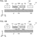
- FIG. 6A and FIG. 6B are schematic cross-sectional views illustrating parts of a sensor according to the first embodiment.
- FIG. 6A is a cross-sectional view corresponding to the line B1-B2 line in FIG. 1 .
- FIG. 6B is a cross-sectional view corresponding to the line C1-C2 in FIG. 1 .
- the thickness of the first beam electrode 31E is different from the thickness of the second beam electrode 32E.
- the second thickness along the first direction D1 of the second beam electrode 32E is different from the first thickness along the first direction D1 of the first beam electrode 31E.
- the thickness of the first counter beam electrode 31AE is different from the thickness of the second counter beam electrode 32AE.
- the second counter thickness along the first direction D1 of the second counter beam electrode 32AE is different from the first counter thickness along the first direction D1 of the first counter beam electrode 31AE.
- FIG. 7A and FIG. 7B are schematic cross-sectional views illustrating parts of a sensor according to the first embodiment.
- FIG. 7A is a cross-sectional view corresponding to the line B1-B2 in FIG. 1 .
- FIG. 7B is a cross-sectional view corresponding to the line C1-C2 in FIG. 1 .
- the second beam electrode 32E includes a metal layer 32F.
- the first beam electrode 31E does not include the metal layer 32F.
- at least a part of the second material included in the second beam electrode 32E is different from at least a part of the first material included in the first beam electrode 31E.
- the second counter beam electrode 32AE includes the metal layer 32F.
- the first counter beam electrode 31AE does not include the metal layer 32F.
- at least a part of the second counter material included in the second counter beam electrode 32AE is different from at least a part of the first counter material included in the first counter beam electrode 31AE.
- first beam electrode 31E and the second beam electrode 32E may have different masses.
- the first beam electrode 31E and the second beam electrode 32E may satisfy at least one of the following a first condition, a second condition, a third condition, a fourth condition, a fifth condition, a sixth condition, a seventh condition, or an eighth condition.
- the second mass of the second beam electrode 32E is different from the first mass of the first beam electrode 31E.
- the second thickness along the first direction D1 of the second beam electrode 32E is different from the first thickness along the first direction D1 of the first beam electrode 31E.
- at least a part of the second material included in the second beam electrode 32E is different from at least a part of the first material included in the first beam electrode 31E.
- the second size of the second hole 32h included in the second beam electrode 32E is different from the first size of the first hole 31h included in the first beam electrode 31E.
- the second density of the second holes 32h is different from the first density of the first holes 31h.
- the second number of second holes 32h is different from the first number of first holes 31h.
- the second shape of the second hole 32h is different from the first shape of the first hole 31h.
- the second layer configuration of the second beam electrode 32E is different from the first layer configuration of the first beam electrode 31E.
- the first counter beam electrode 31AE and the second counter beam electrode 32AE may satisfy at least one of a ninth condition, a tenth condition, an eleventh condition, a twelfth condition, a thirteenth condition, a fourteenth condition, a fifteenth condition or a sixth condition.
- the second counter mass of the second counter beam electrode 32AE is different from the first counter mass of the first counter beam electrode 31AE.
- the second counter thickness along the first direction D1 of the second counter beam electrode 32AE is different from the first counter thickness along the first direction D1 of the first counter beam electrode 31AE.
- at least a part of the second counter material included in the second counter beam electrode 32AE is different from at least a part of the first counter material included in the first counter beam electrode 31AE.
- the second counter size of the second counter hole 32Ah included in the second counter beam electrode 32AE is different from the first counter size of the first counter hole 31Ah included in the first counter beam electrode 31AE.
- the second counter density of the second counter holes 32Ah is different from the first counter density of the first counter holes 31Ah.
- the second counter number of the second counter holes 32Ah is different from the first counter number of the first counter holes 31Ah.
- the second counter shape of the second counter hole 32Ah is different from the first counter shape of the first counter hole 31Ah.
- the second counter layer configuration of the second counter beam electrode 32AE is different from the first counter layer configuration of the first counter beam electrode 31AE.
- the planar outline of the first beam electrode 31E may be the same as the planar outline of the second beam electrode 32E.
- the planar outline of the first counter beam electrode 31AE may be the same as the planar outline of the second counter beam electrode 32AE.
- the same heat dissipation is obtained.
- the temperature difference between the first beam electrode 31E and the second beam electrode 32E can be suppressed.
- the temperature difference between the first counter beam electrode 31AE and the second counter beam electrode 32AE can be suppressed.
- the first outline of the first planar shape of the first beam electrode 31E in the first plane (X-Y plane) including the second direction D2 and the third direction D3 is substantially the same as the second outline of the second planar shape of the second beam electrode 32E in the first plane.
- the first counter beam electrode 31AE is preferably linearly symmetrical with the first beam electrode 31E with respect to an axis passing through the first connection structure 21c and the second connection structure 22c and along the second direction D2.
- the second counter beam electrode 32AE is preferably linearly symmetrical with the second beam electrode 32E with respect to the axis passing through the first connection structure 21c and the second connection structure 22c and along the second direction D2. Stable vibration is obtained.
- the first member 10M may further include a first structure 21 and a first support structure 11S.
- the first structure position in the second direction D2 of the first structure 21 is located between the first movable region position in the second direction D2 of the first movable region 10Ma and the first beam position in the second direction D2 of the first beam 31.
- the first connection structure position in the second direction D2 of the first connection structure 21c is located between the first structure position and the first beam position.
- the first support structure position in the second direction D2 of the first support structure 11S is located between the first structure position and the first support region position in the second direction D2 of the first support region 10Ms.
- the first structure 21 includes a first portion 21e, a first other portion 21f and a first intermediate portion 21m. A direction from the first portion 21e to the first other portion 21f is along the third direction D3.
- the first intermediate portion 21m is provided between the first portion 21e and the first other portion 21f.
- the first portion 21e is connected to the first connection structure 21c.
- the first other portion 21f is connected to the first movable region 10Ma.
- the first intermediate portion 21m is connected to the first support structure 11S.
- the first member 10M may further include a third structure 23 and a third support structure 13S.
- the third structure position in the second direction D2 of the third structure 23 is located between the second beam position in the second direction D2 of the second beam 32 and the second movable region position in the second direction D2 of the second movable region 10Mb.
- the second connection structure position in the second direction D2 of the second connection structure 22c is located between the second beam position and the third structure position.
- the third support structure position in the second direction D2 of the third support structure 13S is located between the first support region position and the third structure position.
- the third structure 23 includes a third portion 23e, a third other portion 23f and a third intermediate portion 23m. A direction from the third portion 23e to the third other portion 23f is along the third direction D3.
- the third intermediate portion 23m is provided between the third portion 23e and the third other portion 23f.
- the third portion 23e is connected to the second connection structure 22c.
- the third other portion 23f is connected to the second movable region 10Mb.
- the third intermediate portion 23m is connected to the third support structure 13S.
- the first member 10M may further include a second structure 22 and a second support structure 12S.
- the second structure position in the second direction D2 of the second structure 22 is located between the first movable region position and the first beam position.
- the second support structure position in the second direction D2 of the second support structure 12S is located between the second structure position and the first support region position.
- the second structure 22 includes a second portion 22e, a second other portion 22f and a second intermediate portion 22m.
- a direction from the second other portion 22f to the second portion 22e is along the third direction D3.
- the second intermediate portion 22m is provided between the second other portion 22f and the second portion 22e.
- the second portion 22e is connected to the first connection structure 21c.
- the second other portion 22f is connected to the first movable region 10Ma.
- the second intermediate portion 22m is connected to the second support structure 12S.
- the first connection structure 21c is provided between at least a part of the second support structure 12S and at least a part of the first support structure 11S.
- the first member 10M may further include a fourth structure 24 and a fourth support structure 14S.
- a fourth structure position in the second direction D2 of the fourth structure 24 is located between the second beam position and the second movable region position.
- a fourth support structure position in the second direction D2 of the fourth support structure 14S is located between the first support region position and the fourth structure position.
- the fourth structure 24 includes a fourth portion 24e, a fourth other portion 24f and a fourth intermediate portion 24m.
- a direction from the fourth other portion 24f to the fourth portion 24e is along the third direction D3.
- the fourth intermediate portion 24m is provided between the fourth other portion 24f and the fourth portion 24e.
- the fourth portion 24e is connected to the second connection structure 22c.
- the fourth other portion 24f is connected to the second movable region 10Mb.
- the fourth intermediate portion 24m is connected to the fourth support structure 14S.
- the second connection structure 22c is provided between at least a part of the fourth support structure 14S and at least a part of the third support structure 13S.
- the first structure 21, the second structure 22, the third structure 23 and the fourth structure 24 are, for example, levers.
- the first portion 21e is, for example, an action point.
- the first other portion 21f is, for example, the point of effort.
- the first intermediate portion 21m is, for example, a fulcrum.
- the second portion 22e is, for example, an action point.
- the second other portion 22f is, for example, a point of effort.
- the second intermediate portion 22m is, for example, a fulcrum.
- the third portion 23e is, for example, an action point.
- the third other portion 23f is, for example, a point of effort.
- the third intermediate portion 23m is, for example, a fulcrum.
- the fourth portion 24e is, for example, an action point.
- the fourth other portion 24f is, for example, the point of effort.
- the fourth intermediate portion 24m is, for example, a fulcrum.
- the displacement of the first movable region 10Ma is efficiently transmitted to the first connection structure 21c by the first structure 21 and the second structure 22.
- the displacement of the second movable region 10Mb is efficiently transmitted to the second connection structure 22c by the third structure 23 and the fourth structure 24.
- a distance along the third direction D3 between the first portion 21e and the first intermediate portion 21m is defined as a first distance.
- a distance along the third direction D3 between the first intermediate portion 21m and the first other portion 21f is defined as a second distance.
- the first distance is shorter than the second distance.
- the first member 10M may include a third movable region 10Mc and a fourth movable region 10Md.
- a direction from the fourth movable region 10Md to the third movable region 10Mc is along the third direction D3.
- the third movable region 10Mc and the fourth movable region 10Md are continuous with the first movable region 10Ma and the second movable region 10Mb.
- the first support region 10Ms is provided between the third movable region 10Mc and the fourth movable region 10Md.
- the first member 10M may further include a first movable region connecting portion 11A.
- a position of the first support structure 11S in the third direction D3 is located between the position of the first support region 10Ms in the third direction D3 and the position of the third movable region 10Mc in the third direction D3.
- the first movable region connecting portion 11A connects the first support structure 11S to the third movable region 10Mc. Displacement along the third direction D3 of the first support structure 11S is suppressed by providing the first movable region connecting portion 11A. The displacement along the second direction D2 of the first support structure 11S becomes stable.
- the first member 10M may further include a second movable region connecting portion 12A.
- a position of the second support structure 12S in the third direction D3 is located between the position of the fourth movable region 10Md in the third direction D3 and the position of the first support region 10Ms in the third direction D3.
- the second movable region connecting portion 12A connects the second support structure 12S to the fourth movable region 10Md. Displacement along the third direction D3 of the second support structure 12S is suppressed by providing the second movable region connecting portion 12A. The displacement along the second direction D2 of the second support structure 12S becomes stable.
- the first member 10M may further include a third movable region connecting portion 13A.
- a position of the third support structure 13S in the third direction D3 is located between the position of the first support region 10Ms in the third direction D3 and the position of the third movable region 10Mc in the third direction D3.
- the third movable region connecting portion 13A connects the third support structure 13S to the third movable region 10Mc. Displacement along the third direction D3 of the third support structure 13S is suppressed by providing the third movable region connecting portion 13A. The displacement along the second direction D2 of the third support structure 13S becomes stable.
- the first member 10M may further include a fourth movable region connecting portion 14A.
- a position of the fourth support structure 14S in the third direction D3 is located between the position of the fourth movable region 10Md in the third direction D3 and the position of the first support region 10Ms in the third direction D3.
- the fourth movable region connecting portion 14A connects the fourth support structure 14S to the fourth movable region 10Md. Displacement along the third direction D3 of the fourth support structure 14S is suppressed by providing the fourth movable region connecting portion 14A. The displacement along the second direction D2 of the fourth support structure 14S becomes stable.
- sensor 110 may be applied to sensors 111-113.
- the first beam electrode 31E includes a first extending portion 31Ea and a first connecting portion 31Ex.
- the first extending portion 31Ea extends along the second direction D2.
- the first connecting portion 31Ex connects the first extending portion 31Ea to the first beam 31.
- the configuration of the first beam electrode 31E may be applied to the first counter beam electrode 31AE, the second beam electrode 32E, and the second counter beam electrode 32AE.
- FIG. 8 is a schematic plan view illustrating a sensor according to the first embodiment.
- FIG. 9A and FIG. 9B are schematic plan views illustrating the sensor according to the first embodiment.
- FIG. 9A and FIG. 9B illustrate a part of FIG. 8 .
- the first beam electrode 31E includes a first extending portion 31Ea extending along the second direction D2 and a first connecting portion 31Ex connecting the first extending portion 31Ea to the first beam 31.
- the first beam electrode 31E includes a plurality of first extending portions 31Ea.
- a plurality of first extending portions 31Ea are provided.
- the first connecting portion 31Ex connects the plurality of first extending portions 31Ea to each other.
- One of the plurality of first extending portions 31Ea is provided between the first beam 31 and another one of the plurality of first extending portions 31Ea.
- the length of the one of the first extending portions 31Ea along the second direction D2 is longer than the length of the other one of the first extending portions 31Ea along the second direction D2.
- the length of the plurality of first extending portions 31Ea along the second direction D2 becomes shorter as leaving from the first beam 31.
- one of the plurality of first extending portions 31Ea may be provided between a part of the first electrode 51 and a part of the first counter electrode 51A.
- the first beam 31 can be vibrated more effectively.
- the resonance frequency of the first beam 31 can be more effectively detected.
- the first counter beam electrode 31AE may include a first counter extending portion 31AEa extending along the second direction D2 and a first counter connecting portion 31AEx connecting the first counter extending portion 31AEa to the first beam 31.
- a plurality of first counter extending portions 31AEa are provided.
- the first counter connecting portion 31AEx connects the plurality of first counter extending portions 31AEa to each other.
- One of the plurality of first counter extending portions 31AEa is provided between the first beam 31 and another one of the plurality of first counter extending portions 31AEa.
- the length of the one of the plurality of first counter extending portions 31AEa along the second direction D2 is longer than the length of another one of the plurality of first counter extending portions 31AEa along the second direction D2.
- the length of the plurality of first counter extending portions 31AEa along the second direction D2 becomes shorter as leaving from the first beam 31.
- the second beam electrode 32E may include a second extending portion 32Ea extending along the second direction D2 and a second connecting portion 32Ex connecting the second extending portion 32Ea to the second beam 32.
- a plurality of second extending portions 32Ea are provided.
- the second connecting portion 32Ex connects the plurality of second extending portions 32Ea to each other.
- One of the plurality of second extending portions 32Ea is provided between the second beam 32 and another one of the plurality of second extending portions 32Ea.
- the length of the one of the plurality of second extending portions 32Ea along the second direction D2 is longer than the length of the other one of the plurality of second extending portions 32Ea along the second direction D2.
- the length of the plurality of second extending portions 32Ea along the second direction D2 becomes shorter as leaving from the second beam 32.
- the second counter beam electrode 32AE may include a second counter extending portion 32AEa extending along the second direction D2 and a second counter connecting portion 32AEx connecting the second counter extending portion 32AEa to the second beam 32.
- a plurality of second counter extending portions 32AEa are provided.
- the second counter connecting portion 32AEx connects the plurality of second counter extending portions 32AEa to each other.
- One of the plurality of second counter extending portions 32AEa is provided between the second beam 32 and another one of the plurality of second counter extending portions 32AEa.
- the length of the one of the plurality of second counter extending portions 32AEa along the second direction D2 is longer than the length of the other one of the plurality of second counter extending portions 32AEa along the second direction D2.
- the length of the plurality of second counter extending portions 32AEa along the second direction D2 becomes shorter as leaving from the second beam 32.
- a wide dynamic range can be obtained in the sensors 111 to 114 as well.
- a sensor capable of improving characteristics can be provided.
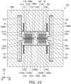
- FIG. 10 is a schematic plan view illustrating a sensor according to the first embodiment.
- a first counter beam 31A and a second counter beam 32A are provided in addition to the first beam 31 and the second beam 32.
- the configuration of the sensor 120 excluding this may be the same as the configuration of the sensor 110 .
- the first member 10M includes the first counter beam 31A, the second counter beam 32A, the first counter beam electrode 31AE and a second counter beam electrode 32AE.
- the first counter beam 31A and the second counter beam 32A extend along the second direction D2.
- the first counter beam 31A includes a first counter end 31Ae and a first counter other end 31Af.
- the first counter end 31Ae is connected to the first connection structure 21c.
- the first counter other end 31Af is connected to the first support region 10Ms.
- the second counter beam 32A includes a second counter end 32Ae and a second counter other end 32Af.
- the second counter end 32Ae is connected to the second connection structure 22c.
- the second counter other end 32Af is connected to the first support region 10Ms.
- the first counter beam electrode 31AE is connected to the first counter beam 31A.
- the first counter beam 31A is provided between the first counter beam electrode 31AE and the first beam electrode 31E in the third direction D3.
- the first beam 31 is provided between the first counter beam 31A and the first beam electrode 31E in the third direction D3.
- the second counter beam electrode 32AE is connected to the second counter beam 32A.
- the second counter beam 32A is provided between the second counter beam electrode 32AE and the second beam electrode 32E.
- the second beam 32 is provided between the second counter beam 32A and the second beam electrode 32E in the third direction D3.
- the first counter beam electrode 31AE and the second counter beam electrode 32AE satisfy at least one of the ninth condition, the tenth condition, the eleventh condition, the twelfth condition, the thirteenth condition, the fourteenth condition, the fifteenth condition, and the sixteenth condition.
- a wide dynamic range is also obtained in the sensor 120.
- a sensor capable of improving characteristics can be provided.
- the first electrode 51 and the first counter electrode 51A may be provided (see FIG. 3 ).
- the first electrode 51 faces the first beam electrode 31E.
- the first counter electrode 51A faces the first counter beam electrode 31AE.
- the second electrode 52 and the second counter electrode 52A may be provided (see FIG. 3 ).
- the second electrode 52 faces the second beam electrode 32E.
- the second counter electrode 52A faces the second counter beam electrode 32AE.
- the controller 70 (see FIG. 3 ) is configured to apply the drive signal including the AC component between the first electrode 51 and the first beam electrode 31E.
- the controller 70 is configured to detect the electrical signal generated between the first counter electrode 51A and the first counter beam electrode 31AE.
- the controller 70 (see FIG. 3 ) is configured to apply the drive signal including the AC component between the second electrode 52 and the second beam electrode 32E.
- the controller 70 is configured to detect the electrical signal generated between the second counter electrode 52A and the second counter beam electrode 32AE.
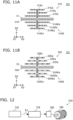
- FIG. 11A and FIG. 11B are schematic plan views illustrating a sensor according to the first embodiment.
- a plurality of first extending portions 31Ea are provided.
- One of the plurality of first extending portions 31Ea is provided between the first beam 31 and another one of the plurality of first extending portions 31Ea.
- the length of the one of the plurality of first extending portions 31Ea along the second direction D2 is longer than the length of the other one of the plurality of first extending portions 31Ea along the second direction D2.
- a plurality of first counter extending portions 31AEa may be provided.
- One of the plurality of first counter extending portions 31AEa is provided between the first beam 31 and another one of the plurality of first counter extending portions 31AEa.
- the length of the one of the plurality of first counter extending portions 31AEa along the second direction D2 is longer than the length of the other one of the plurality of first counter extending portions 31AEa along the second direction D2.
- a plurality of second extending portions 32Ea may be provided.
- One of the plurality of second extending portions 32Ea is provided between the second beam 32 and another one of the plurality of second extending portions 32Ea.
- the length of the one of the plurality of second extending portions 32Ea along the second direction D2 is longer than the length of the other one of the plurality of second extending portions 32Ea along the second direction D2.
- the first member 10M may be conductive.
- the first member 10M may include, for example, conductive silicon.
- the first member 10M may include, for example, a metal layer. For example, high heat dissipation can be obtained.
- the second embodiment relates to an electronic device.
- FIG. 12 is a schematic diagram illustrating an electronic device according to the second embodiment.
- an electronic device 310 includes the sensor according to the first embodiment and a circuit controller 170.
- the sensor 110 is drawn as the sensor.
- the circuit controller 170 is configured to control a circuit 180 based on a signal S1 obtained from the sensor.
- the circuit 180 is, for example, a control circuit of a driving device 185 or the like. According to the embodiment, for example, the circuit 180 for controlling the driving device 185 can be controlled with high precision.
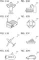
- FIGS. 13A to 13H are schematic diagrams illustrating applications of the electronic device according to the embodiment.
- the electronic device 310 may be at least a part of a robot. As shown in FIG. 13B , the electronic device 310 may be at least a part of a work robot provided in a manufacturing factory or the like. As shown in FIG. 13C , the electronic device 310 may be at least a part of an automated guided vehicle such as in a factory. As shown in FIG. 13D , the electronic device 310 may be at least a part of a drone (unmanned aerial vehicle). As shown in FIG. 13E , the electronic device 310 may be at least a part of an airplane. As shown in FIG. 13F , the electronic device 310 may be at least a part of a vessel. As shown in FIG. 13A , the electronic device 310 may be at least a part of a robot. As shown in FIG. 13B , the electronic device 310 may be at least a part of a work robot provided in a manufacturing factory or the like. As shown in FIG. 13C , the electronic device 310 may be at least a part of an automated
- the electronic device 310 may be at least a part of a submarine. As shown in FIG. 13H , the electronic device 310 may be at least a part of an automobile.
- the electronic device 310 may include, for example, at least one of a robot or a mobile object.
- FIGS. 14A and 14B are schematic diagrams illustrating applications of the sensor according to the embodiment.
- a sensor 430 includes the sensor according to the first embodiment and a transmitter/receiver 420.
- the sensor 110 is drawn as the sensor.
- the transmitter/receiver 420 is configured to transmit the signal obtained from the sensor 110 by at least one of wireless or wired methods, for example.
- the sensor 430 is provided, for example, on a slope surface 410 such as a road 400.
- the sensor 430 may, for example, monitor conditions such as facilities (e.g., infrastructure).
- the sensor 430 may be, for example, a condition monitoring device.
- the sensor 430 detects changes in the state of the slope surface 410 of the road 400 with high accuracy.
- a change in the state of the slope surface 410 includes, for example, at least one of a change in tilt angle or a change in vibration state.
- the signal (test result) obtained from the sensor 110 is transmitted by the transmitter/receiver 420.
- the condition of facilities e.g., infrastructure
- the sensor 430 is provided on a part of a bridge 460, for example.
- the bridge 460 is provided over a river 470.
- the bridge 460 includes at least one of main girder 450 and a bridge pier 440.
- the sensor 430 is provided on at least one of the main girder 450 and the bridge pier 440.
- the angle of at least one of the main girder 450 and the bridge pier 440 may change due to deterioration or the like.
- the vibration state may change.
- the sensor 430 detects these changes with high accuracy. A detection result can be transmitted to an arbitrary place by the transmitter/receiver 420. Anomalies can be effectively detected.
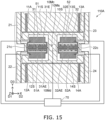
- FIG. 15 is a schematic plan view illustrating the sensor according to the first embodiment.
- At least a part of the first electrode 51 may be provided between the first beam 31 and the first beam electrode 31E in the third direction D3.
- At least a part of the second electrode 52 may be provided between the second beam 32 and the second beam electrode 32E in the third direction D3.
- At least a part of the first counter electrode 51A may be provided between the first beam 31 and the first counter beam electrode 31AE in the third direction D3.
- At least a part of the second counter electrode 52A may be provided between the second beam 32 and the second counter beam electrode 32AE in the third direction D3.
- FIG. 16 is a schematic plan view illustrating the sensor according to the first embodiment.
- a first extending electrode 51P, a second extending electrode 52P, a first counter extending electrode 51AP, and a second counter extending electrode 52AP is provided. Except for this, the configuration of the sensor 114A may be the same as the configuration of the sensor 114.
- At least a part of the first extending electrode 51P is provided between the plurality of portions (the plurality of first extending portions 31Ea) included in the first beam electrode 31E in the third direction D3.
- At least a part of the second extending electrode 52P is provided between the plurality of portions included in the second beam electrode 32E in the third direction D3.
- At least a part of the first counter extending electrode 51AP is provided between the plurality of portions included in the first counter beam electrode 31AE in the third direction D3.
- At least a part of the second counter extending electrode 52AP is provided between the plurality of portions included in the second counter beam electrode 32AE in the third direction D3.
- Each of the first extending electrode 51P, the second extending electrode 52P, the first counter extending electrode 51AP, and the second counter extending electrode 52AP may be electrically connected to the controller 70.
- FIG. 17 is a schematic plan view illustrating a sensor according to a third embodiment.
- FIG. 18 is a schematic cross-sectional view illustrating the sensor according to the third embodiment.
- FIG. 18 is a cross-sectional view taken along the line A1-A2 of FIG. 17 .
- a sensor 130 includes a base 50S, a first support portion 10S, a second support portion 20S, a third support portion 30S, and a first member 10M.
- the first support portion 10S, the second support portion 20S and the third support portion 30S are fixed to the base 50S.
- the first member 10M is supported by the first support portion 10S, the second support portion 20S and the third support portion 30S.
- a gap g1 is provided between the base 50S and the first member 10M.
- the first member 10M includes a first beam 31, a second beam 32, a first beam electrode 31E and a second beam electrode 32E.
- the first beam 31 and the second beam 32 extend along the second direction D2.
- the second direction D2 crosses the first direction D1 from the base 50S to the first support portion 10S.
- the first support portion 10S is provided between the second support portion 20S and the third support portion 30S in the second direction D2.
- the first beam 31 is supported by the second support portion 20S and the first support portion 10S.
- the second beam 32 is supported by the first support portion 10S and the third support portion 30S.
- the first beam electrode 31E is connected to the first beam 31.
- a third direction D3 from the first beam 31 to the first beam electrode 31E crosses a plane including the first direction D1 and the second direction D2.
- the second beam electrode 32E is connected to the second beam 32.
- the direction from the second beam 32 to the second beam electrode 32E is along the third direction D3.
- the first beam electrode 31E and the second beam electrode 32E satisfy at least one of the above mentioned, the first condition, the second condition, the third condition, the fourth condition, the fifth condition, the sixth condition, the seventh condition, or the eighth condition.
- this causes a difference in resonance frequency between the first beam 31 and the second beam 32, for example. This increases the dynamic range of detection.
- a sensor capable of improving characteristics can be provided.
- the first member 10M may further includes the first support region 10Ms, the second support region 20Ms, the third support region 30Ms, the first movable region 10Ma, the second movable region 10Mb, the first connection structure 21c and the second connection structure 22c.
- the first support portion 10S is provided between the base 50S and the first support region 10Ms in the first direction D1.
- the second support portion 20S is provided between base 50S and the second support region 20Ms in the first direction D1.
- the third support portion 30S is provided between the base 50S and the third support region 30Ms in the first direction D1.
- the first support region 10Ms is supported by the first support portion 10S.
- the second support region 20Ms is supported by the second support portion 20S.
- the third support region 30Ms is supported by the third support portion 30S.
- the first connection structure 21c is supported by the second support region 20Ms.
- the first beam 31 is supported by the first connection structure 21c and the first support region 10Ms.
- the second connection structure 22c is supported by the third support region 30Ms.
- the second beam 32 is supported by the first support region 10Ms and the second connection structure 22c.
- the sensor 130 may include the first electrode 51 and the first counter electrode 51A.
- the first electrode 51 and the first counter electrode 51A are fixed to the base 50S.
- the first member 10M includes the first counter beam electrode 31AE.
- the first counter beam electrode 31AE is connected to the first beam 31.
- the first beam 31 is provided between the first counter beam electrode 31AE and the first beam electrode 31E.
- the first electrode 51 faces the first beam electrode 31E.
- the first counter electrode 51A faces the first counter beam electrode 31AE.
- the sensor 130 may include the controller 70 (see FIG. 3 ).
- the controller 70 is configured to a drive signal including the AC component between the first electrode 51 and the first beam electrode 31E.
- the controller 70 is configured to detect the electrical signal generated between the first counter electrode 51A and the first counter beam electrode 31AE.
- the first member 10M may include the first counter beam electrode 31AE and the second counter beam electrode 32AE.
- the first counter beam electrode 31AE is connected to the first beam 31.
- the first beam 31 is provided between the first counter beam electrode 31AE and the first beam electrode 31E.
- the second counter beam electrode 32AE is connected to the second beam 32.
- the second beam 32 is provided between the second counter beam electrode 32AE and the second beam electrode 32E.
- the first counter beam electrode 31AE and the second counter beam electrode 32AE satisfy at least one of the ninth condition, the tenth condition, the eleventh condition, the twelfth condition, the thirteenth condition, the fourteenth condition, the fifteenth condition or the sixteenth condition.
- the first member 10M further includes the third movable region 10Mc and the first structure 21.
- the first beam electrode 31E is provided between the first beam 31 and the third movable region 10Mc in the third direction D3.
- the first member 10M may further include the third structure 23.
- the third structure 23 includes the third portion 23e, the third other portion 23f and the third intermediate portion 23m.
- the direction from the third portion 23e to the third other portion 23f is along the third direction D3.
- the third intermediate portion 23m is provided between the third portion 23e and the third other portion 23f.
- the third portion 23e is connected to the second connection structure 22c.
- the third other portion 23f is connected to the third movable region 10Mc.
- the third intermediate portion 23m is connected to the third support region 30Ms.
- the first member 10M may further include the fourth movable region 10Md and the second structure 22.
- the first counter beam electrode 31AE is provided between the fourth movable region 10Md and the first beam 31 in the third direction D3.
- the second structure 22 includes the second portion 22e, the second other portion 22f and the second intermediate portion 22m.
- the direction from the second other portion 22f to the second portion 22e is along the third direction D3.
- the second intermediate portion 22m is provided between the second other portion 22f and the second portion 22e.
- the second portion 22e is connected to the first connection structure 21c.
- the second other portion 22f is connected to the fourth movable region 10Md.
- the second intermediate portion 22m is connected to the second support region 20Ms.
- the first member 10M may further include the fourth structure 24.
- the fourth structure 24 includes the fourth portion 24e, the fourth other portion 24f and the fourth intermediate portion 24m.
- the direction from the fourth other portion 24f to the fourth portion 24e is along the third direction D3.
- the fourth intermediate portion 24m is provided between the fourth other portion 24f and the fourth portion 24e.
- the fourth portion 24e is connected to the second connection structure 22c.
- the fourth other portion 24f is connected to the fourth movable region 10Md.
- the fourth intermediate portion 24m is connected to the third support region 30Ms.
- the first member 10M may further include a first support structure 11S, a second support structure 12S, a third support structure 13S and a fourth support structure 14S.
- the first support structure 11S and the second support structure 12S are connected to the second support region 20Ms.
- the second support region 20Ms is provided between the first support structure 11S and the second support structure 12S in the third direction D3.
- the first movable region 10Ma is supported by the first support structure 11S and the second support structure 12S.
- the third support structure 13S and the fourth support structure 14S are connected to the third support region 30Ms.
- the third support region 30Ms is provided between the third support structure 13S and the fourth support structure 14S in the third direction D3.
- the second movable region 10Mb is supported by the third support structure 13S and the fourth support structure 14S.
- the first beam electrode 31E includes the first extending portion 31Ea and the first connecting portion 31Ex.
- the first extending portion 31Ea extends along the second direction D2.
- the first connecting portion 31Ex connects the first extending portion 31Ea to the first beam 31.
- the configuration of the first beam electrode 31E may be applied to the first counter beam electrode 31AE, the second beam electrode 32E, and the second counter beam electrode 32AE.
- a plurality of first extending portions 31Ea are provided in a sensor 131 according to the embodiment. Except for this, the configuration of the sensor 131 may be the same as the configuration of the sensor 130.
- the first connecting portion 31Ex connects the plurality of first extending portions 31Ea to each other.
- One of the plurality of first extending portions 31Ea is provided between the first beam 31 and another one of the plurality of first extending portions 31Ea.
- the length of the one of the first extending portions 31Ea along the second direction D2 is longer than the length of the other one of the first extending portions 31Ea along the second direction D2.
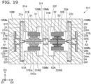
- FIG. 20 is a schematic plan view illustrating the sensor according to the third embodiment.
- the first member 10M further includes the first counter beam 31A, the second counter beam 32A, the first counter beam electrode 31AE and a second counter beam electrode 32AE. Except for this, the configuration of the sensor 132 may be the same as the configuration of the sensor 130.
- the first counter beam 31A and the second counter beam 32A extend along the second direction D2.
- the first counter beam 31A is supported by the second support portion 20S (second support region 20Ms) and the first support portion 10S (first support region 10Ms).
- the second counter beam 32A is supported by the first support portion 10S (first support region 10Ms) and the third support portion 30S (third support region 30Ms).
- the first counter beam electrode 31AE is connected to the first counter beam 31A.
- the direction from the first counter beam electrode 31AE to the first counter beam 31A is along the third direction D3.
- the second counter beam electrode 32AE is connected to the second counter beam 32A.
- the direction from the second counter beam electrode 32AE to the second counter beam 32A is along the third direction D3.
- FIG. 21 is a schematic plan view illustrating the sensor according to the third embodiment.
- the plurality of first extending portions 31Ea are provided in a sensor 133 according to the embodiment. Except for this, the configuration of the sensor 133 may be the same as the configuration of the sensor 132.
- the sensors 131 to 133 can also provide sensors whose characteristics can be improved.
- the sensors 130-133 may be applied to electronic device 310 ( FIG. 12 ).
- the first layer configuration may be the layer configuration of the first hole 31h.
- the second layer configuration may be the layer configuration of the second hole 32h.
- the first counter layer configuration may be the layer configuration of the first counter hole 31Ah.
- the second counter layer configuration may be the layer configuration of the second counter hole 32Ah.
- a sensor and an electronic devices capable of improving characteristics are provided.
Landscapes
- Physics & Mathematics (AREA)
- General Physics & Mathematics (AREA)
- Engineering & Computer Science (AREA)
- Radar, Positioning & Navigation (AREA)
- Remote Sensing (AREA)
- Manufacturing & Machinery (AREA)
- Pressure Sensors (AREA)
Claims (12)
- Capteur (110), comprenant un substratune base (50S) ;une première partie de support (10S) fixée au substrat ; etun premier élément (10M) supporté par la première partie de support,un interstice (g1) étant prévu entre la base et le premier élément,le premier élément incluant une première région de support (10Ms), une première structure de raccordement (21c), une seconde structure de raccordement (22c), une première poutre (31), une seconde poutre (32), une électrode de première poutre (31E), et une électrode de seconde poutre (32E),la première partie de support étant prévue entre la base et la première région de support dans une première direction (D1) depuis la base vers la première partie de support,la première région de support étant supportée par la première partie de support,la première poutre et la seconde poutre s'étendant le long d'une deuxième direction (D2) croisant la première direction,une direction depuis la première structure de raccordement vers la seconde structure de raccordement s'étendant le long de la deuxième direction,la première région de support étant prévue entre la première structure de raccordement et la seconde structure de raccordement dans la deuxième direction,la première poutre incluant une première extrémité (31e) et une première autre extrémité (31f),
la première extrémité étant raccordée à la première structure de raccordement, la première autre extrémité étant raccordée à la première région de support,la seconde poutre incluant une seconde extrémité (32e) et une seconde autre extrémité (32f),
la seconde extrémité étant raccordée à la seconde structure de raccordement, la seconde autre extrémité étant raccordée à la première région de support,l'électrode de première poutre étant raccordée à la première poutre,une troisième direction (D3) depuis la première poutre vers l'électrode de première poutre croisant un plan incluant la première direction et la deuxième direction,l'électrode de seconde poutre étant raccordée à la seconde poutre,une direction depuis la seconde poutre vers l'électrode de seconde poutre s'étendant le long de la troisième direction ;l'électrode de première poutre et l'électrode de seconde poutre satisfaisant au moins à une parmi une première condition, une deuxième condition, une troisième condition, une quatrième condition, une cinquième condition, une sixième condition, une septième condition, ou une huitième condition,dans la première condition, une seconde masse de l'électrode de seconde poutre étant différente d'une première masse de l'électrode de première poutre,dans la deuxième condition, une seconde épaisseur le long de la première direction de l'électrode de seconde poutre étant différente d'une première épaisseur le long de la première direction de l'électrode de première poutre,dans la troisième condition, au moins une partie du second matériau inclus dans l'électrode de seconde poutre étant différente d'au moins une partie du premier matériau inclus dans l'électrode de première poutre,dans la quatrième condition, une seconde taille d'un second trou (32h) inclus dans l'électrode de seconde poutre étant différente d'une première taille d'un premier trou (31h) inclus dans l'électrode de première poutre,dans la cinquième condition, une seconde densité du second trou étant différente d'une première densité du premier trou,dans la sixième condition, un second nombre des seconds trous étant différent d'un premier nombre des premiers trous,dans la septième condition, une seconde forme du second trou étant différente d'une première forme du premier trou, etdans la huitième condition, une seconde configuration de couche de l'électrode de seconde poutre étant différente d'une première configuration de couche de l'électrode de première poutre. - Capteur selon la revendication 1, dans lequelle premier élément inclut en outre une première région mobile (10Ma) et une seconde région mobile (10Mb),dans la deuxième direction, la première région de support est prévue entre la première région mobile et la seconde région mobile,la première structure de raccordement est supportée par la première région mobile, la première structure de raccordement est prévue entre la première région mobile et la première région de support dans la deuxième direction,la seconde structure de raccordement est supportée par la seconde région mobile, etla seconde structure de raccordement est prévue entre la première région de support et la seconde région mobile dans la deuxième direction.
- Capteur selon la revendication 2, comprenant en outre :une première électrode (51) fixée à la base ; etune première contre-électrode (51A) fixée à la base,le premier élément incluant en outre une électrode de première contre-poutre (31AE) raccordée à la première poutre,dans la troisième direction, la première poutre étant prévue entre l'électrode de première contre-poutre et l'électrode de première poutre,la première électrode faisant face à l'électrode de première poutre, etla première contre-électrode faisant face à l'électrode de première contre-poutre.
- Capteur selon la revendication 3, comprenant en outre :un contrôleur (70)le contrôleur étant configuré pour appliquer un signal d'entraînement incluant une composante AC entre la première électrode et l'électrode de première poutre, etle contrôleur étant configuré pour détecter un signal électrique généré entre la première contre-électrode et l'électrode de première contre-poutre.
- Capteur selon la revendication 2, dans lequelle premier élément inclut une électrode de première contre-poutre (31AE) et une électrode de seconde contre-poutre (32AE),l'électrode de première contre-poutre est raccordée à la première poutre,dans la troisième direction, la première poutre est prévue entre l'électrode de première contre-poutre et l'électrode de première poutre,l'électrode de seconde contre-poutre est raccordée à la seconde poutre,dans la troisième direction, la seconde poutre est prévue entre l'électrode de seconde contre-poutre et l'électrode de seconde poutre,l'électrode de première contre-poutre et l'électrode de seconde contre-poutre satisfont à au moins une parmi une neuvième condition, une dixième condition, une onzième condition, une douzième condition, une treizième condition, une quatorzième condition, une quinzième condition, ou une seizième condition,dans la neuvième condition, une seconde contre-masse de l'électrode de seconde contre-poutre est différente d'une première contre-masse de l'électrode de première contre-poutre,dans la dixième condition, une seconde contre-épaisseur le long de la première direction de l'électrode de seconde contre-poutre est différente d'une première contre-épaisseur le long de la première direction de l'électrode de première contre-poutre,dans la onzième condition, au moins une partie d'un second contre-matériau inclus dans l'électrode de seconde contre-poutre est différente d'au moins une partie d'un premier contre-matériau inclus dans l'électrode de première contre-poutre,dans la douzième condition, une seconde contre-taille du second contre-trou inclus dans l'électrode de seconde contre-poutre est différente d'une première contre-taille du premier contre-trou inclus dans l'électrode de première contre-poutre,dans la treizième condition, une seconde contre-densité du second contre-trou est différente d'une première contre-densité du premier contre-trou,dans la quatorzième condition, un nombre des seconds contre-trous est différent d'un nombre des premiers contre-trous,dans la quinzième condition, une seconde contre-forme du second contre-trou est différente d'une première contre-forme du premier contre-trou, etdans la seizième condition, une seconde contre-configuration de couche de l'électrode de seconde contre-poutre est différente d'une première contre-configuration de couche de l'électrode de première contre-poutre.
- Capteur selon la revendication 5, dans lequelle premier élément inclut en outre une première structure (21) et une première structure de support (11S),une position de première structure de la première structure dans la deuxième direction est située entre une position de première région mobile de la première région mobile dans la deuxième direction et une position de première poutre de la première poutre dans la deuxième direction,une position de première structure de raccordement de la première structure de raccordement dans la deuxième direction est située entre la position de première structure et la position de première poutre,une position de première structure de support dans la deuxième direction de la première structure de support est située entre la position de première structure et une position de première région de support dans la deuxième direction de la première région de support,la première structure inclut une première partie (21e), une première autre partie (21f), et une première partie intermédiaire (21m),une direction depuis la première partie vers la première autre partie s'étend le long de la troisième direction,la première partie intermédiaire est prévue entre la première partie et la première autre partie,la première partie est raccordée à la première structure de raccordement,la première autre partie est raccordée à la première région mobile, etla première partie intermédiaire est raccordée à la première structure de support.
- Capteur selon la revendication 6, dans lequelle premier élément inclut en outre une troisième structure (23) et une troisième structure de support (13S),une position de troisième structure de la troisième structure dans la deuxième direction est située entre une position de seconde poutre de la seconde poutre dans la deuxième direction et une position de seconde région mobile de la seconde région mobile dans la deuxième direction,une position de seconde structure de raccordement de la seconde structure de raccordement dans la deuxième direction est située entre la position de seconde poutre et la position de troisième structure, etune position de troisième structure de support dans la deuxième direction de la troisième structure de support est située entre la position de première région de support et la position de troisième structure,la troisième structure inclut une troisième partie (23e), une troisième autre partie (23f), et une troisième partie intermédiaire (23m),une direction depuis la troisième partie vers la troisième autre partie s'étend le long de la troisième direction,la troisième partie intermédiaire est prévue entre la troisième partie et la troisième autre partie ;la troisième partie est raccordée à la seconde structure de raccordement,la troisième autre partie est raccordée à la seconde région mobile, etla troisième partie intermédiaire est raccordée à la troisième structure de support.
- Capteur selon la revendication 7, dans lequelle premier élément inclut en outre une deuxième structure (22) et une deuxième structure de support (12S),une position de deuxième structure de la deuxième structure dans la deuxième direction est située entre la position de première région mobile et la position de première poutre,une position de deuxième structure de support de la deuxième structure de support dans la deuxième direction est située entre la position de deuxième structure et la position de première région de support,la deuxième structure inclut une deuxième partie (22e), une deuxième autre partie (22f), et une deuxième partie intermédiaire (22m),une direction depuis la deuxième autre partie vers la deuxième partie s'étend le long de la troisième direction,la deuxième partie intermédiaire est prévue entre la deuxième autre partie et la deuxième partie,la deuxième partie est raccordée à la première structure de raccordement,la deuxième autre partie est raccordée à la première région mobile,la deuxième partie intermédiaire est raccordée à la deuxième structure de support, etdans la troisième direction, la première structure de raccordement est prévue entre au moins une partie de la deuxième structure de support et au moins une partie de la première structure de support.
- Capteur selon la revendication 8, dans lequelle premier élément inclut une quatrième structure (24) et une quatrième structure de support (14S),une position de quatrième structure dans la deuxième direction de la quatrième structure est située entre la position de seconde poutre et la position de seconde région mobile,une position de quatrième structure de support dans la deuxième direction de la quatrième structure de support est située entre la position de première région de support et la position de quatrième structure,la quatrième structure inclut une quatrième partie (24e), une quatrième autre partie (24f), et une quatrième partie intermédiaire (24m),une direction depuis la quatrième autre partie vers la quatrième partie s'étend le long de la troisième direction, la quatrième partie intermédiaire est prévue entre la quatrième autre partie et la quatrième partie,la quatrième partie est raccordée à la seconde structure de raccordement,la quatrième autre partie est raccordée à la seconde région mobile,la quatrième partie intermédiaire est raccordée à la quatrième structure de support, etdans la troisième direction, la seconde structure de raccordement est prévue entre au moins une partie de la quatrième structure de support et au moins une partie de la troisième structure de support.
- Capteur selon l'une quelconque des revendications 1 à 9, dans lequel
l'électrode de première poutre inclut :une première partie d'extension (31Ea) s'étendant dans la deuxième direction, etune première partie de raccordement (31Ex) raccordant la première partie d'extension à la première poutre. - Capteur selon la revendication 2, dans lequelle premier élément inclut en outre une première structure (21) et une première structure de support (11S),une position de première structure de la première structure dans la deuxième direction est située entre une position de première région mobile de la première région mobile dans la deuxième direction et une position de première poutre de la première poutre dans la deuxième direction,une position de première structure de raccordement de la première structure de raccordement dans la deuxième direction est située entre la position de première structure et la position de première poutre,une position de première structure de support dans la deuxième direction de la première structure de support est située entre la position de première structure et une position de première région de support dans la deuxième direction de la première région de support,la première structure inclut une première partie (21e), une première autre partie (21f), et une première partie intermédiaire (21m),une direction depuis la première partie vers la première autre partie s'étend le long de la troisième direction,la première partie intermédiaire est prévue entre la première partie et la première autre partie,la première partie est raccordée à la première structure de raccordement,la première autre partie est raccordée à la première région mobile,la première partie intermédiaire est raccordée à la première structure de support,le premier élément inclut une première contre-poutre (31a), une seconde contre-poutre (32A), une électrode de première contre-poutre (31AE), et une électrode de seconde contre-poutre (32AE),la première contre-poutre et la seconde contre-poutre s'étendent dans la deuxième direction,la première contre-poutre inclut une première contre-extrémité (31Ae) et une première contre-autre extrémité (31Af),la première contre-extrémité est raccordée à la première structure de raccordement, et la première contre-autre extrémité est raccordée à la première région de support,la seconde contre-poutre inclut une seconde contre-extrémité (32Ae) et une seconde contre-autre extrémité (32Af),
la seconde contre-extrémité est raccordée à la seconde structure de raccordement, et la seconde contre-extrémité est raccordée à la première région de support,l'électrode de première contre-poutre est raccordée à la première contre-poutre,dans la troisième direction, la première contre-poutre est prévue entre l'électrode de première contre-poutre et l'électrode de première poutre,dans la troisième direction, la première poutre est prévue entre la première contre-poutre et l'électrode de première poutre,l'électrode de seconde contre-poutre est raccordée à la seconde contre-poutre,dans la troisième direction, la seconde contre-poutre est prévue entre l'électrode de seconde contre-poutre et l'électrode de seconde poutre,dans la troisième direction, la seconde poutre est prévue entre la seconde contre-poutre et l'électrode de seconde poutre,l'électrode de première contre-poutre et l'électrode de seconde contre-poutre satisfont à au moins une parmi une neuvième condition, une dixième condition, une onzième condition, une douzième condition, une treizième condition, une quatorzième condition, une quinzième condition ou une seizième condition,dans la neuvième condition, une seconde contre-masse de l'électrode de seconde contre-poutre est différente d'une première contre-masse de l'électrode de première contre-poutre,dans la dixième condition, une seconde contre-épaisseur le long de la première direction de l'électrode de seconde contre-poutre est différente d'une première contre-épaisseur le long de la première direction de l'électrode de première contre-poutre,dans la onzième condition, au moins une partie d'un second contre-matériau inclus dans l'électrode de seconde contre-poutre est différente d'au moins une partie d'un premier contre-matériau inclus dans l'électrode de première contre-poutre,dans la douzième condition, une seconde contre-taille d'un second contre-trou (32Ah) inclus dans l'électrode de seconde contre-poutre est différente d'une première contre-taille d'un premier contre-trou (31Ah) inclus dans l'électrode de première contre-poutre,dans la treizième condition, une seconde contre-densité du second contre-trou est différente d'une première contre-densité du premier contre-trou,dans la quatorzième condition, un nombre des seconds contre-trous est différent d'un nombre des premiers contre-trous, dans la quinzième condition, la seconde contre-forme du second contre-trou est différente de la première contre-forme du premier contre-trou, etdans la seizième condition, une seconde contre-configuration de couche de l'électrode de seconde contre-poutre est différente d'une première contre-configuration de couche de l'électrode de première contre-poutre. - Dispositif électronique, comprenant :le capteur selon l'une quelconque des revendications 1 à 11 ; etun contrôleur de circuit (170) configuré pour contrôler un circuit (180) sur la base d'un signal obtenu en provenance du capteur.
Applications Claiming Priority (2)
| Application Number | Priority Date | Filing Date | Title |
|---|---|---|---|
| JP2022146097 | 2022-09-14 | ||
| JP2023004635A JP7832136B2 (ja) | 2022-09-14 | 2023-01-16 | センサ及び電子装置 |
Publications (2)
| Publication Number | Publication Date |
|---|---|
| EP4339622A1 EP4339622A1 (fr) | 2024-03-20 |
| EP4339622B1 true EP4339622B1 (fr) | 2024-11-20 |
Family
ID=85238929
Family Applications (1)
| Application Number | Title | Priority Date | Filing Date |
|---|---|---|---|
| EP23156529.2A Active EP4339622B1 (fr) | 2022-09-14 | 2023-02-14 | Capteur et dispositif électronique |
Country Status (2)
| Country | Link |
|---|---|
| US (1) | US12529561B2 (fr) |
| EP (1) | EP4339622B1 (fr) |
Family Cites Families (12)
| Publication number | Priority date | Publication date | Assignee | Title |
|---|---|---|---|---|
| DE102009026462B4 (de) * | 2009-05-26 | 2023-03-30 | Robert Bosch Gmbh | Beschleunigungssensor |
| US8471643B2 (en) * | 2011-05-13 | 2013-06-25 | Qualcomm Mems Technologies, Inc. | Electromechanical systems oscillator with piezoelectric contour mode resonator for multiple frequency generation |
| GB2505875A (en) * | 2012-09-04 | 2014-03-19 | Cambridge Entpr Ltd | Dual and triple axis inertial sensors and methods of inertial sensing |
| JP5978140B2 (ja) * | 2013-01-24 | 2016-08-24 | 日立オートモティブシステムズ株式会社 | 慣性センサ |
| KR101454123B1 (ko) * | 2013-08-29 | 2014-10-22 | 삼성전기주식회사 | 가속도 센서 |
| EP3546954B1 (fr) * | 2016-01-07 | 2022-12-14 | Analog Devices, Inc. | Accéléromètre angulaire triaxial |
| JP6812830B2 (ja) * | 2017-02-20 | 2021-01-13 | セイコーエプソン株式会社 | ジャイロセンサー、電子機器、および移動体 |
| JP2019012767A (ja) | 2017-06-30 | 2019-01-24 | ルネサスエレクトロニクス株式会社 | 半導体モジュールの製造方法および半導体モジュール |
| US10866258B2 (en) * | 2018-07-20 | 2020-12-15 | Honeywell International Inc. | In-plane translational vibrating beam accelerometer with mechanical isolation and 4-fold symmetry |
| US11005446B2 (en) * | 2019-05-07 | 2021-05-11 | Fox Enterprises, Inc. | Resonators and devices with a pixel electrode operating across a gap |
| US11307217B1 (en) * | 2019-06-21 | 2022-04-19 | Facebook Technologies, Llc | Resonant accelerometer |
| IT202100023795A1 (it) * | 2021-09-15 | 2023-03-15 | St Microelectronics Srl | Accelerometro risonante ad asse z con struttura di rilevamento avente prestazioni migliorate |
-
2023
- 2023-02-14 EP EP23156529.2A patent/EP4339622B1/fr active Active
- 2023-02-24 US US18/174,551 patent/US12529561B2/en active Active
Also Published As
| Publication number | Publication date |
|---|---|
| US20240085181A1 (en) | 2024-03-14 |
| EP4339622A1 (fr) | 2024-03-20 |
| US12529561B2 (en) | 2026-01-20 |
Similar Documents
| Publication | Publication Date | Title |
|---|---|---|
| US12019092B2 (en) | Sensor and electronic device | |
| US11834326B2 (en) | Sensor and electronic device | |
| EP4339622B1 (fr) | Capteur et dispositif électronique | |
| EP4516724A1 (fr) | Capteur, système de capteur et dispositif électronique | |
| US20250076047A1 (en) | Sensor, sensor system, and electronic device | |
| US20250076046A1 (en) | Sensor, sensor system, and electronic device | |
| JP7832136B2 (ja) | センサ及び電子装置 | |
| US20250383366A1 (en) | Sensor and electronic device | |
| EP4339620B1 (fr) | Capteur et dispositif électronique | |
| US20250264496A1 (en) | Sensor and electronic device | |
| US20240310406A1 (en) | Sensor and electronic device | |
| EP4431448A1 (fr) | Capteur et dispositif électronique | |
| US20250076054A1 (en) | Sensor, sensor system, and electronic device | |
| US20260079173A1 (en) | Sensor and electronic device | |
| US20250076049A1 (en) | Sensor, sensor system, and electronic device | |
| US20230288202A1 (en) | Sensor and electronic device | |
| EP4235098B1 (fr) | Capteur | |
| US20240401949A1 (en) | Sensor and electronic device | |
| US20250076089A1 (en) | Sensor, sensor system, and electronic device |
Legal Events
| Date | Code | Title | Description |
|---|---|---|---|
| PUAI | Public reference made under article 153(3) epc to a published international application that has entered the european phase |
Free format text: ORIGINAL CODE: 0009012 |
|
| STAA | Information on the status of an ep patent application or granted ep patent |
Free format text: STATUS: REQUEST FOR EXAMINATION WAS MADE |
|
| 17P | Request for examination filed |
Effective date: 20230214 |
|
| AK | Designated contracting states |
Kind code of ref document: A1 Designated state(s): AL AT BE BG CH CY CZ DE DK EE ES FI FR GB GR HR HU IE IS IT LI LT LU LV MC ME MK MT NL NO PL PT RO RS SE SI SK SM TR |
|
| GRAP | Despatch of communication of intention to grant a patent |
Free format text: ORIGINAL CODE: EPIDOSNIGR1 |
|
| STAA | Information on the status of an ep patent application or granted ep patent |
Free format text: STATUS: GRANT OF PATENT IS INTENDED |
|
| RIC1 | Information provided on ipc code assigned before grant |
Ipc: B81B 5/00 20060101ALN20240603BHEP Ipc: G01P 15/08 20060101ALI20240603BHEP Ipc: G01P 15/097 20060101AFI20240603BHEP |
|
| INTG | Intention to grant announced |
Effective date: 20240618 |
|
| GRAS | Grant fee paid |
Free format text: ORIGINAL CODE: EPIDOSNIGR3 |
|
| GRAA | (expected) grant |
Free format text: ORIGINAL CODE: 0009210 |
|
| STAA | Information on the status of an ep patent application or granted ep patent |
Free format text: STATUS: THE PATENT HAS BEEN GRANTED |
|
| AK | Designated contracting states |
Kind code of ref document: B1 Designated state(s): AL AT BE BG CH CY CZ DE DK EE ES FI FR GB GR HR HU IE IS IT LI LT LU LV MC ME MK MT NL NO PL PT RO RS SE SI SK SM TR |
|
| REG | Reference to a national code |
Ref country code: GB Ref legal event code: FG4D |
|
| REG | Reference to a national code |
Ref country code: CH Ref legal event code: EP |
|
| REG | Reference to a national code |
Ref country code: DE Ref legal event code: R096 Ref document number: 602023001042 Country of ref document: DE |
|
| REG | Reference to a national code |
Ref country code: IE Ref legal event code: FG4D |
|
| REG | Reference to a national code |
Ref country code: LT Ref legal event code: MG9D |
|
| REG | Reference to a national code |
Ref country code: NL Ref legal event code: MP Effective date: 20241120 |
|
| PG25 | Lapsed in a contracting state [announced via postgrant information from national office to epo] |
Ref country code: HR Free format text: LAPSE BECAUSE OF FAILURE TO SUBMIT A TRANSLATION OF THE DESCRIPTION OR TO PAY THE FEE WITHIN THE PRESCRIBED TIME-LIMIT Effective date: 20241120 Ref country code: IS Free format text: LAPSE BECAUSE OF FAILURE TO SUBMIT A TRANSLATION OF THE DESCRIPTION OR TO PAY THE FEE WITHIN THE PRESCRIBED TIME-LIMIT Effective date: 20250320 Ref country code: PT Free format text: LAPSE BECAUSE OF FAILURE TO SUBMIT A TRANSLATION OF THE DESCRIPTION OR TO PAY THE FEE WITHIN THE PRESCRIBED TIME-LIMIT Effective date: 20250320 |
|
| PG25 | Lapsed in a contracting state [announced via postgrant information from national office to epo] |
Ref country code: FI Free format text: LAPSE BECAUSE OF FAILURE TO SUBMIT A TRANSLATION OF THE DESCRIPTION OR TO PAY THE FEE WITHIN THE PRESCRIBED TIME-LIMIT Effective date: 20241120 Ref country code: NL Free format text: LAPSE BECAUSE OF FAILURE TO SUBMIT A TRANSLATION OF THE DESCRIPTION OR TO PAY THE FEE WITHIN THE PRESCRIBED TIME-LIMIT Effective date: 20241120 |
|
| REG | Reference to a national code |
Ref country code: AT Ref legal event code: MK05 Ref document number: 1744028 Country of ref document: AT Kind code of ref document: T Effective date: 20241120 |
|
| PG25 | Lapsed in a contracting state [announced via postgrant information from national office to epo] |
Ref country code: BG Free format text: LAPSE BECAUSE OF FAILURE TO SUBMIT A TRANSLATION OF THE DESCRIPTION OR TO PAY THE FEE WITHIN THE PRESCRIBED TIME-LIMIT Effective date: 20241120 |
|
| PG25 | Lapsed in a contracting state [announced via postgrant information from national office to epo] |
Ref country code: ES Free format text: LAPSE BECAUSE OF FAILURE TO SUBMIT A TRANSLATION OF THE DESCRIPTION OR TO PAY THE FEE WITHIN THE PRESCRIBED TIME-LIMIT Effective date: 20241120 |
|
| PG25 | Lapsed in a contracting state [announced via postgrant information from national office to epo] |
Ref country code: NO Free format text: LAPSE BECAUSE OF FAILURE TO SUBMIT A TRANSLATION OF THE DESCRIPTION OR TO PAY THE FEE WITHIN THE PRESCRIBED TIME-LIMIT Effective date: 20250220 |
|
| PG25 | Lapsed in a contracting state [announced via postgrant information from national office to epo] |
Ref country code: GR Free format text: LAPSE BECAUSE OF FAILURE TO SUBMIT A TRANSLATION OF THE DESCRIPTION OR TO PAY THE FEE WITHIN THE PRESCRIBED TIME-LIMIT Effective date: 20250221 Ref country code: LV Free format text: LAPSE BECAUSE OF FAILURE TO SUBMIT A TRANSLATION OF THE DESCRIPTION OR TO PAY THE FEE WITHIN THE PRESCRIBED TIME-LIMIT Effective date: 20241120 Ref country code: AT Free format text: LAPSE BECAUSE OF FAILURE TO SUBMIT A TRANSLATION OF THE DESCRIPTION OR TO PAY THE FEE WITHIN THE PRESCRIBED TIME-LIMIT Effective date: 20241120 |
|
| PG25 | Lapsed in a contracting state [announced via postgrant information from national office to epo] |
Ref country code: PL Free format text: LAPSE BECAUSE OF FAILURE TO SUBMIT A TRANSLATION OF THE DESCRIPTION OR TO PAY THE FEE WITHIN THE PRESCRIBED TIME-LIMIT Effective date: 20241120 |
|
| PG25 | Lapsed in a contracting state [announced via postgrant information from national office to epo] |
Ref country code: RS Free format text: LAPSE BECAUSE OF FAILURE TO SUBMIT A TRANSLATION OF THE DESCRIPTION OR TO PAY THE FEE WITHIN THE PRESCRIBED TIME-LIMIT Effective date: 20250220 |
|
| PG25 | Lapsed in a contracting state [announced via postgrant information from national office to epo] |
Ref country code: SM Free format text: LAPSE BECAUSE OF FAILURE TO SUBMIT A TRANSLATION OF THE DESCRIPTION OR TO PAY THE FEE WITHIN THE PRESCRIBED TIME-LIMIT Effective date: 20241120 |
|
| PG25 | Lapsed in a contracting state [announced via postgrant information from national office to epo] |
Ref country code: DK Free format text: LAPSE BECAUSE OF FAILURE TO SUBMIT A TRANSLATION OF THE DESCRIPTION OR TO PAY THE FEE WITHIN THE PRESCRIBED TIME-LIMIT Effective date: 20241120 |
|
| PG25 | Lapsed in a contracting state [announced via postgrant information from national office to epo] |
Ref country code: EE Free format text: LAPSE BECAUSE OF FAILURE TO SUBMIT A TRANSLATION OF THE DESCRIPTION OR TO PAY THE FEE WITHIN THE PRESCRIBED TIME-LIMIT Effective date: 20241120 |
|
| PG25 | Lapsed in a contracting state [announced via postgrant information from national office to epo] |
Ref country code: RO Free format text: LAPSE BECAUSE OF FAILURE TO SUBMIT A TRANSLATION OF THE DESCRIPTION OR TO PAY THE FEE WITHIN THE PRESCRIBED TIME-LIMIT Effective date: 20241120 |
|
| PG25 | Lapsed in a contracting state [announced via postgrant information from national office to epo] |
Ref country code: SK Free format text: LAPSE BECAUSE OF FAILURE TO SUBMIT A TRANSLATION OF THE DESCRIPTION OR TO PAY THE FEE WITHIN THE PRESCRIBED TIME-LIMIT Effective date: 20241120 |
|
| PG25 | Lapsed in a contracting state [announced via postgrant information from national office to epo] |
Ref country code: CZ Free format text: LAPSE BECAUSE OF FAILURE TO SUBMIT A TRANSLATION OF THE DESCRIPTION OR TO PAY THE FEE WITHIN THE PRESCRIBED TIME-LIMIT Effective date: 20241120 |
|
| PG25 | Lapsed in a contracting state [announced via postgrant information from national office to epo] |
Ref country code: IT Free format text: LAPSE BECAUSE OF FAILURE TO SUBMIT A TRANSLATION OF THE DESCRIPTION OR TO PAY THE FEE WITHIN THE PRESCRIBED TIME-LIMIT Effective date: 20241120 |
|
| REG | Reference to a national code |
Ref country code: DE Ref legal event code: R097 Ref document number: 602023001042 Country of ref document: DE |
|
| PG25 | Lapsed in a contracting state [announced via postgrant information from national office to epo] |
Ref country code: SE Free format text: LAPSE BECAUSE OF FAILURE TO SUBMIT A TRANSLATION OF THE DESCRIPTION OR TO PAY THE FEE WITHIN THE PRESCRIBED TIME-LIMIT Effective date: 20241120 |
|
| PG25 | Lapsed in a contracting state [announced via postgrant information from national office to epo] |
Ref country code: MC Free format text: LAPSE BECAUSE OF FAILURE TO SUBMIT A TRANSLATION OF THE DESCRIPTION OR TO PAY THE FEE WITHIN THE PRESCRIBED TIME-LIMIT Effective date: 20241120 |
|
| PLBE | No opposition filed within time limit |
Free format text: ORIGINAL CODE: 0009261 |
|
| STAA | Information on the status of an ep patent application or granted ep patent |
Free format text: STATUS: NO OPPOSITION FILED WITHIN TIME LIMIT |
|
| PG25 | Lapsed in a contracting state [announced via postgrant information from national office to epo] |
Ref country code: LU Free format text: LAPSE BECAUSE OF NON-PAYMENT OF DUE FEES Effective date: 20250214 |
|
| 26N | No opposition filed |
Effective date: 20250821 |
|
| REG | Reference to a national code |
Ref country code: BE Ref legal event code: MM Effective date: 20250228 |
|
| PGFP | Annual fee paid to national office [announced via postgrant information from national office to epo] |
Ref country code: FR Payment date: 20251208 Year of fee payment: 4 |
|
| PG25 | Lapsed in a contracting state [announced via postgrant information from national office to epo] |
Ref country code: BE Free format text: LAPSE BECAUSE OF NON-PAYMENT OF DUE FEES Effective date: 20250228 |
|
| PG25 | Lapsed in a contracting state [announced via postgrant information from national office to epo] |
Ref country code: IE Free format text: LAPSE BECAUSE OF NON-PAYMENT OF DUE FEES Effective date: 20250214 |
|
| PGFP | Annual fee paid to national office [announced via postgrant information from national office to epo] |
Ref country code: DE Payment date: 20251224 Year of fee payment: 4 |