EP4339728A1 - Schubsteuerungsverfahren für einen wandkletterroboter - Google Patents
Schubsteuerungsverfahren für einen wandkletterroboter Download PDFInfo
- Publication number
- EP4339728A1 EP4339728A1 EP23197966.7A EP23197966A EP4339728A1 EP 4339728 A1 EP4339728 A1 EP 4339728A1 EP 23197966 A EP23197966 A EP 23197966A EP 4339728 A1 EP4339728 A1 EP 4339728A1
- Authority
- EP
- European Patent Office
- Prior art keywords
- rotating
- thrust
- ducts
- included angle
- robot
- Prior art date
- Legal status (The legal status is an assumption and is not a legal conclusion. Google has not performed a legal analysis and makes no representation as to the accuracy of the status listed.)
- Granted
Links
Images
Classifications
-
- G—PHYSICS
- G05—CONTROLLING; REGULATING
- G05D—SYSTEMS FOR CONTROLLING OR REGULATING NON-ELECTRIC VARIABLES
- G05D1/00—Control of position, course, altitude or attitude of land, water, air or space vehicles, e.g. using automatic pilots
- G05D1/08—Control of attitude, i.e. control of roll, pitch, or yaw
- G05D1/0891—Control of attitude, i.e. control of roll, pitch, or yaw specially adapted for land vehicles
-
- B—PERFORMING OPERATIONS; TRANSPORTING
- B62—LAND VEHICLES FOR TRAVELLING OTHERWISE THAN ON RAILS
- B62D—MOTOR VEHICLES; TRAILERS
- B62D57/00—Vehicles characterised by having other propulsion or other ground- engaging means than wheels or endless track, alone or in addition to wheels or endless track
- B62D57/02—Vehicles characterised by having other propulsion or other ground- engaging means than wheels or endless track, alone or in addition to wheels or endless track with ground-engaging propulsion means, e.g. walking members
- B62D57/024—Vehicles characterised by having other propulsion or other ground- engaging means than wheels or endless track, alone or in addition to wheels or endless track with ground-engaging propulsion means, e.g. walking members specially adapted for moving on inclined or vertical surfaces
-
- B—PERFORMING OPERATIONS; TRANSPORTING
- B62—LAND VEHICLES FOR TRAVELLING OTHERWISE THAN ON RAILS
- B62D—MOTOR VEHICLES; TRAILERS
- B62D57/00—Vehicles characterised by having other propulsion or other ground- engaging means than wheels or endless track, alone or in addition to wheels or endless track
- B62D57/04—Vehicles characterised by having other propulsion or other ground- engaging means than wheels or endless track, alone or in addition to wheels or endless track having other than ground-engaging propulsion means, e.g. having propellers
-
- B—PERFORMING OPERATIONS; TRANSPORTING
- B64—AIRCRAFT; AVIATION; COSMONAUTICS
- B64C—AEROPLANES; HELICOPTERS
- B64C27/00—Rotorcraft; Rotors peculiar thereto
- B64C27/04—Helicopters
- B64C27/08—Helicopters with two or more rotors
-
- B—PERFORMING OPERATIONS; TRANSPORTING
- B64—AIRCRAFT; AVIATION; COSMONAUTICS
- B64C—AEROPLANES; HELICOPTERS
- B64C27/00—Rotorcraft; Rotors peculiar thereto
- B64C27/20—Rotorcraft characterised by having shrouded rotors, e.g. flying platforms
-
- B—PERFORMING OPERATIONS; TRANSPORTING
- B64—AIRCRAFT; AVIATION; COSMONAUTICS
- B64C—AEROPLANES; HELICOPTERS
- B64C27/00—Rotorcraft; Rotors peculiar thereto
- B64C27/52—Tilting of rotor bodily relative to fuselage
-
- G—PHYSICS
- G05—CONTROLLING; REGULATING
- G05D—SYSTEMS FOR CONTROLLING OR REGULATING NON-ELECTRIC VARIABLES
- G05D1/00—Control of position, course, altitude or attitude of land, water, air or space vehicles, e.g. using automatic pilots
- G05D1/02—Control of position or course in two dimensions
- G05D1/021—Control of position or course in two dimensions specially adapted to land vehicles
- G05D1/0268—Control of position or course in two dimensions specially adapted to land vehicles using internal positioning means
- G05D1/027—Control of position or course in two dimensions specially adapted to land vehicles using internal positioning means comprising intertial navigation means, e.g. azimuth detector
-
- B—PERFORMING OPERATIONS; TRANSPORTING
- B64—AIRCRAFT; AVIATION; COSMONAUTICS
- B64U—UNMANNED AERIAL VEHICLES [UAV]; EQUIPMENT THEREFOR
- B64U2101/00—UAVs specially adapted for particular uses or applications
- B64U2101/25—UAVs specially adapted for particular uses or applications for manufacturing or servicing
-
- B—PERFORMING OPERATIONS; TRANSPORTING
- B64—AIRCRAFT; AVIATION; COSMONAUTICS
- B64U—UNMANNED AERIAL VEHICLES [UAV]; EQUIPMENT THEREFOR
- B64U2201/00—UAVs characterised by their flight controls
- B64U2201/10—UAVs characterised by their flight controls autonomous, i.e. by navigating independently from ground or air stations, e.g. by using inertial navigation systems [INS]
Definitions
- Embodiments of the present invention relate to, but are not limited to, the field of robots, and in particular relate to a thrust control method for a wall-climbing robot.
- the robot with an existing propeller flying solution cannot carry a large load. Meanwhile, due to the special curved space environment of the tunnel, the shape and movement mode of the robot are also limited, and the propeller cannot fly safely and measure effectively. Further, in the tunnel, the robot has a large dead weight and needs to carry heavy measuring equipment, and the robot using the technical solution of negative pressure in the related art is adsorbed on the wall of the tunnel.
- a machine is fixed on the wall under negative pressure by controlling a booster fan fixed on the machine, but if the heavy robot can be stabilized on a curved surface of the tunnel, even on a wall at a negative angle, the booster fan needs a large thrust, so that the friction force generated between the robot and the wall is enough to offset the gravity and stabilize the robot on the wall.
- An embodiment of the present invention provides a thrust control method for a wall-climbing robot.
- the thrust of the rotating duct is kept opposite to the gravity of a robot body in direction and equal to the gravity of the robot body in magnitude in real time, so that the robot can be stably suspended at any position of an arched wall.
- An embodiment of the present invention provides a thrust control method for a wall-climbing robot.
- the wall-climbing robot includes a body, a plurality of rotating ducts configured to provide a thrust, a first pressure sensor configured to acquire thrust data corresponding to the rotating ducts.
- the method includes: acquiring an attitude direction of the body, and calculating a first included angle between the attitude direction and a direction of gravity of the body; adjusting a thrust direction of the rotating ducts according to the first included angle to make the thrust direction of the rotating ducts opposite to a direction of gravity; acquiring the thrust data corresponding to the rotating ducts, and adjusting the rotating speeds of fans in the rotating ducts according to the thrust data to make the thrust data equal to a value of gravity of the body.
- the present application has at least following beneficial effects.
- An attitude direction of the body is acquired first, and a first included angle between the attitude direction of the body and the direction of gravity is calculated; the rotating ducts are rotated according to the value of the first included angle, and the thrust direction of the rotating ducts is adjusted to make the thrust direction opposite to the direction of gravity of the body; the thrust data measured by the first pressure sensor is acquired, the rotating speeds of the fans in the rotating ducts are adjusted according to the thrust data to make the thrust data equal to the value of gravity of the body.
- the thrust of the rotating ducts is kept opposite to the gravity of the robot body in direction, and equal to the gravity in magnitude in real time, so that the robot can be stably suspended at any position of the arched wall.
- the adjusting a thrust direction of the rotating ducts according to the first included angle includes: acquiring a rotational angular velocity corresponding to the attitude direction; acquiring a rotation direction of the body according to the rotational angular velocity; and rotating the rotating ducts in a direction opposite to the rotation direction of the body according to the first included angle and the rotation direction of the body, where the rotating ducts are rotated by the first included angle.
- the wall-climbing robot further includes an acceleration sensor configured to acquire an acceleration of the body.
- the method includes: acquiring a direction of the acceleration of the body, and calculating a second included angle between the acceleration of the body in a vertical direction and the direction of gravity of the body; and adjusting the rotating speeds of the fans in the rotating ducts according to the second included angle to make a value of the acceleration of the body in the vertical direction be zero.
- the adjusting rotating speeds of the fans in the rotating ducts according to the second included angle to make a value of the acceleration of the body in the vertical direction be zero includes: in a case that the second included angle is 0 degree, increasing the rotating speeds of the fans in the rotating ducts to make the value of the acceleration of the body in the vertical direction be zero; and in the case that the second included angle is 180 degrees, decreasing the rotating speeds of the fans in the rotating ducts to make the value of the acceleration in the vertical direction be zero.
- the wall-climbing robot further includes at least one fixed duct configured to provide a pressure on the wall and a second pressure sensor configured to acquire pressure data corresponding to the fixed duct.
- the adjusting rotating speeds of the fans in the rotating ducts according to the second included angle includes: acquiring the pressure data corresponding to the fixed duct; in the case that the second included angle is 0 degree, increasing a rotating speed of a fan in the fixed duct to make the value of the acceleration in the vertical direction be zero; and in the case that the second included angle is 180 degrees, stopping the rotation of the fan in the fixed duct.
- the acquiring the thrust data corresponding to the rotating ducts, and adjusting rotating speeds of fans in the rotating ducts according to the thrust data to make the thrust data equal to a value of gravity of the body includes: acquiring a plurality of the thrust data corresponding to the plurality of first pressure sensors; performing vector calculation on the plurality of thrust data to obtain a value and a direction of a thrust resultant force of the plurality of thrust data; and adjusting the rotating speeds of the fans in the plurality of the rotating ducts according to the value and the direction of the thrust resultant force.
- the adjusting the rotating speeds of the fans in the plurality of the rotating ducts according to the value and the direction of the thrust resultant force includes: acquiring preset installation moment arms corresponding to the plurality of rotating ducts; according to a lever balance, calculating a target thrust corresponding to the plurality of rotating ducts by using the installation moment arms; and adjusting the rotating speeds of the fans in the rotating ducts according to the target thrust corresponding to the rotating ducts and the thrust data to enable the thrust data to reach the calculated target thrust.
- the adjusting the rotating speeds of the fans in the rotating ducts according to the target thrust corresponding to the rotating ducts and the thrust data to enable the thrust data to reach the calculated target thrust includes: calculating a horizontal included angle between the attitude direction of the body and a horizontal direction; and adjusting the rotating speeds of the fans in the rotating ducts according to the horizontal included angle to make the plurality of rotating ducts on the same horizontal line.
- a PID control algorithm is adopted to control the thrust data.
- a PD control algorithm is adopted to control the thrust direction of the rotating duct.
- a plurality of means two or more, “greater than a number”, “less than a number”, “exceed a number” and the like indicate that the number is excluded, and “above a number”, “below a number”, “within a number”, and the like indicate that the number is included.
- “First” and “second” if described are only used to distinguish between technical features, but cannot be used to indicate or imply relative importance or implicitly specify a quantity of indicated technical features or implicitly specify a sequential relationship of indicated technical features..
- the embodiment of the present invention provides a thrust control method for a wall-climbing robot.
- the thrust of the rotating duct 200 is kept opposite to the gravity of a robot body 100 in direction and equal to the gravity of the robot body 100 in magnitude in real time, so that the robot can be stably suspended in the wall.
- the thrust control method for a wall-climbing robot provided in the embodiment of the present invention is applied to the wall-climbing robot.
- the wall-climbing robot includes a body 100, a plurality of rotating ducts 200 configured to provide a thrust, and a first pressure sensor configured to acquire thrust data corresponding to the rotating ducts 200.
- the thrust control method includes: acquiring an attitude direction of the body 100 first, where the attitude direction includes an angle of the body 100 on a vertical plane, and calculating a first included angle between the attitude direction and a direction of gravity of the body 100; rotating the rotating duct 200 according to a value of the first included angle, adjusting a thrust direction of the rotating duct 200 to make the thrust direction opposite to the direction of gravity of the body 100; acquiring the thrust data measured by the first pressure sensor, adjusting the rotating speed of the fan in the rotating duct 200 according to the thrust data to make the thrust data equal to the value of gravity of the body 100, and controlling the direction and the thrust of the rotating duct 200 to keep the thrust of the rotating duct 200 opposite to the gravity of the robot body 100 in direction and equal to the gravity of the robot body 100 in magnitude in real time, so that
- FIG. 1 is a flowchart of a thrust control method for a wall-climbing robot provided in an embodiment of the present invention.
- the thrust control method for a wall-climbing robot includes, but is not limited to, the following steps:
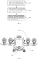
- FIG.2 is a schematic diagram of a wall-climbing robot provided in the embodiment.
- the thrust control method includes: acquiring an attitude direction of a body 100 first, where the attitude direction includes an angle of the body 100 on a vertical plane, and calculating a first included angle between the attitude direction and a direction of gravity of the body 100; rotating a rotating duct 200 according to a value of the first included angle, adjusting a thrust direction of the rotating duct 200 to make the thrust direction opposite to the direction of gravity of the body 100; acquiring thrust data measured by the first pressure sensor, adjusting a rotating speed of a fan in the rotating duct 200 according to the thrust data to make the thrust data equal to a value of gravity of the body 100, and controlling the direction and thrust of the rotating duct 200 to keep the thrust of the rotating duct 200 opposite to the gravity of the robot body 100 in direction and equal to the gravity of the robot body 100 in magnitude in real time, so that the robot can be stably suspended on the wall.
- the rotating duct 200 is fixed on the robot body 100.
- the rotating duct 200 rotates around an axis, that is, the rotating duct 200 is fixed on the body 100.
- a load-bearing frame is arranged on the body 100, the load-bearing frame is of a linear type, the rotating duct 200 is fixed on the linear load-bearing frame, and there are a plurality of rotating ducts 200.
- there are four rotating ducts 200 which are symmetrically arranged on both sides of the center of gravity of the robot body 100, that is, two rotating ducts 200 are arranged on the left side, and two rotating ducts 200 are arranged on the right side.
- the rotation direction of the rotating ducts 200 is perpendicular to the axis of the load-bearing frame.
- the axis of the load-bearing frame is parallel to a direction in which the robot advances in the horizontal direction.
- the axis of the load-bearing frame is in the horizontal direction.
- the attitude direction of the robot body 100 is acquired.
- the attitude direction is acquired by comparing the current attitude direction of the body 100 with the reference initial attitude direction.
- the initial attitude direction is an attitude direction of the robot, which is measured by a gyroscope installed in the body 100 when the robot is placed on a level ground.
- the change of the attitude direction of the robot on the curved surface may be calculated according to the initial attitude direction.
- the first included angle between the attitude direction and the direction of gravity of the body 100 can be calculated according to the included angle between the initial attitude direction and the direction of gravity. It can be understood that the pitch angle of the robot is detected by the gyroscope, the first included angle between the attitude direction and the direction of gravity of the body 100 is calculated according to the pitch angle. Since the rotating duct 200 is also fixed on the robot body 100, the rotating duct 200 has the same change according to the change of the attitude direction of the robot body 100.
- the rotating duct 200 is rotated by the same angle in the direction opposite to the direction in which the attitude of the body 100 changes, so that the wind outlet direction of the rotating duct 200 is the same as the direction of gravity, that is, the thrust direction of the rotating duct 200 is opposite to the direction of gravity.
- the first pressure sensor is arranged at a position where the robot body 100 is connected to the rotating duct 200, and may detect a pressure between the rotating duct 200 and the body 100 in real time. Therefore, according to the thrust data monitored by the first pressure sensor, the real-time thrust of the rotating duct 200 can be known, the gravity of the robot may be a preset value, or a real-time measured value. The thrust of the rotating duct 200 is adjusted, so that the thrust is opposite to the gravity in direction, and equal to the gravity in magnitude.
- the wall-climbing robot further includes an acceleration sensor configured to acquire an acceleration of the body 100, a direction of the acceleration of the body 100 is acquired through the acceleration sensor, and a second included angle between a component of the acceleration in a vertical direction and the direction of gravity of the body 100 is calculated.
- the rotating speed of the fan in the rotating duct 200 is adjusted according to the second included angle, so that a value of the acceleration in the vertical direction is zero.
- the acceleration sensor may detect that the attitude of the robot is abnormal.
- the second included angle between the component of the acceleration obtained by the acceleration sensor in the vertical direction and the direction of gravity, it can be determined whether the robot is in an abnormal motion state or not according to the change of the second included angle.
- the value of the acceleration measured by the acceleration sensor is not zero, and the value of the acceleration in the vertical direction is controlled to be zero by reversely controlling the rotating speed of the fan in the rotating duct 200.
- the vertical direction may be understood as a direction in a straight line with the direction of gravity.
- the rotating speed of the fan in the rotating duct 200 is adjusted according to the second included angle, so that the value of the acceleration in the vertical direction is zero.
- the second included angle is 0 degree
- the rotating speed of the fan in the rotating duct 200 is increased, so that the value of the acceleration in the vertical direction is zero.
- the second included angle is 180 degrees
- the rotating speed of the fan in the rotating duct is decreased, so that the value of the acceleration in the vertical direction is zero.
- the second included angle is 0 degree, that is, the direction of acceleration is the same as the direction of gravity of the robot, that is, the robot is suddenly falling downwards.
- the rotating speed of the fan in the rotating duct 200 it is necessary to increase the rotating speed of the fan in the rotating duct 200 and increase the magnitude of a thrust of the rotating duct 200.
- the thrust is used to resist the tendency of the robot to fall rapidly, so that the falling speed of the robot is slowed down gradually, and the value of the acceleration in the vertical direction is gradually reduced to zero.
- the second included angle is 180 degrees, that is, the direction of the acceleration is opposite to the direction of the gravity of the robot, that is, since the thrust of the rotating duct 200 is too large, the robot is flying up.
- the wall-climbing robot further includes at least one fixed duct 300 configured to provide a pressure and a second pressure sensor configured to acquire pressure data.
- the rotating speed of the fan in the rotating duct 200 is adjusted according to the second included angle to acquire pressure data.
- the second included angle is 0 degree
- the rotating speed of the fan in the fixed duct 300 is increased, so that the value of the acceleration in the vertical direction is zero.
- the second included angle is 180 degrees
- the rotation of the fan in the fixed duct 300 is stopped.
- at least one fixed duct 300 is arranged on the robot body 100.
- there are two fixed ducts 300 which are symmetrically arranged at both ends of the center of gravity of the robot body 100.
- the second pressure sensor is arranged at a position where the robot body 100 is connected with the fixed duct 300, and may detect the pressure of the fixed duct 300 on the body 100 in real time. Therefore, in the embodiment, when the second included angle is 0 degree, that is, the robot falls down unexpectedly and quickly, it is necessary to start the emergency mode to increase the rotating speed of the fan in the fixed duct 300.
- the pressure of the fixed duct 300 on the body 100 is increased, so that the robot is adsorbed on the wall.
- the friction force between the wall and the robot is increased, and the falling tendency of the robot is slowed down.
- the thrust data corresponding to a plurality of first pressure sensors is acquired; vector calculation is performed on the plurality of thrust data to acquire the value and direction of the thrust resultant force of the plurality of thrust data.
- the rotating speeds of the fans in a plurality of rotating ducts 200 are adjusted. Since the plurality of rotating ducts 200 are fixed to the robot body 100, the plurality of rotating ducts 200 generate a plurality of thrusts.
- vector calculation is performed on the plurality of thrusts.
- the rotating ducts 200 are symmetrically arranged on both sides of the center of gravity of the body 100, so that the thrust resultant force is the accumulation of the plurality of thrusts.
- the rotating speeds of the fans in the plurality of rotating ducts 200 are adjusted to acquire preset installation moment arms corresponding to the plurality of rotating ducts 200.
- the magnitudes of the thrusts corresponding to the plurality of rotating ducts 200 are calculated by using the installation moment arms.
- the rotating speeds of the fans are adjusted, so that the thrust data reaches the calculated magnitudes of the thrusts corresponding to the plurality of rotating duct 200.
- a plurality of rotating ducts 200 are fixedly installed on the robot body 100 to generate a plurality of thrusts, it is necessary to perform vector calculation on the plurality of thrusts.
- the thrusts are symmetrically distributed on both sides of the center of gravity of the robot, it is only necessary to make the rotating ducts 200 have the same thrust, and at the same time, to adjust equally the thrust value of each rotating duct 200, so that the thrust resultant force of the rotating ducts 200 is equal to the gravity of the robot.
- the installation moment arms corresponding to the plurality of rotating ducts 200 are arranged symmetrically and equally along the center of gravity of the body 100. Specifically, the plurality of rotating ducts 200 are symmetrically arranged on both sides of the center of gravity of the robot, and the distances between the rotating ducts are equal. This installation method can simplify the calculation of the thrust and reduce the complexity and difficulty of the algorithm control.
- the included angle between the component of the attitude direction of the body 100 in the horizontal direction and the horizontal line is calculated, and the rotating speed of the fan in the rotating duct 200 is adjusted according to the included angle in the horizontal direction, so that the plurality of rotating ducts 200 are on the same horizontal line.
- the rotating ducts 200 installed on the load-bearing frame are not balanced on the horizontal line, resulting in that the attitude of the robot will be inclined.
- the rotating speed of the fan in the rotating duct 200 may be adjusted in real time, and the thrust is adjusted in real time according to the real-time change of the robot, so that the robot can be kept stably suspended at any position on the arched wall of the tunnel to ensure the precise measurement requirements of the robot.
- the orientation of the rotating duct 200 may be adjusted in real time, that is, the thrust direction of the rotating duct 200 may be adjusted, and the thrust direction is adjusted in real time according to the real-time change of the attitude of the robot, so that the thrust direction of the rotating duct 200 is always opposite to the direction of gravity of the robot, and the magnitude of thrust is always equal to that of gravity, which enables the robot to be kept suspended at any position on the arched wall of the tunnel to ensure the precise measurement requirements of the robot.
Landscapes
- Engineering & Computer Science (AREA)
- Mechanical Engineering (AREA)
- Aviation & Aerospace Engineering (AREA)
- Radar, Positioning & Navigation (AREA)
- Combustion & Propulsion (AREA)
- Transportation (AREA)
- Chemical & Material Sciences (AREA)
- Remote Sensing (AREA)
- Physics & Mathematics (AREA)
- General Physics & Mathematics (AREA)
- Automation & Control Theory (AREA)
- Structures Of Non-Positive Displacement Pumps (AREA)
- Manipulator (AREA)
Applications Claiming Priority (1)
| Application Number | Priority Date | Filing Date | Title |
|---|---|---|---|
| CN202211136590.1A CN115230839B (zh) | 2022-09-19 | 2022-09-19 | 爬壁机器人推力控制方法 |
Publications (3)
| Publication Number | Publication Date |
|---|---|
| EP4339728A1 true EP4339728A1 (de) | 2024-03-20 |
| EP4339728B1 EP4339728B1 (de) | 2025-02-12 |
| EP4339728C0 EP4339728C0 (de) | 2025-02-12 |
Family
ID=83681966
Family Applications (1)
| Application Number | Title | Priority Date | Filing Date |
|---|---|---|---|
| EP23197966.7A Active EP4339728B1 (de) | 2022-09-19 | 2023-09-18 | Schubsteuerungsverfahren für einen wandkletterroboter |
Country Status (2)
| Country | Link |
|---|---|
| EP (1) | EP4339728B1 (de) |
| CN (1) | CN115230839B (de) |
Cited By (2)
| Publication number | Priority date | Publication date | Assignee | Title |
|---|---|---|---|---|
| CN120064437A (zh) * | 2025-02-25 | 2025-05-30 | 哈尔滨工程大学 | 大型压力容器自动检测机器人 |
| CN120213940A (zh) * | 2025-03-25 | 2025-06-27 | 广州大学 | 一种水下桥梁桩基损伤检测装置及方法 |
Families Citing this family (1)
| Publication number | Priority date | Publication date | Assignee | Title |
|---|---|---|---|---|
| CN118625848B (zh) * | 2024-08-14 | 2024-11-05 | 河北工业大学 | 一种机器人控制方法 |
Citations (4)
| Publication number | Priority date | Publication date | Assignee | Title |
|---|---|---|---|---|
| CN207207653U (zh) * | 2017-09-14 | 2018-04-10 | 王志成 | 基于四旋翼结构的爬墙机器人 |
| EP2734343B1 (de) * | 2011-07-18 | 2022-02-23 | The Boeing Company | Bewegliche Plattform |
| CN114801615A (zh) * | 2022-05-20 | 2022-07-29 | 西安交通大学 | 矢量推力式机器人 |
| CN115027191A (zh) * | 2022-06-22 | 2022-09-09 | 河海大学 | 一种可爬壁的多栖机器人 |
Family Cites Families (9)
| Publication number | Priority date | Publication date | Assignee | Title |
|---|---|---|---|---|
| US9233748B2 (en) * | 2012-01-04 | 2016-01-12 | James William McIntee | Roadable, adaptable-modular, multiphibious-amphibious ground effect or flying, car-boat-plane or surface-effect motorcycle |
| CN103721421A (zh) * | 2012-10-16 | 2014-04-16 | 田瑜 | 多旋翼飞行器 |
| EP2738091B1 (de) * | 2012-11-30 | 2015-07-22 | AIRBUS HELICOPTERS DEUTSCHLAND GmbH | Senkrecht startendes bzw. landendes (VTOL) Luftfahrzeug und Verfahren für den Betrieb eines solchen Luftfahrzeugs |
| US10605339B2 (en) * | 2016-02-26 | 2020-03-31 | Mitsubishi Heavy Industries Compressor Corporation | Variable speed accelerator and control method for variable speed accelerator |
| CN109624629B (zh) * | 2019-02-15 | 2020-11-13 | 苏州融萃特种机器人有限公司 | 基于矢量飞行的爬壁机器人 |
| CN112140821B (zh) * | 2020-10-13 | 2024-07-26 | 北京理工大学 | 一种陆空两用多模态涵道式飞行器及其控制方法 |
| CN112937713B (zh) * | 2021-04-02 | 2022-08-23 | 中南大学 | 复合型爬壁机器人及其控制方法 |
| CN113220009B (zh) * | 2021-07-08 | 2021-09-21 | 中国铁路设计集团有限公司 | 一种隧道衬砌检测用正压式爬壁机器人及其控制方法 |
| CN113602462B (zh) * | 2021-10-08 | 2022-09-23 | 南京工程学院 | 水下机器人及其水中高可视度情况下姿态与运动控制方法 |
-
2022
- 2022-09-19 CN CN202211136590.1A patent/CN115230839B/zh active Active
-
2023
- 2023-09-18 EP EP23197966.7A patent/EP4339728B1/de active Active
Patent Citations (4)
| Publication number | Priority date | Publication date | Assignee | Title |
|---|---|---|---|---|
| EP2734343B1 (de) * | 2011-07-18 | 2022-02-23 | The Boeing Company | Bewegliche Plattform |
| CN207207653U (zh) * | 2017-09-14 | 2018-04-10 | 王志成 | 基于四旋翼结构的爬墙机器人 |
| CN114801615A (zh) * | 2022-05-20 | 2022-07-29 | 西安交通大学 | 矢量推力式机器人 |
| CN115027191A (zh) * | 2022-06-22 | 2022-09-09 | 河海大学 | 一种可爬壁的多栖机器人 |
Cited By (2)
| Publication number | Priority date | Publication date | Assignee | Title |
|---|---|---|---|---|
| CN120064437A (zh) * | 2025-02-25 | 2025-05-30 | 哈尔滨工程大学 | 大型压力容器自动检测机器人 |
| CN120213940A (zh) * | 2025-03-25 | 2025-06-27 | 广州大学 | 一种水下桥梁桩基损伤检测装置及方法 |
Also Published As
| Publication number | Publication date |
|---|---|
| CN115230839A (zh) | 2022-10-25 |
| CN115230839B (zh) | 2023-01-17 |
| EP4339728B1 (de) | 2025-02-12 |
| EP4339728C0 (de) | 2025-02-12 |
Similar Documents
| Publication | Publication Date | Title |
|---|---|---|
| EP4339728B1 (de) | Schubsteuerungsverfahren für einen wandkletterroboter | |
| CN109720609B (zh) | 一种悬吊式微重力模拟装置及控制方法 | |
| US6496765B1 (en) | Control system and method for payload control in mobile platform cranes | |
| CN112415086B (zh) | 一种基于遥操作飞行机械臂的高空金属管道探伤系统 | |
| Yoo et al. | Position-tracking control of dual-rope winch robot with rope slip compensation | |
| CN105974797A (zh) | 考虑弹性影响与补偿的绳牵引并联机器人运动控制方法 | |
| US6343243B1 (en) | Method for determining load parameters for a manipulator | |
| US20240173858A1 (en) | Force-Controlled Handling Apparatus for Robot-Assisted Surface Machining | |
| CN115489632B (zh) | 爬壁机器人压力控制方法 | |
| WO2018180646A1 (ja) | クレーンの制御システム及び制御方法 | |
| CN114603603A (zh) | 空间机械臂在轨操作的地面模拟装置及模拟方法 | |
| Hamaza et al. | 2d contour following with an unmanned aerial manipulator: Towards tactile-based aerial navigation | |
| CN115755590A (zh) | 一种高超声速飞行器抗扰制导控制系统及方法 | |
| Tanaka et al. | Motion control of a wall climbing robot with coaxial propeller thruster | |
| CN120621525A (zh) | 磁吸附式旋翼无人车的工作面吸附及脱附控制方法及系统 | |
| JP4617990B2 (ja) | 自動飛行制御装置、自動飛行制御方法及び自動飛行制御プログラム | |
| CN112987592A (zh) | 一种三轴气浮台控制过程中的动态调平系统及动态调平方法 | |
| CN119440077A (zh) | 一种基于辅助喷气的四足机器人控制方法 | |
| CN115305979B (zh) | 用于控制工程设备臂架的方法、处理器、装置及工程设备 | |
| JPH0428509B2 (de) | ||
| CN111459177A (zh) | 一种用于水面漂浮的三轴稳定平台的稳定控制方法 | |
| US12545428B2 (en) | Electric propulsion system control device | |
| CN110775819B (zh) | 一种塔式起重机防摇摆控制方法及系统 | |
| CN111099040B (zh) | 一种基于控制力矩陀螺群控制的系统极性确定方法 | |
| JP2772883B2 (ja) | クレーンの振れ止め・位置決め制御装置及び制御方法 |
Legal Events
| Date | Code | Title | Description |
|---|---|---|---|
| PUAI | Public reference made under article 153(3) epc to a published international application that has entered the european phase |
Free format text: ORIGINAL CODE: 0009012 |
|
| STAA | Information on the status of an ep patent application or granted ep patent |
Free format text: STATUS: REQUEST FOR EXAMINATION WAS MADE |
|
| 17P | Request for examination filed |
Effective date: 20230922 |
|
| AK | Designated contracting states |
Kind code of ref document: A1 Designated state(s): AL AT BE BG CH CY CZ DE DK EE ES FI FR GB GR HR HU IE IS IT LI LT LU LV MC ME MK MT NL NO PL PT RO RS SE SI SK SM TR |
|
| GRAP | Despatch of communication of intention to grant a patent |
Free format text: ORIGINAL CODE: EPIDOSNIGR1 |
|
| STAA | Information on the status of an ep patent application or granted ep patent |
Free format text: STATUS: GRANT OF PATENT IS INTENDED |
|
| INTG | Intention to grant announced |
Effective date: 20241028 |
|
| GRAS | Grant fee paid |
Free format text: ORIGINAL CODE: EPIDOSNIGR3 |
|
| GRAA | (expected) grant |
Free format text: ORIGINAL CODE: 0009210 |
|
| STAA | Information on the status of an ep patent application or granted ep patent |
Free format text: STATUS: THE PATENT HAS BEEN GRANTED |
|
| AK | Designated contracting states |
Kind code of ref document: B1 Designated state(s): AL AT BE BG CH CY CZ DE DK EE ES FI FR GB GR HR HU IE IS IT LI LT LU LV MC ME MK MT NL NO PL PT RO RS SE SI SK SM TR |
|
| REG | Reference to a national code |
Ref country code: GB Ref legal event code: FG4D |
|
| REG | Reference to a national code |
Ref country code: CH Ref legal event code: EP |
|
| REG | Reference to a national code |
Ref country code: DE Ref legal event code: R096 Ref document number: 602023002004 Country of ref document: DE |
|
| REG | Reference to a national code |
Ref country code: IE Ref legal event code: FG4D |
|
| U01 | Request for unitary effect filed |
Effective date: 20250303 |
|
| U07 | Unitary effect registered |
Designated state(s): AT BE BG DE DK EE FI FR IT LT LU LV MT NL PT RO SE SI Effective date: 20250311 |
|
| PG25 | Lapsed in a contracting state [announced via postgrant information from national office to epo] |
Ref country code: RS Free format text: LAPSE BECAUSE OF FAILURE TO SUBMIT A TRANSLATION OF THE DESCRIPTION OR TO PAY THE FEE WITHIN THE PRESCRIBED TIME-LIMIT Effective date: 20250512 |
|
| PG25 | Lapsed in a contracting state [announced via postgrant information from national office to epo] |
Ref country code: PL Free format text: LAPSE BECAUSE OF FAILURE TO SUBMIT A TRANSLATION OF THE DESCRIPTION OR TO PAY THE FEE WITHIN THE PRESCRIBED TIME-LIMIT Effective date: 20250212 |
|
| PG25 | Lapsed in a contracting state [announced via postgrant information from national office to epo] |
Ref country code: ES Free format text: LAPSE BECAUSE OF FAILURE TO SUBMIT A TRANSLATION OF THE DESCRIPTION OR TO PAY THE FEE WITHIN THE PRESCRIBED TIME-LIMIT Effective date: 20250212 |
|
| PG25 | Lapsed in a contracting state [announced via postgrant information from national office to epo] |
Ref country code: IS Free format text: LAPSE BECAUSE OF FAILURE TO SUBMIT A TRANSLATION OF THE DESCRIPTION OR TO PAY THE FEE WITHIN THE PRESCRIBED TIME-LIMIT Effective date: 20250612 Ref country code: NO Free format text: LAPSE BECAUSE OF FAILURE TO SUBMIT A TRANSLATION OF THE DESCRIPTION OR TO PAY THE FEE WITHIN THE PRESCRIBED TIME-LIMIT Effective date: 20250512 |
|
| PG25 | Lapsed in a contracting state [announced via postgrant information from national office to epo] |
Ref country code: HR Free format text: LAPSE BECAUSE OF FAILURE TO SUBMIT A TRANSLATION OF THE DESCRIPTION OR TO PAY THE FEE WITHIN THE PRESCRIBED TIME-LIMIT Effective date: 20250212 |
|
| PG25 | Lapsed in a contracting state [announced via postgrant information from national office to epo] |
Ref country code: GR Free format text: LAPSE BECAUSE OF FAILURE TO SUBMIT A TRANSLATION OF THE DESCRIPTION OR TO PAY THE FEE WITHIN THE PRESCRIBED TIME-LIMIT Effective date: 20250513 |
|
| U20 | Renewal fee for the european patent with unitary effect paid |
Year of fee payment: 3 Effective date: 20250807 |
|
| PG25 | Lapsed in a contracting state [announced via postgrant information from national office to epo] |
Ref country code: SM Free format text: LAPSE BECAUSE OF FAILURE TO SUBMIT A TRANSLATION OF THE DESCRIPTION OR TO PAY THE FEE WITHIN THE PRESCRIBED TIME-LIMIT Effective date: 20250212 |
|
| PG25 | Lapsed in a contracting state [announced via postgrant information from national office to epo] |
Ref country code: CZ Free format text: LAPSE BECAUSE OF FAILURE TO SUBMIT A TRANSLATION OF THE DESCRIPTION OR TO PAY THE FEE WITHIN THE PRESCRIBED TIME-LIMIT Effective date: 20250212 |
|
| PG25 | Lapsed in a contracting state [announced via postgrant information from national office to epo] |
Ref country code: SK Free format text: LAPSE BECAUSE OF FAILURE TO SUBMIT A TRANSLATION OF THE DESCRIPTION OR TO PAY THE FEE WITHIN THE PRESCRIBED TIME-LIMIT Effective date: 20250212 |
|
| PLBE | No opposition filed within time limit |
Free format text: ORIGINAL CODE: 0009261 |
|
| STAA | Information on the status of an ep patent application or granted ep patent |
Free format text: STATUS: NO OPPOSITION FILED WITHIN TIME LIMIT |
|
| 26N | No opposition filed |
Effective date: 20251113 |
|
| U1N | Appointed representative for the unitary patent procedure changed after the registration of the unitary effect |
Representative=s name: MARKS & CLERK LLP; GB |