EP4339737A1 - Serverschrank und server - Google Patents
Serverschrank und server Download PDFInfo
- Publication number
- EP4339737A1 EP4339737A1 EP22857575.9A EP22857575A EP4339737A1 EP 4339737 A1 EP4339737 A1 EP 4339737A1 EP 22857575 A EP22857575 A EP 22857575A EP 4339737 A1 EP4339737 A1 EP 4339737A1
- Authority
- EP
- European Patent Office
- Prior art keywords
- plate
- fan
- support
- server chassis
- chassis according
- Prior art date
- Legal status (The legal status is an assumption and is not a legal conclusion. Google has not performed a legal analysis and makes no representation as to the accuracy of the status listed.)
- Pending
Links
Images


Classifications
-
- G—PHYSICS
- G06—COMPUTING OR CALCULATING; COUNTING
- G06F—ELECTRIC DIGITAL DATA PROCESSING
- G06F1/00—Details not covered by groups G06F3/00 - G06F13/00 and G06F21/00
- G06F1/16—Constructional details or arrangements
- G06F1/18—Packaging or power distribution
-
- G—PHYSICS
- G06—COMPUTING OR CALCULATING; COUNTING
- G06F—ELECTRIC DIGITAL DATA PROCESSING
- G06F1/00—Details not covered by groups G06F3/00 - G06F13/00 and G06F21/00
- G06F1/16—Constructional details or arrangements
- G06F1/20—Cooling means
-
- H—ELECTRICITY
- H05—ELECTRIC TECHNIQUES NOT OTHERWISE PROVIDED FOR
- H05K—PRINTED CIRCUITS; CASINGS OR CONSTRUCTIONAL DETAILS OF ELECTRIC APPARATUS; MANUFACTURE OF ASSEMBLAGES OF ELECTRICAL COMPONENTS
- H05K7/00—Constructional details common to different types of electric apparatus
- H05K7/20—Modifications to facilitate cooling, ventilating, or heating
- H05K7/20009—Modifications to facilitate cooling, ventilating, or heating using a gaseous coolant in electronic enclosures
- H05K7/20136—Forced ventilation, e.g. by fans
- H05K7/20172—Fan mounting or fan specifications
-
- H—ELECTRICITY
- H05—ELECTRIC TECHNIQUES NOT OTHERWISE PROVIDED FOR
- H05K—PRINTED CIRCUITS; CASINGS OR CONSTRUCTIONAL DETAILS OF ELECTRIC APPARATUS; MANUFACTURE OF ASSEMBLAGES OF ELECTRICAL COMPONENTS
- H05K7/00—Constructional details common to different types of electric apparatus
- H05K7/20—Modifications to facilitate cooling, ventilating, or heating
- H05K7/20009—Modifications to facilitate cooling, ventilating, or heating using a gaseous coolant in electronic enclosures
- H05K7/20209—Thermal management, e.g. fan control
-
- H—ELECTRICITY
- H05—ELECTRIC TECHNIQUES NOT OTHERWISE PROVIDED FOR
- H05K—PRINTED CIRCUITS; CASINGS OR CONSTRUCTIONAL DETAILS OF ELECTRIC APPARATUS; MANUFACTURE OF ASSEMBLAGES OF ELECTRICAL COMPONENTS
- H05K7/00—Constructional details common to different types of electric apparatus
- H05K7/20—Modifications to facilitate cooling, ventilating, or heating
- H05K7/20709—Modifications to facilitate cooling, ventilating, or heating for server racks or cabinets; for data centers, e.g. 19-inch computer racks
- H05K7/20718—Forced ventilation of a gaseous coolant
- H05K7/20727—Forced ventilation of a gaseous coolant within server blades for removing heat from heat source
Definitions
- the present disclosure relates to the field of server technologies, and specifically, to a server chassis and a server.
- a fan module in a server determines the heat dissipation performance of the server, and the heat dissipation capability is one of the important factors affecting the service life of the server.
- a fan support in the fan module is often fixed, resulting in that during assembly and maintaining of the fan module, the entire module cannot be assembled and disassembled, causing a complex disassembly and assembly process of the fan module and affecting the disassembly and assembly efficiency of the fan module.
- the present disclosure is intended to resolve one of technical problems in the related art at least to some extent.
- the present disclosure provides a server chassis.
- the server chassis includes a bottom case and a fan module.
- the bottom case includes a bottom plate, and the fan module is arranged in the bottom case.
- the fan module includes a fan support, multiple fan bodies, and a driving member.
- the fan support is provided with multiple accommodating cavities, and the multiple fan bodies are mounted in the multiple accommodating cavities.
- the driving member is rotatably connected to the fan support, and the driving member is adapted to drive the fan module to move relative to the bottom case in a direction perpendicular to the bottom plate.
- the fan module moves in and out of the bottom case through the driving member.
- support frames are arranged between two sides of the fan module and the bottom case, and independent winding spaces are formed between the support frames and side plates of the bottom case, so that the assembly of the fan module are not affected by wires and the assembly sequence is not limited.
- an elastic heat insulation member is arranged in the support frame, so that the winding spaces on two sides are not affected by the chassis configuration, thereby avoiding the problem of air flow reflux, and the heat insulation member made of an elastic material can be assembled and disassembled or assembled into the support frame without tools.
- the support frames on the two sides of the fan module are skillfully designed, so that materials are completely shared, and the types of materials are reduced, thereby reducing costs.
- the present disclosure further provides a server, the server including the foregoing server chassis.
- an embodiment of the present disclosure provides a server chassis, including a fan module 1 and a bottom case 2.
- the bottom case 2 includes two opposite side plates 21 and a bottom plate 22 connected to the two side plates 21.
- the fan module 1 is arranged in the bottom case 2.
- the fan module 1 includes a fan support 11, multiple fan bodies 12, and a driving member 13.
- the fan support 11 is provided with multiple accommodating cavities 113, and the multiple fan bodies 12 are mounted in the multiple accommodating cavities 113.
- the driving member 13 is rotatably connected to the fan support 11, and the driving member 13 is adapted to drive the fan module 1 to move relative to the bottom case 2 in a direction perpendicular to the bottom plate 22.
- the fan module 1 moves in and out of the bottom case 2 through the driving member 13.
- the multiple fan bodies 12 and the multiple accommodating cavities 113 are provided in a one-to-one correspondence, so that the structure is simple, thereby facilitating the mounting of the fan bodies.
- the driving member 13 drives the fan module 1 to move relative to the bottom case 2 in the direction perpendicular to the bottom plate 22, so that the fan module 1 moves in and out of the bottom case 2 under the action of the driving member 13, thereby achieving labor-saving assembly of the fan module 1 in the bottom case.
- a server mainboard 6 is further arranged in the server chassis.
- the fan body of the fan module has an end interface 7.
- the end interface 7 of the fan module is connected to a board end interface 61 of the server mainboard 6, to achieve power and signal conduction for the fan module.
- the driving member 13 includes two opposite side arms 131 and a middle handle 132 connecting the two side arms 131.
- the two side arms 131 are rotatably connected to the fan support 11.
- the side arm 131 includes a transmission portion 1311, and a transmission fitting member 3 adapted to the transmission portion 1311 is arranged in the bottom case 2.
- the side arms are riveted to the fan support through rivets and gaskets, and the middle handle and the two side arms are fixed through rivets.
- the driving member 13 of the fan module 1 is a handle.
- the transmission portion 1311 on the side arm 131 cooperates with the transmission fitting member 3 to rotate the driving member 13, so that the fan module moves in and out of the bottom case of the server chassis.
- the use of the middle handle 132 allows the two side arms 131 to rotate simultaneously, thereby realizing synchronous movement of transmission portions on the left side and the right side, and making the removal and disassembly of the fan module smoother; and the middle handle 132 facilitates the operator to rotate the driving member 13.
- the side arm 131 is parallel to the side plate 21 of the bottom case 2.
- two oppositely concave arc-shaped notch structures 1321 are arranged at the middle part of the middle handle 132.
- the arc-shaped notch structures 1321 are convenient for the operator to hold.
- the transmission portion 1311 is an incomplete gear
- the transmission fitting member 3 is a rack meshed with the incomplete gear
- the rack is a plate-shaped member
- a reference line of the rack is tangent to a reference circle of the incomplete gear, and the reference line of the rack is perpendicular to the bottom plate 22.
- the fan support 11 includes two opposite side vertical plates 111, the two side arms 131 are connected to the two side vertical plates 111 in a one-to-one correspondence, two stop positioning structures 4 are arranged on the side vertical plates 111, and the two stop positioning structures 4 are configured to limit angular ranges within which the side arms 131 are rotatable.
- the side vertical plate 111 is parallel to the side plate 21 of the bottom case 2, and the two stop positioning structures 4 limit the rotation of the side arm 131 between a first position and a second position.
- the fan module 1 At the first position, the fan module 1 is not mounted in the bottom case 2; and at the second position, the fan module 1 is mounted in the bottom case 2, and the end interface of the fan module is connected to the board end interface of the server mainboard.
- the stop positioning structure 4 includes a stop portion 41 and a positioning portion 42, and both the stop portion 41 and the positioning portion 42 protrude from the side vertical plate 111.
- the side arm 131 has an integrally formed structure, the side arm 131 further includes a body portion 1312 connected to the transmission portion 1311 and an overhanging portion 1313 connected to the body portion 1312, and the overhanging portion 1313 elastically abuts against the positioning portion 42.
- the stop portion 41 is an L-shaped stop piece or a stop convex point.
- the body portion 1312 is connected to the transmission portion 1311, and the overhanging portion 1313 protrudes from the body portion 1312.
- the overhanging portion 1313 is an L-shaped overhanging arm relative to the body portion 1312.
- the positioning portion 42 protrudes from the side vertical plate 111 and has a recessed portion concave toward the side vertical plate 11, and a recess depth of the recessed portion is less than a thickness of the positioning portion in a direction perpendicular to the side vertical plate.
- the overhanging portion 1312 is in elastic contact with the positioning portion 42, so that when the side arm 131 abuts against the corresponding stop portion 41, the side arm 131 can be relatively fixed (or locked), to prevent the side arm 131 from rotating randomly between the first position and the second position, thereby improving the reliability of the connection between the fan module 1 and the bottom case.
- the fan body 12 includes a fan and a fan cover body 121 that accommodates the fan.
- the fan cover body 121 includes a fan front cover 1211 and a fan rear cover 1212.
- the fan cover body 121 is provided with an elastic protrusion 1213 and a pair of corner notches 1214.
- the pair of corner notches 1214 is configured to facilitate the hand to grasp the fan body.
- the fan support 11 further includes multiple vertical plates 112 parallel to the side vertical plates 111.
- the multiple vertical plates 112 and the side vertical plates 111 are provided with clamping holes 114.
- the fan body 12 is clamped into the clamping hole 114 through the elastic protrusion 1213, thereby achieving fixation of the fan body 12 on the fan support 11.
- the manner in which the fan body 12 is clamped with the fan support 11 facilitates the disassembly of the fan body when the fan body fails.
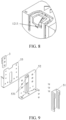
- two support frames 5 configured to mount the transmission fitting member 3 are arranged on the bottom plate 22, and the fan module 1 is arranged between the two support frames 5.
- the support frame 5 includes a support assembly and an elastic heat insulation member 51, the support assembly is fixedly connected to the bottom plate 22, and the support assembly has a vertical support portion perpendicular to the bottom plate 22. The vertical support portion is parallel to and spaced apart from the side plate 21.
- the elastic heat insulation member 51 is detachably connected to the vertical support portion, and the elastic heat insulation member 51 abuts against the side plate 21.
- the vertical support portion of the support frame 5 is spaced apart from the side plate 21 of the bottom case 2, the fan module and the support frame are assembled into the bottom case, and the support frames on two sides of the fan provide two independent winding spaces, so that assembly, disassembly, and replacement of the fan module and assembly, disassembly, and replacement of wires do not affect each other, and there is no limitation on the assembly sequence, which facilitates the assembly of the fan module.
- the detachable elastic heat insulation members prevent the winding spaces on two sides from being affected by the chassis configuration, and arrangement of the elastic heat insulation members in the winding space can effectively avoid heat reflux.
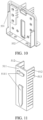
- the elastic heat insulation member 51 includes a connection plate 511 and at least one heat insulation plate 512, the connection plate 511 is parallelly attached to the vertical support portion, the heat insulation plate 512 is vertically connected to the connection plate 511, and both the heat insulation plate 512 and the connection plate 511 are perpendicular to the bottom plate 22; and the heat insulation plate 512 is provided with multiple spaced-apart gaps 513 in the direction perpendicular to the bottom plate 22.
- the heat insulation plate 512 prevents heat reflux downstream of the fan module in the winding space.
- the gaps 513 on the heat insulation plate 512 facilitate partial bending of the heat insulation plate, thereby facilitating wiring.
- the elastic heat insulation member 51 has an integrally formed structure, and the elastic heat insulation member 51 is a silicone heat insulation member or a rubber heat insulation member.
- the elastic heat insulation member can be assembled and disassembled on the vertical support portion without tools.
- the vertical support portion includes a first support plate 52 and a second support plate 53 arranged in parallel, the transmission fitting member 3 is arranged on the second support plate 53, and the transmission fitting member 3, the second support plate 53, and the first support plate 52 are riveted and fixed.
- the first support plate 52 is provided with a clamping groove 531, a buckle 5111 is arranged on the connection plate 511, and the buckle 5111 is clamped with the clamping groove 531.
- the second support plate 53 is provided with a yielding groove, and the yielding groove is configured to make space for the buckle on the connection plate, to facilitate the buckle on the connection plate 511 to be clamped with the clamping groove on the first support plate 52.
- the elastic heat insulation member is clamped with the clamping groove on the first support plate through the buckle, to facilitate the assembly of the elastic heat insulation member.
- the buckle has an L-shaped structure and protrudes from the connection plate.
- a T-shaped clamping groove is provided on the first support plate 52 to be clamped with the buckle.
- the T-shaped clamping groove facilitates the assembly of the buckle.
- Two buckles are arranged on the connection plate, and two clamping grooves are correspondingly provided on the first support plate, thereby improving the reliability of the connection between the elastic heat insulation member and the first support plate.
- a bottom portion of the first support plate 52 is connected to a base, and the base is provided with a riveting hole for riveting with the bottom plate of the bottom case, thereby realizing the fixation of the support frame on the bottom plate.
- an assembly guide structure 531 and a positioning guide structure 532 are respectively arranged on two opposite edges of the second support plate 53 on a side of the second support plate 53 facing away from the first support plate 52.
- a guiding structure 115 cooperating with the assembly guide structure 531 is arranged on the fan support 11, and the positioning guide structure 532 is configured to be slidably engaged with an outer surface of the fan support 11.
- the fan support 11 is docked with the support frame 5 through the assembly guide structure 531, and the fan support 11 is restricted through the positioning guide structure to assist the fan support 11 in being aligned with the support frame 5.
- the assembly guide structure 531 is a first guide plate
- the guiding structure 115 includes a guide groove structure connected to an edge of the side vertical plate 111, and the first guide plate is slidably connected to the guide groove structure.
- the positioning guide structure 532 is a second guide plate, and the second guide plate and the second support plate 53 are bent and connected at a right angle to be slidably connected to a corner of the fan support 11.
- the first guide plate of the support frame 5 is slidably connected to the guide groove structure of the fan support 11.
- the second guide plate and the second support plate are at a right angle to limit the position of the fan support 11, thereby ensuring that the fan module can be aligned with a region inside the bottom case, and realizing the connection between the end interface of the fan module and the board end interface of the server mainboard.
- support frames are provided on both of two sides of the fan module in the direction perpendicular to the side vertical plate.
- the first support plate and the second support plate in the support frame are respectively provided with riveting holes.
- the first support plate has a first axis perpendicular to the bottom plate, and the rivet holes on the first support plate are symmetrical with respect to the first axis.
- the second support plate has a second axis perpendicular to the bottom plate, and the riveting holes on the second support plate are symmetrical with respect to the second axis.
- riveting holes on the first support plate and riveting holes on the second support plate are in a one-to-one correspondence.
- the first support plate and the second support plate are riveted to the transmission fitting member (for example, a rack), so that the support assembly with the first support plate and the second support plate can be used on both of two sides of the fan module.
- the transmission fitting member for example, a rack
- the components of the support frames on the two sides of the fan module are in common use, thereby reducing the quantity of sets of molds and effectively reducing development costs.
- the first axis and the second axis are virtual structures introduced to facilitate the introduction of the arrangement form of the riveting holes.
- the side arms and the middle handle are connected to form a driving member, and the driving member is connected to the fan support.
- the fan body is clamped into the fan, to form a fan module.
- the rack is mounted on the support frame, and the support frame is mounted into the bottom case.
- the fan module is mounted into the bottom case.
- each of the middle handle 132 and the side arms 131 has a plate-shaped structure.
- the side arm is parallel to the side vertical plate 111 of the fan support.
- a plane on which the middle handle 132 is located is perpendicular to a plane on which the side arm 131 are located.
- the driving member formed by the middle handle and the side arms is lifted under force, the driving member is limited to rotate within a range of 90° between the two stop positioning structures.
- the side arm 131 is at the first position
- the middle handle 132 is perpendicular to the bottom plate 22 of the bottom case 2
- the incomplete gear and the rack are in a first meshing state.
- the incomplete gear and the rack are exactly in contact and meshed
- the teeth of the incomplete gear and the teeth of the rack are not cross-meshed
- the fan module has not been mounted into the bottom case.
- the middle handle 132 is located above the fan support 11, and the fan support is aligned with the assembly guide structure and the positioning guide structure on the support frame in terms of positions.
- the side arm 131 is at the second position, the middle handle 132 is parallel to the bottom plate 22 of the bottom case 2, the middle handle 132 is located on a side portion of the fan support 11, and the incomplete gear and the rack are in a second meshing state. In the second meshing state, the teeth of the incomplete gear are cross-meshed with the teeth of the rack.
- the incomplete gear and the rack are switched from the first meshing state to the second meshing state.
- the rotation of the incomplete gear drives the fan module to move toward the bottom plate in the direction perpendicular to the bottom plate until the end interface of the fan module is connected to the board end interface of the server mainboard, thereby realizing the power and signal conduction of the fan module.
- FIG. 17 For a position of the end interface of the fan body and a position of the board end interface of the server mainboard, reference may be made to FIG. 17 .
- a bottom portion of the fan body faces upward to illustrate the position of the end interface.
- parameter settings of the incomplete gear and the rack may be preferably as follows. Through the meshing between the incomplete gear and the rack, the fan module can move in the direction perpendicular to the bottom plate.
- parameters of the incomplete gear are as follows:
- parameters of the rack are as follows:
- the driving member rotates 90° in the counterclockwise direction, that is, the incomplete gear rotates 90°.
- the fan module is driven to move downward in a direction parallel to the rack (that is, the direction perpendicular to the bottom plate).
- the driving member rotates 90° clockwise, and the fan module moves upward by 25.12 mm in the direction perpendicular to the bottom plate.
- an embodiment of the present disclosure provides a server, including the foregoing server chassis, and further including components such as a CPU heat sink and a memory module.
- first, second, and the like are used in the present disclosure to describe various information, the information should not be limited to these terms. These terms are merely used to distinguish between information of the same type.
- first information may also be referred to as second information, and similarly, second information may also be referred to as first information.
- orientation or position relationships indicated by terms such as “center”, “longitudinal”, “transverse”, “length”, “width”, “thickness”, “upper”, “lower”, “front”, “rear”, “left”, “right”, “vertical”, “horizontal”, “top”, “bottom”, “inner”, “outer”, “clockwise”, “counterclockwise”, “axial”, “radial”, and “circumferential” are orientation or position relationship shown based on the accompanying drawings, and are merely used for describing the present disclosure and simplifying the description, rather than indicating or implying that the mentioned apparatus or element should have a particular orientation or be constructed and operated in a particular orientation, and therefore, should not be construed as a limitation to the present disclosure.
- first and second are used for descriptive purposes only and are not to be construed as indicating or implying relative importance or implicitly indicating the quantity of technical features indicated. Therefore, a feature limited by “first” or “second” may explicitly or implicitly include one or more of the features.
- a plurality of means two or more unless it is specifically defined otherwise.
- the terms such as “mounting”, “connected”, “connection”, and “fixed” are to be construed broadly, for example, as fixed connection, detachable connection or integral connection, as mechanical connection or electrical connection, and as direct connection or indirect connection via an intermediary or communication inside two elements or interaction between two elements.
- a first feature "on” or “under” a second feature may be the first feature in direct contact with the second feature, or the first feature in indirect contact with the second feature by using an intermediate medium.
- the first feature is “above”, “over”, or “on” the second feature may indicate that the first feature is directly above or obliquely above the second feature, or may merely indicate that a horizontal height of the first feature is higher than that of the second feature.
- That the first feature is "below”, “under”, and “beneath” the second feature may indicate that the first feature is directly below or obliquely below the second feature, or may merely indicate that the horizontal height of the first feature is lower than that of the second feature.
Landscapes
- Engineering & Computer Science (AREA)
- Microelectronics & Electronic Packaging (AREA)
- Physics & Mathematics (AREA)
- Thermal Sciences (AREA)
- General Engineering & Computer Science (AREA)
- Theoretical Computer Science (AREA)
- Computer Hardware Design (AREA)
- Human Computer Interaction (AREA)
- General Physics & Mathematics (AREA)
- Power Engineering (AREA)
- Cooling Or The Like Of Electrical Apparatus (AREA)
- Preparation Of Compounds By Using Micro-Organisms (AREA)
- Devices For Dispensing Beverages (AREA)
Applications Claiming Priority (2)
| Application Number | Priority Date | Filing Date | Title |
|---|---|---|---|
| CN202121975919.4U CN216052881U (zh) | 2021-08-20 | 2021-08-20 | 服务器机箱及服务器 |
| PCT/CN2022/109113 WO2023020263A1 (zh) | 2021-08-20 | 2022-07-29 | 服务器机箱及服务器 |
Publications (2)
| Publication Number | Publication Date |
|---|---|
| EP4339737A1 true EP4339737A1 (de) | 2024-03-20 |
| EP4339737A4 EP4339737A4 (de) | 2024-11-20 |
Family
ID=80559884
Family Applications (1)
| Application Number | Title | Priority Date | Filing Date |
|---|---|---|---|
| EP22857575.9A Pending EP4339737A4 (de) | 2021-08-20 | 2022-07-29 | Serverschrank und server |
Country Status (6)
| Country | Link |
|---|---|
| US (1) | US12581615B2 (de) |
| EP (1) | EP4339737A4 (de) |
| CN (1) | CN216052881U (de) |
| CA (1) | CA3223409A1 (de) |
| TW (1) | TWM640397U (de) |
| WO (1) | WO2023020263A1 (de) |
Families Citing this family (13)
| Publication number | Priority date | Publication date | Assignee | Title |
|---|---|---|---|---|
| KR102915213B1 (ko) * | 2020-07-31 | 2026-01-20 | 엘지이노텍 주식회사 | 파워 모듈 |
| CN216052881U (zh) * | 2021-08-20 | 2022-03-15 | 比亚迪股份有限公司 | 服务器机箱及服务器 |
| CN115038308B (zh) * | 2022-06-23 | 2025-01-21 | 西安易朴通讯技术有限公司 | 风扇模组和电子设备 |
| CN115390638A (zh) * | 2022-09-13 | 2022-11-25 | 深圳华杉技术有限公司 | 安装模组、风扇模组及服务器 |
| TWI852091B (zh) * | 2022-09-21 | 2024-08-11 | 緯創資通股份有限公司 | 風扇架組件及包括其之電子裝置 |
| TWI861908B (zh) * | 2023-05-29 | 2024-11-11 | 勤誠興業股份有限公司 | 伺服器裝置及其伺服器機殼 |
| CN116583093B (zh) * | 2023-07-11 | 2023-10-13 | 西安图为电气技术有限公司 | 具有风扇面板的电源模块 |
| TWI881511B (zh) * | 2023-10-27 | 2025-04-21 | 新加坡商鴻運科股份有限公司 | 風扇模組及電子設備 |
| US12495514B2 (en) | 2023-10-27 | 2025-12-09 | Nanning Fulian Fugui Precision Industrial Co., Ltd. | Fan assembly and electronic device |
| CN121050542A (zh) * | 2024-05-30 | 2025-12-02 | 纬联电子科技(中山)有限公司 | 电子装置及缓冲机构 |
| CN118764734A (zh) * | 2024-07-31 | 2024-10-11 | 中国电信股份有限公司 | 无线基站 |
| CN119403074A (zh) * | 2024-12-31 | 2025-02-07 | 成都红芯源电子科技有限公司 | 一种高功率大电流输出的隔离电源模块 |
| CN121433453B (zh) * | 2025-12-30 | 2026-04-21 | 苏州元脑智能科技有限公司 | 框架结构、散热装置及服务器 |
Family Cites Families (22)
| Publication number | Priority date | Publication date | Assignee | Title |
|---|---|---|---|---|
| US6556437B1 (en) * | 2000-08-10 | 2003-04-29 | Dell Products L.P. | Ergonomic carrier for hot-swap computer components |
| US6603661B2 (en) * | 2001-12-14 | 2003-08-05 | Hewlett-Packard Development Company, L.P. | Universal fan cage for hot-pluggable fans |
| US7021895B2 (en) * | 2002-11-13 | 2006-04-04 | Hewlett-Packard Development Company, L.P. | Fan module with integrated diffuser |
| US6839233B2 (en) * | 2003-01-02 | 2005-01-04 | Dell Products L.P. | Removable fan bay |
| US7920384B2 (en) * | 2005-08-09 | 2011-04-05 | Hewlett-Packard Development Company, L.P. | Fan cage for computer systems |
| CN2836081Y (zh) * | 2005-10-10 | 2006-11-08 | 英业达股份有限公司 | 散热机构 |
| CN100578021C (zh) * | 2006-11-28 | 2010-01-06 | 英业达股份有限公司 | 风扇固定结构 |
| US20090195978A1 (en) * | 2008-02-05 | 2009-08-06 | Inventec Corporation | Structure and method for electrically connecting heat dissipating device and adapting circuit board |
| US7771218B2 (en) * | 2008-05-05 | 2010-08-10 | Dell Products L.P. | Electrical coupler mating system |
| US7675747B1 (en) * | 2008-12-10 | 2010-03-09 | Sun Microsystems, Inc. | Reversible, counter-rotating fan modules for a computer chassis |
| US8300404B2 (en) * | 2010-04-15 | 2012-10-30 | Hewlett-Packard Development Company, L.P. | Fan holder including cable channels |
| CN201749408U (zh) | 2010-04-23 | 2011-02-16 | 环达电脑(上海)有限公司 | 免工具拆装的风扇架 |
| US8279596B2 (en) * | 2010-07-29 | 2012-10-02 | Dell Products L.P. | Fan mounting system |
| CN102541215B (zh) * | 2010-12-10 | 2016-06-01 | 中山市云创知识产权服务有限公司 | 风扇固定装置 |
| CN102841649A (zh) * | 2011-06-23 | 2012-12-26 | 鸿富锦精密工业(深圳)有限公司 | 风扇模组固定装置 |
| CN102999129B (zh) * | 2011-09-09 | 2015-06-17 | 英业达股份有限公司 | 风扇单元总成 |
| TW201328478A (zh) * | 2011-12-20 | 2013-07-01 | Inventec Corp | 伺服器 |
| CN107704057B (zh) * | 2017-10-23 | 2020-12-04 | 西安易朴通讯技术有限公司 | 一种风扇模组和电子装置 |
| CN111142625B (zh) * | 2018-11-05 | 2021-08-24 | 纬联电子科技(中山)有限公司 | 固定架组与服务器 |
| US11690190B2 (en) * | 2021-04-26 | 2023-06-27 | Quanta Computer Inc. | System component carrier with ejector |
| CN115638120A (zh) * | 2021-07-19 | 2023-01-24 | 纬联电子科技(中山)有限公司 | 风扇架与包含其的电子装置 |
| CN216052881U (zh) * | 2021-08-20 | 2022-03-15 | 比亚迪股份有限公司 | 服务器机箱及服务器 |
-
2021
- 2021-08-20 CN CN202121975919.4U patent/CN216052881U/zh active Active
-
2022
- 2022-07-12 TW TW111207451U patent/TWM640397U/zh unknown
- 2022-07-29 EP EP22857575.9A patent/EP4339737A4/de active Pending
- 2022-07-29 WO PCT/CN2022/109113 patent/WO2023020263A1/zh not_active Ceased
- 2022-07-29 CA CA3223409A patent/CA3223409A1/en active Pending
-
2023
- 2023-12-13 US US18/538,915 patent/US12581615B2/en active Active
Also Published As
| Publication number | Publication date |
|---|---|
| US20240114648A1 (en) | 2024-04-04 |
| US12581615B2 (en) | 2026-03-17 |
| WO2023020263A1 (zh) | 2023-02-23 |
| CN216052881U (zh) | 2022-03-15 |
| EP4339737A4 (de) | 2024-11-20 |
| TWM640397U (zh) | 2023-05-01 |
| CA3223409A1 (en) | 2023-02-23 |
Similar Documents
| Publication | Publication Date | Title |
|---|---|---|
| EP4339737A1 (de) | Serverschrank und server | |
| US20220381253A1 (en) | Magnetically attracted fan set | |
| US20240422937A1 (en) | Fan free support free of assembly and disassembly tools | |
| TW201241318A (en) | Fan assembly and fan device thereof | |
| EP1120206B1 (de) | Messerblock für Haarschneider | |
| WO2026026231A1 (zh) | 硬盘模组及服务器 | |
| CN115084061B (zh) | 一种功率管固定结构及控制器 | |
| WO2018061110A1 (ja) | ポンプ装置 | |
| CN217684307U (zh) | 连接机构及支撑装置 | |
| CN217308098U (zh) | 一种功率管安装结构、控制器及电动车 | |
| CN215850711U (zh) | 固定装置及汽车 | |
| CN216251300U (zh) | 一种掀盖式fpc连接器 | |
| CN213637276U (zh) | 电机的固定结构、电机组件及电器 | |
| CN211577813U (zh) | 一种免工具拆装的HDD Carrier装置 | |
| CN214477027U (zh) | 一种一体式导光的触控开关面板 | |
| CN211300141U (zh) | 一种简易手术缝合针 | |
| CN211288176U (zh) | 摇头机构及具有其的装置 | |
| CN209875864U (zh) | 剃须刀传动装置及剃须刀 | |
| CN219370284U (zh) | 一种带有外部辅助散热结构的机箱 | |
| CN115095780B (zh) | 连接机构及支撑装置 | |
| CN215600086U (zh) | 一种硬盘框架 | |
| CN223613677U (zh) | 电子设备 | |
| CN221081469U (zh) | 通信基站箱 | |
| CN223525304U (zh) | 一种板组件和空调器 | |
| CN222954206U (zh) | 一种设备机箱 |
Legal Events
| Date | Code | Title | Description |
|---|---|---|---|
| STAA | Information on the status of an ep patent application or granted ep patent |
Free format text: STATUS: THE INTERNATIONAL PUBLICATION HAS BEEN MADE |
|
| PUAI | Public reference made under article 153(3) epc to a published international application that has entered the european phase |
Free format text: ORIGINAL CODE: 0009012 |
|
| STAA | Information on the status of an ep patent application or granted ep patent |
Free format text: STATUS: REQUEST FOR EXAMINATION WAS MADE |
|
| 17P | Request for examination filed |
Effective date: 20231211 |
|
| AK | Designated contracting states |
Kind code of ref document: A1 Designated state(s): AL AT BE BG CH CY CZ DE DK EE ES FI FR GB GR HR HU IE IS IT LI LT LU LV MC MK MT NL NO PL PT RO RS SE SI SK SM TR |
|
| REG | Reference to a national code |
Ref country code: DE Ref legal event code: R079 Free format text: PREVIOUS MAIN CLASS: G06F0001180000 Ipc: H05K0007200000 |
|
| A4 | Supplementary search report drawn up and despatched |
Effective date: 20241022 |
|
| RIC1 | Information provided on ipc code assigned before grant |
Ipc: G06F 1/20 20060101ALI20241016BHEP Ipc: G06F 1/18 20060101ALI20241016BHEP Ipc: H05K 7/20 20060101AFI20241016BHEP |
|
| DAV | Request for validation of the european patent (deleted) | ||
| DAX | Request for extension of the european patent (deleted) |