EP4339900A2 - Medizinische bildverarbeitungsvorrichtung, endoskopsystem und verfahren zum betrieb einer medizinischen bildverarbeitungsvorrichtung - Google Patents
Medizinische bildverarbeitungsvorrichtung, endoskopsystem und verfahren zum betrieb einer medizinischen bildverarbeitungsvorrichtung Download PDFInfo
- Publication number
- EP4339900A2 EP4339900A2 EP24154246.3A EP24154246A EP4339900A2 EP 4339900 A2 EP4339900 A2 EP 4339900A2 EP 24154246 A EP24154246 A EP 24154246A EP 4339900 A2 EP4339900 A2 EP 4339900A2
- Authority
- EP
- European Patent Office
- Prior art keywords
- region
- medical image
- interest
- detected
- processing apparatus
- Prior art date
- Legal status (The legal status is an assumption and is not a legal conclusion. Google has not performed a legal analysis and makes no representation as to the accuracy of the status listed.)
- Pending
Links
Images






Classifications
-
- G—PHYSICS
- G09—EDUCATION; CRYPTOGRAPHY; DISPLAY; ADVERTISING; SEALS
- G09G—ARRANGEMENTS OR CIRCUITS FOR CONTROL OF INDICATING DEVICES USING STATIC MEANS TO PRESENT VARIABLE INFORMATION
- G09G5/00—Control arrangements or circuits for visual indicators common to cathode-ray tube indicators and other visual indicators
- G09G5/14—Display of multiple viewports
-
- A—HUMAN NECESSITIES
- A61—MEDICAL OR VETERINARY SCIENCE; HYGIENE
- A61B—DIAGNOSIS; SURGERY; IDENTIFICATION
- A61B1/00—Instruments for performing medical examinations of the interior of cavities or tubes of the body by visual or photographical inspection, e.g. endoscopes; Illuminating arrangements therefor
- A61B1/00002—Operational features of endoscopes
- A61B1/00004—Operational features of endoscopes characterised by electronic signal processing
- A61B1/00009—Operational features of endoscopes characterised by electronic signal processing of image signals during a use of endoscope
- A61B1/000094—Operational features of endoscopes characterised by electronic signal processing of image signals during a use of endoscope extracting biological structures
-
- A—HUMAN NECESSITIES
- A61—MEDICAL OR VETERINARY SCIENCE; HYGIENE
- A61B—DIAGNOSIS; SURGERY; IDENTIFICATION
- A61B1/00—Instruments for performing medical examinations of the interior of cavities or tubes of the body by visual or photographical inspection, e.g. endoscopes; Illuminating arrangements therefor
- A61B1/00002—Operational features of endoscopes
- A61B1/00043—Operational features of endoscopes provided with output arrangements
- A61B1/00045—Display arrangement
- A61B1/0005—Display arrangement combining images e.g. side-by-side, superimposed or tiled
-
- A—HUMAN NECESSITIES
- A61—MEDICAL OR VETERINARY SCIENCE; HYGIENE
- A61B—DIAGNOSIS; SURGERY; IDENTIFICATION
- A61B1/00—Instruments for performing medical examinations of the interior of cavities or tubes of the body by visual or photographical inspection, e.g. endoscopes; Illuminating arrangements therefor
- A61B1/00002—Operational features of endoscopes
- A61B1/00043—Operational features of endoscopes provided with output arrangements
- A61B1/00055—Operational features of endoscopes provided with output arrangements for alerting the user
-
- A—HUMAN NECESSITIES
- A61—MEDICAL OR VETERINARY SCIENCE; HYGIENE
- A61B—DIAGNOSIS; SURGERY; IDENTIFICATION
- A61B1/00—Instruments for performing medical examinations of the interior of cavities or tubes of the body by visual or photographical inspection, e.g. endoscopes; Illuminating arrangements therefor
- A61B1/04—Instruments for performing medical examinations of the interior of cavities or tubes of the body by visual or photographical inspection, e.g. endoscopes; Illuminating arrangements therefor combined with photographic or television appliances
- A61B1/045—Control thereof
-
- G—PHYSICS
- G06—COMPUTING OR CALCULATING; COUNTING
- G06T—IMAGE DATA PROCESSING OR GENERATION, IN GENERAL
- G06T7/00—Image analysis
- G06T7/0002—Inspection of images, e.g. flaw detection
- G06T7/0012—Biomedical image inspection
-
- G—PHYSICS
- G06—COMPUTING OR CALCULATING; COUNTING
- G06V—IMAGE OR VIDEO RECOGNITION OR UNDERSTANDING
- G06V10/00—Arrangements for image or video recognition or understanding
- G06V10/20—Image preprocessing
- G06V10/25—Determination of region of interest [ROI] or a volume of interest [VOI]
-
- G—PHYSICS
- G09—EDUCATION; CRYPTOGRAPHY; DISPLAY; ADVERTISING; SEALS
- G09G—ARRANGEMENTS OR CIRCUITS FOR CONTROL OF INDICATING DEVICES USING STATIC MEANS TO PRESENT VARIABLE INFORMATION
- G09G5/00—Control arrangements or circuits for visual indicators common to cathode-ray tube indicators and other visual indicators
- G09G5/36—Control arrangements or circuits for visual indicators common to cathode-ray tube indicators and other visual indicators characterised by the display of a graphic pattern, e.g. using an all-points-addressable [APA] memory
- G09G5/37—Details of the operation on graphic patterns
-
- G—PHYSICS
- G16—INFORMATION AND COMMUNICATION TECHNOLOGY [ICT] SPECIALLY ADAPTED FOR SPECIFIC APPLICATION FIELDS
- G16H—HEALTHCARE INFORMATICS, i.e. INFORMATION AND COMMUNICATION TECHNOLOGY [ICT] SPECIALLY ADAPTED FOR THE HANDLING OR PROCESSING OF MEDICAL OR HEALTHCARE DATA
- G16H30/00—ICT specially adapted for the handling or processing of medical images
- G16H30/20—ICT specially adapted for the handling or processing of medical images for handling medical images, e.g. DICOM, HL7 or PACS
-
- G—PHYSICS
- G16—INFORMATION AND COMMUNICATION TECHNOLOGY [ICT] SPECIALLY ADAPTED FOR SPECIFIC APPLICATION FIELDS
- G16H—HEALTHCARE INFORMATICS, i.e. INFORMATION AND COMMUNICATION TECHNOLOGY [ICT] SPECIALLY ADAPTED FOR THE HANDLING OR PROCESSING OF MEDICAL OR HEALTHCARE DATA
- G16H30/00—ICT specially adapted for the handling or processing of medical images
- G16H30/40—ICT specially adapted for the handling or processing of medical images for processing medical images, e.g. editing
-
- G—PHYSICS
- G06—COMPUTING OR CALCULATING; COUNTING
- G06T—IMAGE DATA PROCESSING OR GENERATION, IN GENERAL
- G06T2207/00—Indexing scheme for image analysis or image enhancement
- G06T2207/30—Subject of image; Context of image processing
- G06T2207/30004—Biomedical image processing
-
- G—PHYSICS
- G06—COMPUTING OR CALCULATING; COUNTING
- G06V—IMAGE OR VIDEO RECOGNITION OR UNDERSTANDING
- G06V2201/00—Indexing scheme relating to image or video recognition or understanding
- G06V2201/03—Recognition of patterns in medical or anatomical images
-
- G—PHYSICS
- G09—EDUCATION; CRYPTOGRAPHY; DISPLAY; ADVERTISING; SEALS
- G09G—ARRANGEMENTS OR CIRCUITS FOR CONTROL OF INDICATING DEVICES USING STATIC MEANS TO PRESENT VARIABLE INFORMATION
- G09G2354/00—Aspects of interface with display user
-
- G—PHYSICS
- G09—EDUCATION; CRYPTOGRAPHY; DISPLAY; ADVERTISING; SEALS
- G09G—ARRANGEMENTS OR CIRCUITS FOR CONTROL OF INDICATING DEVICES USING STATIC MEANS TO PRESENT VARIABLE INFORMATION
- G09G2380/00—Specific applications
- G09G2380/08—Biomedical applications
-
- G—PHYSICS
- G09—EDUCATION; CRYPTOGRAPHY; DISPLAY; ADVERTISING; SEALS
- G09G—ARRANGEMENTS OR CIRCUITS FOR CONTROL OF INDICATING DEVICES USING STATIC MEANS TO PRESENT VARIABLE INFORMATION
- G09G5/00—Control arrangements or circuits for visual indicators common to cathode-ray tube indicators and other visual indicators
- G09G5/02—Control arrangements or circuits for visual indicators common to cathode-ray tube indicators and other visual indicators characterised by the way in which colour is displayed
Definitions
- the present invention relates to a medical image processing apparatus, an endoscope system, and a method of operating a medical image processing apparatus using an analysis result of a medical image.
- a medical image such as an endoscopic image, an X-ray image, a computed tomography (CT) image, or a magnetic resonance (MR) image
- image diagnosis such as diagnosis of a patient's condition or follow-up is made.
- physicians or the like determine a treatment policy or the like.
- JP2011-160848A describes an endoscope (medical image processing apparatus) that displays an alert if a region of interest is detected. JP2011-160848A also describes a configuration that continues displaying the alert even if the region of interest becomes out of a screen.
- US 2011/254937 A1 discloses an image processing device and a program to operate the same, wherein a region of interest is marked within an image. Further, when the region of interest disappears from the image, a guide information, drawing the user's attention to the location of a possibly missed region, is displayed.
- the apparatus described in JP2011-160848A above has a problem of a large examination load. That is, since the apparatus described in JP2011-160848A cannot grasp the elapsed time after change of a detection state of the region of interest (e.g., whether the detection state is a detected state in which the region of interest is detected or an undetected state in which the region of interest is not detected), if the detection state enters the undetected state as a result of the region of interest becoming out of the screen, for example, it is uncertain how much an endoscope is to be moved back in order to enter the detected state by returning the region of interest to the inside of the screen. This increases the load for returning the region of interest to the inside of the screen to enter (make transition to) the detected state again from the undetected state.
- a detection state of the region of interest e.g., whether the detection state is a detected state in which the region of interest is detected or an undetected state in which the region of interest is not detected
- the present invention has been made in view of the above background, and an object thereof is to provide a medical image processing apparatus, an endoscope system, and a method of operating a medical image processing apparatus that can reduce the examination load.
- one aspect of the present invention is a medical image processing apparatus as claimed in claim 1.
- the one or more processors may be further configured to superimpose a frame surrounding the region of interest on the medical image in the first region.
- the one or more processors may be further configured to continue displaying the report information in the second region in a case where a detected state in which the region of interest is detected transitions to an undetected state in which the region of interest is not detected.
- a display position of the report information may be moved corresponding to change of the detected location of the region of interest.
- the report information may be displayed at a position corresponding to a most recent detected location of the region of interest without changing a display position of the report information, and a length of the report information may be reduced over time.
- the second region may be provided on a peripheral part of the first region.
- a display position or a shape of the second region may be changed depending on the detected location of the region of interest.
- Colors of the plurality of regions of the second region may be changed depending on the detected location of the region of interest.
- a position of the one of the plurality of regions of the second region in which the report information may be displayed corresponds to a position of the detected location of the region of interest in the first region.
- the one or more processors may start displaying the report information after the region of interest has been detected.
- Another aspect of the present invention is an endoscope system as claimed in claim 11.
- Still another aspect of the present invention is a method of operating a medical image processing apparatus as claimed in claim 12.
- Colors of the plurality of regions of the second region may be changed depending on the detected location of the region of interest.
- a position of the one of the plurality of regions of the second region in which the report information may be displayed corresponds to a position of the detected location of the region of interest in the first region.
- the examination load can be reduced.
- a medical image processing apparatus 10 includes a medical image acquiring unit 11, a medical image analysis processing unit 12, a display unit 13, a display control unit 15, an input receiving unit 16, a general control unit 17, and a storage unit 18.
- the medical image acquiring unit 11 acquires a medical image including a photographic subject image directly from an endoscope apparatus 21 or the like or through a management system or another information system, such as a picture archiving and communication system (PACS) 22.
- the medical image is a still image or a moving image (so-called examination moving image).
- the medical image acquiring unit 11 can acquire frame images constituting the moving image as still images after examination.
- display of the medical image includes, not only displaying one typical frame still image constituting the moving image, but also reproducing the moving image once or a plurality of times.
- the medical image acquired by the medical image acquiring unit 11 includes, not only an image captured by a physician with a medical apparatus such as the endoscope apparatus 21, but also an image automatically captured by a medical apparatus such as the endoscope apparatus 21 regardless of an image pickup instruction from a physician.
- both the medical image processing apparatus 10 and the endoscope apparatus 21 perform image processing by using a medical image in this embodiment, and thus, each of the medical image processing apparatus 10 and the endoscope apparatus 21 corresponds to a medical image processing apparatus according to the present invention.
- the medical image acquiring unit 11 can selectively acquire one or more medical images from these medical images.
- the medical image acquiring unit 11 can acquire a plurality of medical images acquired in a plurality of mutually different examinations. For example, either or both of a medical image acquired in a previously performed examination and a medical image acquired in the most recent examination can be acquired. That is, the medical image acquiring unit 11 can acquire a medical image or medical images as appropriate.
- a plurality of medical images including a photographic subject image are acquired. More specifically, in a case of acquiring a plurality of medical images captured in a single specific examination, the plurality of medical images are acquired from a series of medical images.
- the medical image processing apparatus 10 is connected to the endoscope apparatus 21 and acquires the medical images from the endoscope apparatus 21. That is, the medical images in this embodiment are endoscopic images.
- the display unit 13 is a display that displays the medical images acquired by the medical image acquiring unit 11 and an analysis result of the medical image analysis processing unit 12.
- a monitor or a display included in a device or the like to which the medical image processing apparatus 10 is connected may be shared and used as the display unit 13 of the medical image processing apparatus 10.
- the manner of the display unit 13 displaying the medical images and the analysis result is controlled by the display control unit 15.
- the input receiving unit 16 receives inputs from a mouse, a keyboard, or other operation devices connected to the medical image processing apparatus 10. Operations of the units of the medical image processing apparatus 10 can be controlled by using these operation devices.
- the general control unit 17 generally controls the operations of the units of the medical image processing apparatus 10. In a case where the input receiving unit 16 receives an operation input using an operation device, in accordance with the operation input, the general control unit 17 controls the units of the medical image processing apparatus 10.
- the storage unit 18 stores a still image of the medical image or the like in a storage device (not illustrated) such as a memory included in the medical image processing apparatus 10 or a storage device (not illustrated) included in a medical apparatus such as the endoscope apparatus 21 or the PACS 22.
- a storage device such as a memory included in the medical image processing apparatus 10 or a storage device (not illustrated) included in a medical apparatus such as the endoscope apparatus 21 or the PACS 22.
- the endoscope apparatus 21 to which the medical image processing apparatus 10 is connected in this embodiment has an endoscope 31, a light source device 32, a processor device 33, and a display unit 34.
- the endoscope 31 acquires an image by capturing an image of a photographic subject irradiated with at least any of light of a white wavelength range or light of a particular wavelength range.
- the light source device 32 irradiates the inside of the photographic subject with illumination light through the endoscope 31.
- the display unit 34 displays an endoscopic image captured with the endoscope 31 or the like.
- the light of the particular wavelength range used by the endoscope 31 as illumination light is, for example, light of a shorter-wavelength range than a green wavelength range, and is, in particular, light of a visible wavelength range of blue or violet.
- the processor device 33 includes a medical image acquiring unit 35, a medical image analysis processing unit 36, and a display control unit 37.
- the medical image acquiring unit 35 acquires a medical image output from the endoscope 31.
- the medical image analysis processing unit 36 performs analysis processing on the medical image acquired by the medical image acquiring unit 35. Details of processing performed in the medical image analysis processing unit 36 are substantially the same as details of processing performed in the medical image analysis processing unit 12 of the medical image processing apparatus 10.
- the display control unit 37 causes the display unit 34 to display a medical image obtained by the medical image analysis processing unit 36.
- the processor device 33 is connected to the medical image processing apparatus 10.
- the display unit 34 is equivalent to the display unit 13
- the medical image acquiring unit 35 is substantially the same as the medical image acquiring unit 11
- the medical image analysis processing unit 36 is substantially the same as the medical image analysis processing unit 12
- the display control unit 37 is substantially the same as the display control unit 15.
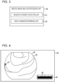
- the medical image analysis processing unit 36 performs analysis processing by using the medical images acquired by the medical image acquiring unit 11. As illustrated in Fig. 3 , the medical image analysis processing unit 36 includes a region-of-interest detecting unit 41 and a display-manner determining unit 42.
- the region-of-interest detecting unit 41 performs region-of-interest detection processing for detecting a region of interest 47 (see Fig. 4 to Fig. 6 , Fig. 16 , Fig. 17 , and Fig. 20 ) from the medical images.
- a neural network (NN), a convolutional neural network (CNN), AdaBoost, a random forest, or the like may be employed.
- the region of interest 47 may be detected on the basis of a feature quantity obtained as color information of a medical image, a gradient of a pixel value, or the like.
- the gradient of the pixel value or the like changes depending on, for example, the shape of the photographic subject (e.g., global ups and downs or local depression or projection in a mucous membrane), color (color of, for example, inflammation, bleeding, redness, or whitening due to atrophy), feature of an organ (e.g., blood vessel thickness, depth, density, or a combination thereof), feature of a structure (e.g., pit pattern), or the like.
- the region of interest 47 detected by the region-of-interest detecting unit 41 is a region including, for example, a lesion part typified by a cancer, a benign tumor part, an inflammation part (including, not only a so-called inflammation, but also a part with a change such as bleeding or atrophy), a marking part marked by cauterization by heating or colored with a colorant, a fluorescent agent, or the like, and a biopsy performing part where a biopsy is performed.
- the region of interest 47 may be a region including a lesion, a region that may possibly be a lesion, a region subjected to certain treatment including a biopsy, a treatment tool including a clip or forceps, a region that needs close observation, regardless of the possibility of a lesion, such as a dark region (a region behind a fold or depth of a luminal organ where observation light is difficult to be delivered), or the like.
- the region-of-interest detecting unit 41 detects, as the region of interest 47, a region including at least any of the lesion part, the benign tumor part, the inflammation part, the marking part, or the biopsy performing part.
- the display-manner determining unit 42 determines a display manner of report information for reporting that the region of interest 47 has been detected, and also determines a display manner of a medical image 43 (see Fig. 4 to Fig. 17 ). In accordance with the determined display manners, the display control unit 37 causes the display unit 34 to display the report information and the medical image 43.
- a first region 45 for displaying the medical image 43 and a second region 46 for displaying the report information are provided, and the display-manner determining unit 42 determines the display manners of images to be displayed in these first and second regions 45 and 46.
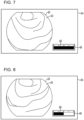
- Fig. 4 to Fig. 9 illustrate display screens 44 displaying, in screens (in the first region 45), a series of medical images 43 that are sequentially acquired in the order from Fig. 4 to Fig. 9 , along with an endoscope examination.
- Each of Fig. 4 , Fig. 5, and Fig. 6 illustrates a detected state in which the region of interest 47 is detected, whereas each of Fig. 7, Fig. 8 , and Fig. 9 illustrates an undetected state in which the region of interest 47 is not detected.
- the region of interest 47 is displayed to be superposed on the medical image 43 (see Fig. 4 , Fig. 5, and Fig. 6 ).
- the first region 45 in the undetected state only the medical image 43 is displayed (see Fig. 7, Fig. 8 , and Fig. 9 ).
- the region of interest 47 is displayed to be superposed on the medical image 43 by being hatched (see Fig. 4 , Fig. 5, and Fig. 6 ) in this embodiment.
- the region of interest 47 may also be displayed to be superposed on the medical image 43 by being colored.
- the region of interest 47 may also be displayed to be superposed on the medical image 43 by only the outline thereof being colored for emphasis. In this manner, the display form when displaying the region of interest 47 to be superposed on the medical image 43 can be changed as appropriate.
- the region of interest 47 may be emphasized by, for example, being surrounded by a frame.
- the configuration regarding the first region 45 may be such that only the medical image 43 is displayed without displaying or emphasizing the region of interest 47 even in the detected state.
- the configuration may be such that the state in which the region of interest 47 is displayed or emphasized and the state in which only the medical image 43 is displayed without displaying the region of interest 47 is switched by a selecting operation of a user (e.g., a physician performing an endoscopic examination).
- report information indicating that the region of interest 47 is present in the medical image 43 is displayed (see Fig. 4 , Fig. 5, and Fig. 6 ).
- the report information is displayed in the form of a bar 48 (time bar). Display of the bar 48 starts in a longest state when the undetected state transitions to the detected state, and display in the longest state is maintained until the detected state transitions to the undetected state. When the detected state transitions to the undetected state, the bar 48 is reduced in length over time (see Fig. 7, Fig. 8 , and Fig. 9 ).
- the bar 48 that is reduced in length over time is displayed in the second region 46. Note that when a predetermined time elapses after transition to the undetected state, the length of the bar 48 becomes 0, and the bar 48 disappears (becomes no longer displayed, see Fig. 9 ). In addition, in a case where the undetected state transitions to the detected state before the bar 48 disappears, the length of the bar 48 returns to the longest (see Fig. 4 , Fig. 5, and Fig. 6 ).
- the user can know whether the detection state is the detected state or the elapsed time after entering the undetected state.
- the region of interest 47 that has become out of the screen is to be returned to the inside of the screen again, it is likely to be intuitively understood how much the endoscope is to be moved back, and the region of interest 47 can be returned to the inside of the screen with ease, reducing the examination load.
- the present invention is not limited to the above embodiment, and detailed configurations can be changed as appropriate.
- the above embodiment has described an example of indicating the elapsed time by using a linear bar
- the elapsed time may alternatively be indicated by using a circular bar 49 as illustrated in Fig. 10 .
- the elapsed time may alternatively be indicated by changing color (display color) as illustrated in Fig. 11 and Fig. 12 .
- regions 50 and 51 colored in different colors are provided in the second region 46.
- the entirety of the second region 46 is the region 50.
- the region 50 is reduced over time (the length of the region 50 is made shorter in Fig. 11 , and the diameter of the region 50 is made smaller in Fig. 12 ), and, in contrast, the region 51 is increased to indicate the elapsed time.
- the elapsed time may also be indicated by changing the density of color (display color) and/or lightness thereof.
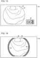
- the elapsed time may also be indicated by using a numeral.
- counting down is performed in the second region 46 (the numeric value in the second region 46 is decremented by one per second) to indicate the elapsed time.
- the elapsed time may also be indicated by using a character.
- the elapsed time may also be indicated by combining a plurality of methods described above, such as indicating the elapsed time by using both the bar and the numeric value.
- the elapsed time may also be indicated by increasing the bar and/or the numeric value or the like.
- the second region 46 may also be provided on a peripheral part of the first region 45.
- the peripheral part of the first region 45 may be a region inside the first region 45.
- the second region 46 is inside the first region 45 and in outer edge parts of the first region 45 (the regions illustrated by hatching in Fig. 14 ).
- the peripheral part of the first region 45 may also be a region outside the first region 45.
- the second region 46 is a rectangular frame-like region (the region illustrated by hatching in Fig. 15 ) provided outside the first region 45 so as to surround the first region 45.
- the peripheral part of the first region 45 may also be a region across both the region inside the first region 45 and the region outside the first region 45.
- the above embodiment has described an example of reporting, by details displayed in the second region 46, that the region of interest 47 has been detected and reporting the elapsed time after the region of interest 47 has no longer been detected.
- the present invention is not limited to this.
- the detected location of the region of interest 47 may also be reported.
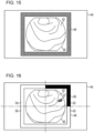
- the second region 46 is provided on the peripheral part of the first region 45, and the detected location of the region of interest 47 is reported by displaying a bar 56 in one of four regions 52 to 55 that are formed by dividing the second region 46 into four regions by using line segments passing through the center of the first region 45.
- the region of interest 47 has been detected in a case where the region of interest 47 has been detected in the upper right region on the screen.
- the bar 56 is displayed in the longest state in the upper right region 52 in the second region 46 on the screen; in a case where the region of interest 47 has been detected in the lower right region on the screen, the bar 56 is displayed in the longest state in the lower right region 53 in the second region 46 on the screen; in a case where the region of interest 47 has been detected in the upper left region on the screen, the bar 56 is displayed in the longest state in the upper left region 54 in the second region 46 on the screen; and in a case where the region of interest 47 has been detected in the lower left region on the screen, the bar 56 is displayed in the longest state in the lower left region 55 in the second region 46 on the screen.
- Fig. 16 and Fig. 20 illustrate the state in which the region of interest 47 has been detected in the upper right region 52 on the screen and the bar 56 is displayed in the region 52.
- the display position (the displayed region) of the bar 56 is moved corresponding to change of the location of the region of interest 47. If the detected state transitions to the undetected state, the display position of the bar 56 is not changed (i.e., the bar 56 is displayed at the position (in the region) corresponding to the most recent detected location of the region of interest 47), and the length of the bar 56 is reduced over time (e.g., the bar 56 is reduced from both ends so that the bar 56 remains in a corner portion of the second region 46).
- the location of the region of interest 47 is known with ease in the detected state.
- the detected location of the region of interest 47 at the last detection is known even in the undetected state. This makes it easier to return the region of interest 47 to the inside of the screen, further reducing the examination load.
- the display manner of the second region 46 for reporting the detected location of the region of interest 47 is not limited to this.
- examples of changing the display position of the bar 56 within the second region 46 depending on the location of the region of interest 47 has been described.
- the display position and/or the shape of the second region 46 itself may also be changed depending on the location of the region of interest 47.
- information about the region of interest 47 may also be displayed for a region in the second region 46, the region being different from the detected location of the region of interest 47.
- Fig. 17 information about the region of interest 47 may also be displayed for a region in the second region 46, the region being different from the detected location of the region of interest 47.
- the region 52 corresponding to the detected location of the region of interest 47 is colored in blue
- the region 55 that is the most distant from the detected location of the region of interest 47 is colored in red
- the regions 53 and 54 adjacent to the region corresponding to the detected location of the region of interest 47 are colored in yellow.
- the above embodiment has described an example of reporting both that the region of interest 47 has been detected and the elapsed time after the region of interest 47 has no longer been detected.
- the configuration may be such as to report only the elapsed time after the region of interest 47 has no longer been detected.
- the elapsed time after entering the undetected state may be reported by displaying, for example, the bar 48 described in the above embodiment when the detected state transitions to the undetected state, without display in the second region 46 (see Fig. 7 to Fig. 9 ).
- the medical image processing apparatus 10 may be included in a diagnosis support apparatus 610 using the endoscope apparatus 21 or other modalities and the PACS 22 in combination.
- the medical image processing apparatus 10 according to the above embodiment or other modifications may be included in a medical service support apparatus 630 that establishes connection with various examination apparatuses via any network 626.
- the various examination apparatuses are, for example, a first examination apparatus 621, a second examination apparatus 622, ..., an N-th examination apparatus 623, and the like, each including the endoscope apparatus 21.
- the medical image processing apparatus 10, the endoscope apparatus 21, and various apparatuses or systems including the medical image processing apparatus 10 can be used by making the following various changes, for example.
- an ordinary-light image may be used as the medical image.
- the ordinary-light image is obtained by radiating light of a white range or light of a plurality of wavelength ranges as the light of the white range.
- a range narrower than the white wavelength range may be used.
- the particular wavelength range is, for example, a visible wavelength range of blue or green.
- the particular wavelength range is the visible wavelength range of blue or green
- the particular wavelength range preferably includes a wavelength range that is greater than or equal to 390 nm and is less than or equal to 450 nm, or is greater than or equal to 530 nm and is less than or equal to 550 nm
- the light of the particular wavelength range preferably has a peak wavelength in the wavelength range that is greater than or equal to 390 nm and is less than or equal to 450 nm, or is greater than or equal to 530 nm and is less than or equal to 550 nm.
- the particular wavelength range is, for example, a visible wavelength range of red.
- the particular wavelength range preferably includes a wavelength range that is greater than or equal to 585 nm and is less than or equal to 615 nm, or is greater than or equal to 610 nm and is less than or equal to 730 nm, and the light of the particular wavelength range preferably has a peak wavelength in the wavelength range that is greater than or equal to 585 nm and is less than or equal to 615 nm, or is greater than or equal to 610 nm and is less than or equal to 730 nm.
- the particular wavelength range may include, for example, a wavelength range in which a light absorption coefficient differs between oxyhemoglobin and deoxyhemoglobin, and the light of the particular wavelength range may have a peak wavelength in the wavelength range in which the light absorption coefficient differs between oxyhemoglobin and deoxyhemoglobin.
- the particular wavelength range includes the wavelength range in which the light absorption coefficient differs between oxyhemoglobin and deoxyhemoglobin, and the light of the particular wavelength range has the peak wavelength in the wavelength range in which the light absorption coefficient differs between oxyhemoglobin and deoxyhemoglobin
- the particular wavelength range preferably includes a wavelength range of 400 ⁇ 10 nm, 440 ⁇ 10 nm, or 470 ⁇ 10 nm, or a wavelength range that is greater than or equal to 600 nm and is less than or equal to 750 nm
- the light of the particular wavelength range preferably has a peak wavelength in the wavelength range of 400 ⁇ 10 nm, 440 ⁇ 10 nm, or 470 ⁇ 10 nm, or in the wavelength range that is greater than or equal to 600 nm and is less than or equal to 750 nm.
- the medical image is an inside body image of an inside of a body
- the inside body image may have information of fluorescent light emitted by a fluorescence substance in the body.
- fluorescent light fluorescent light obtained by irradiating the inside of the body with excitation light having a peak wavelength that is greater than or equal to 390 nm and is less than or equal to 470 nm may be used.
- the medical image is an inside body image of an inside of a body
- a wavelength range of infrared light may be used.
- the particular wavelength range preferably includes a wavelength range that is greater than or equal to 790 nm and is less than or equal to 820 nm, or is greater than or equal to 905 nm and is less than or equal to 970 nm, and the light of the particular wavelength range preferably has a peak wavelength in the wavelength range that is greater than or equal to 790 nm and is less than or equal to 820 nm, or is greater than or equal to 905 nm and is less than or equal to 970 nm.
- the medical image acquiring unit 11 may include a special-light-image acquiring unit that acquires a special-light image having a signal in a particular wavelength range on the basis of the ordinary-light image obtained by radiating the light of the white range or by radiating light of a plurality of wavelength ranges as the light of the white range.
- the special-light image may be used as the medical image.
- the signal in the particular wavelength range may be obtained through a calculation based on color information of RGB or CMY included in the ordinary-light image.
- a feature-quantity-image generation unit may be included.
- the feature-quantity-image generation unit generates a feature-quantity image through a calculation based on at least one of the ordinary-light image that is obtained by radiating the light of the white range or light of a plurality of wavelength ranges as the light of the white range or the special-light image obtained by radiating the light of the particular wavelength range.
- the feature-quantity image may be used as the medical image.
- a capsule endoscope may be used as the endoscope 31.
- the light source device 32 and part of the processor device 33 may be installed on the capsule endoscope.
- a hardware structure of processing units that perform various kinds of processing such as the medical image acquiring unit 11, the medical image analysis processing unit 12, each unit constituting the medical image analysis processing unit 12, the display control unit 15, the input receiving unit 16, the general control unit 17, the medical image acquiring unit 35, the medical image analysis processing unit 36, the display control unit 37, the region-of-interest detecting unit 41, and the display-manner determining unit 42 is any of the following various processors.
- processors include a central processing unit (CPU) and a graphical processing unit (GPU) that are general-purpose processors functioning as various processing units by executing software (programs), a programmable logic device (PLD) that is a processor in which the circuit configuration is changeable after manufacture, such as field programmable gate array (FPGA), a dedicated electric circuit that is a processor having a circuit configuration that is specially designed to execute various kinds of processing, and the like.
- CPU central processing unit
- GPU graphical processing unit
- PLD programmable logic device
- FPGA field programmable gate array
- FPGA field programmable gate array
- One processing unit may be constituted by one of these various processors, or may be constituted by two or more processors of the same type or different types in combination (e.g., a combination of a plurality of FPGAs, a combination of a CPU and an FPGA, or a combination of a CPU and a GPU).
- a plurality of processing units may be constituted by one processor.
- one processor may be constituted by a combination of one or more CPUs and software, and this processor may function as a plurality of processing units, as typified by a computer such as a client or a server.
- a processor may be used that implements the functions of the entire system including a plurality of processing units with one integrated circuit (IC) chip, as typified by a system on chip (SoC) or the like.
- IC integrated circuit
- SoC system on chip
- various processing units are constituted by one or more of the above various processors in terms of hardware structure.
- the hardware structure of these various processors is electric circuitry constituted by combining circuit elements such as semiconductor elements.
Landscapes
- Engineering & Computer Science (AREA)
- Health & Medical Sciences (AREA)
- Life Sciences & Earth Sciences (AREA)
- Physics & Mathematics (AREA)
- General Health & Medical Sciences (AREA)
- Medical Informatics (AREA)
- Radiology & Medical Imaging (AREA)
- Nuclear Medicine, Radiotherapy & Molecular Imaging (AREA)
- Surgery (AREA)
- Public Health (AREA)
- Theoretical Computer Science (AREA)
- General Physics & Mathematics (AREA)
- Animal Behavior & Ethology (AREA)
- Pathology (AREA)
- Biomedical Technology (AREA)
- Heart & Thoracic Surgery (AREA)
- Molecular Biology (AREA)
- Biophysics (AREA)
- Optics & Photonics (AREA)
- Veterinary Medicine (AREA)
- Computer Hardware Design (AREA)
- Epidemiology (AREA)
- Primary Health Care (AREA)
- Quality & Reliability (AREA)
- Computer Vision & Pattern Recognition (AREA)
- Multimedia (AREA)
- Signal Processing (AREA)
- Endoscopes (AREA)
- Measuring And Recording Apparatus For Diagnosis (AREA)
Applications Claiming Priority (3)
| Application Number | Priority Date | Filing Date | Title |
|---|---|---|---|
| JP2018140953 | 2018-07-27 | ||
| EP19842298.2A EP3831272B1 (de) | 2018-07-27 | 2019-06-03 | Vorrichtung zur verarbeitung medizinischer bilder |
| PCT/JP2019/022047 WO2020021864A1 (ja) | 2018-07-27 | 2019-06-03 | 医療画像処理装置 |
Related Parent Applications (2)
| Application Number | Title | Priority Date | Filing Date |
|---|---|---|---|
| EP19842298.2A Division EP3831272B1 (de) | 2018-07-27 | 2019-06-03 | Vorrichtung zur verarbeitung medizinischer bilder |
| EP19842298.2A Division-Into EP3831272B1 (de) | 2018-07-27 | 2019-06-03 | Vorrichtung zur verarbeitung medizinischer bilder |
Publications (3)
| Publication Number | Publication Date |
|---|---|
| EP4339900A2 true EP4339900A2 (de) | 2024-03-20 |
| EP4339900A3 EP4339900A3 (de) | 2024-06-19 |
| EP4339900A8 EP4339900A8 (de) | 2026-01-07 |
Family
ID=69180889
Family Applications (2)
| Application Number | Title | Priority Date | Filing Date |
|---|---|---|---|
| EP24154246.3A Pending EP4339900A3 (de) | 2018-07-27 | 2019-06-03 | Medizinische bildverarbeitungsvorrichtung, endoskopsystem und verfahren zum betrieb einer medizinischen bildverarbeitungsvorrichtung |
| EP19842298.2A Active EP3831272B1 (de) | 2018-07-27 | 2019-06-03 | Vorrichtung zur verarbeitung medizinischer bilder |
Family Applications After (1)
| Application Number | Title | Priority Date | Filing Date |
|---|---|---|---|
| EP19842298.2A Active EP3831272B1 (de) | 2018-07-27 | 2019-06-03 | Vorrichtung zur verarbeitung medizinischer bilder |
Country Status (5)
| Country | Link |
|---|---|
| US (3) | US11605363B2 (de) |
| EP (2) | EP4339900A3 (de) |
| JP (1) | JP7125987B2 (de) |
| CN (1) | CN112512398B (de) |
| WO (1) | WO2020021864A1 (de) |
Families Citing this family (7)
| Publication number | Priority date | Publication date | Assignee | Title |
|---|---|---|---|---|
| CN112584739B (zh) * | 2018-08-20 | 2024-04-05 | 富士胶片株式会社 | 医疗图像处理系统 |
| JP7038641B2 (ja) * | 2018-11-02 | 2022-03-18 | 富士フイルム株式会社 | 医療診断支援装置、内視鏡システム、及び作動方法 |
| JP7286948B2 (ja) * | 2018-11-07 | 2023-06-06 | ソニーグループ株式会社 | 医療用観察システム、信号処理装置及び医療用観察方法 |
| WO2020136858A1 (ja) * | 2018-12-28 | 2020-07-02 | オリンパス株式会社 | 内視鏡画像処理装置、内視鏡画像処理方法及びプログラム |
| EP4100875A1 (de) * | 2020-02-03 | 2022-12-14 | Cosmo Artificial Intelligence - AI Limited | Systeme und verfahren zur kontextuellen bildanalyse |
| EP4129151A4 (de) * | 2020-03-31 | 2023-12-13 | NEC Corporation | Informationsverarbeitungsvorrichtung, anzeigeverfahren und nichttransitorisches computerlesbares medium mit darauf gespeichertem programm |
| JP2025026062A (ja) * | 2023-08-10 | 2025-02-21 | 富士フイルム株式会社 | 医療支援装置、内視鏡装置、医療支援方法、及びプログラム |
Citations (2)
| Publication number | Priority date | Publication date | Assignee | Title |
|---|---|---|---|---|
| JP2011160848A (ja) | 2010-02-05 | 2011-08-25 | Olympus Corp | 画像処理装置、内視鏡システム、プログラム及び画像処理方法 |
| US20110254937A1 (en) | 2010-04-15 | 2011-10-20 | Olympus Corporation | Image processing device and program |
Family Cites Families (11)
| Publication number | Priority date | Publication date | Assignee | Title |
|---|---|---|---|---|
| US8048069B2 (en) * | 2006-09-29 | 2011-11-01 | Medtronic, Inc. | User interface for ablation therapy |
| JP5374135B2 (ja) * | 2008-12-16 | 2013-12-25 | オリンパス株式会社 | 画像処理装置、画像処理装置の作動方法および画像処理プログラム |
| JP4923096B2 (ja) * | 2009-11-30 | 2012-04-25 | オリンパスメディカルシステムズ株式会社 | 画像表示装置 |
| JP5972561B2 (ja) | 2011-12-08 | 2016-08-17 | 東芝メディカルシステムズ株式会社 | 超音波診断装置、画像処理装置及び画像処理プログラム |
| JP2013135776A (ja) * | 2011-12-28 | 2013-07-11 | Toshiba Corp | 超音波診断装置 |
| US10242489B2 (en) | 2014-06-26 | 2019-03-26 | Hitachi, Ltd. | Image processing device, image processing method and image processing system |
| JP6734028B2 (ja) * | 2014-11-14 | 2020-08-05 | キヤノンメディカルシステムズ株式会社 | 医用画像診断装置、画像処理装置及び画像生成方法 |
| JP6418940B2 (ja) * | 2014-12-25 | 2018-11-07 | キヤノン株式会社 | 電子機器及びその制御方法 |
| EP3360461A4 (de) * | 2015-11-10 | 2019-05-08 | Olympus Corporation | Endoskopvorrichtung |
| WO2018216617A1 (ja) | 2017-05-25 | 2018-11-29 | 日本電気株式会社 | 情報処理装置、制御方法、及びプログラム |
| US20180358124A1 (en) * | 2017-06-09 | 2018-12-13 | Precision Dynamics Corporation | Healthcare Reminder Label System With Visual Indicator |
-
2019
- 2019-06-03 WO PCT/JP2019/022047 patent/WO2020021864A1/ja not_active Ceased
- 2019-06-03 CN CN201980050136.4A patent/CN112512398B/zh active Active
- 2019-06-03 EP EP24154246.3A patent/EP4339900A3/de active Pending
- 2019-06-03 JP JP2020532194A patent/JP7125987B2/ja active Active
- 2019-06-03 EP EP19842298.2A patent/EP3831272B1/de active Active
-
2020
- 2020-12-21 US US17/129,864 patent/US11605363B2/en active Active
-
2023
- 2023-01-09 US US18/151,473 patent/US11881190B2/en active Active
- 2023-11-29 US US18/523,831 patent/US12217726B2/en active Active
Patent Citations (2)
| Publication number | Priority date | Publication date | Assignee | Title |
|---|---|---|---|---|
| JP2011160848A (ja) | 2010-02-05 | 2011-08-25 | Olympus Corp | 画像処理装置、内視鏡システム、プログラム及び画像処理方法 |
| US20110254937A1 (en) | 2010-04-15 | 2011-10-20 | Olympus Corporation | Image processing device and program |
Also Published As
| Publication number | Publication date |
|---|---|
| US20240105143A1 (en) | 2024-03-28 |
| EP4339900A3 (de) | 2024-06-19 |
| CN112512398A (zh) | 2021-03-16 |
| JPWO2020021864A1 (ja) | 2021-07-01 |
| US11881190B2 (en) | 2024-01-23 |
| US20230162703A1 (en) | 2023-05-25 |
| JP7125987B2 (ja) | 2022-08-25 |
| EP3831272A4 (de) | 2021-11-17 |
| EP3831272B1 (de) | 2024-03-27 |
| EP3831272A1 (de) | 2021-06-09 |
| US20210110915A1 (en) | 2021-04-15 |
| US12217726B2 (en) | 2025-02-04 |
| WO2020021864A1 (ja) | 2020-01-30 |
| US11605363B2 (en) | 2023-03-14 |
| EP4339900A8 (de) | 2026-01-07 |
| CN112512398B (zh) | 2024-03-29 |
Similar Documents
| Publication | Publication Date | Title |
|---|---|---|
| US12217726B2 (en) | Medical image processing apparatus | |
| EP3841954B1 (de) | Medizinisches bildverarbeitungssystem | |
| EP3841953B1 (de) | Medizinisches bildverarbeitungssystem | |
| EP3449799A1 (de) | Vorrichtung zur verarbeitung medizinischer bilder, endoskopvorrichtung, diagnoseunterstützungsvorrichtung und vorrichtung zur unterstützung medizinischer dienste | |
| US11862327B2 (en) | Medical image processing system | |
| WO2019008941A1 (ja) | 医療画像処理装置、内視鏡装置、診断支援装置、医療業務支援装置、及び、レポート作成支援装置 | |
| US11950757B2 (en) | Medical image processing apparatus | |
| US20210161366A1 (en) | Endoscope system and medical image processing system | |
| EP4133991A1 (de) | System zur verarbeitung medizinischer bilder, prozessor zur verarbeitung von erkennungsdaten und betriebsverfahren für das system zur verarbeitung medizinischer bilder | |
| JP2020058623A (ja) | 医用画像処理装置、医用画像処理方法及び医用画像処理プログラム |
Legal Events
| Date | Code | Title | Description |
|---|---|---|---|
| PUAI | Public reference made under article 153(3) epc to a published international application that has entered the european phase |
Free format text: ORIGINAL CODE: 0009012 |
|
| STAA | Information on the status of an ep patent application or granted ep patent |
Free format text: STATUS: THE APPLICATION HAS BEEN PUBLISHED |
|
| AC | Divisional application: reference to earlier application |
Ref document number: 3831272 Country of ref document: EP Kind code of ref document: P |
|
| AK | Designated contracting states |
Kind code of ref document: A2 Designated state(s): AL AT BE BG CH CY CZ DE DK EE ES FI FR GB GR HR HU IE IS IT LI LT LU LV MC MK MT NL NO PL PT RO RS SE SI SK SM TR |
|
| PUAL | Search report despatched |
Free format text: ORIGINAL CODE: 0009013 |
|
| AK | Designated contracting states |
Kind code of ref document: A3 Designated state(s): AL AT BE BG CH CY CZ DE DK EE ES FI FR GB GR HR HU IE IS IT LI LT LU LV MC MK MT NL NO PL PT RO RS SE SI SK SM TR |
|
| RIC1 | Information provided on ipc code assigned before grant |
Ipc: G06T 7/00 20170101ALI20240514BHEP Ipc: G16H 30/40 20180101ALI20240514BHEP Ipc: G16H 30/20 20180101ALI20240514BHEP Ipc: G09G 5/14 20060101ALI20240514BHEP Ipc: G09G 5/02 20060101ALI20240514BHEP Ipc: A61B 1/045 20060101ALI20240514BHEP Ipc: A61B 1/00 20060101ALI20240514BHEP Ipc: G06V 10/25 20220101AFI20240514BHEP |
|
| STAA | Information on the status of an ep patent application or granted ep patent |
Free format text: STATUS: REQUEST FOR EXAMINATION WAS MADE |
|
| 17P | Request for examination filed |
Effective date: 20241202 |
|
| RBV | Designated contracting states (corrected) |
Designated state(s): AL AT BE BG CH CY CZ DE DK EE ES FI FR GB GR HR HU IE IS IT LI LT LU LV MC MK MT NL NO PL PT RO RS SE SI SK SM TR |
|
| RAP3 | Party data changed (applicant data changed or rights of an application transferred) |
Owner name: FUJIFILM CORPORATION |
|
| GRAP | Despatch of communication of intention to grant a patent |
Free format text: ORIGINAL CODE: EPIDOSNIGR1 |
|
| STAA | Information on the status of an ep patent application or granted ep patent |
Free format text: STATUS: GRANT OF PATENT IS INTENDED |
|
| INTG | Intention to grant announced |
Effective date: 20260317 |