EP4340108B1 - Appareil de contrainte et dispositif de contrainte - Google Patents
Appareil de contrainte et dispositif de contrainte Download PDFInfo
- Publication number
- EP4340108B1 EP4340108B1 EP23163892.5A EP23163892A EP4340108B1 EP 4340108 B1 EP4340108 B1 EP 4340108B1 EP 23163892 A EP23163892 A EP 23163892A EP 4340108 B1 EP4340108 B1 EP 4340108B1
- Authority
- EP
- European Patent Office
- Prior art keywords
- assembly
- positioning
- constraining
- state
- end plate
- Prior art date
- Legal status (The legal status is an assumption and is not a legal conclusion. Google has not performed a legal analysis and makes no representation as to the accuracy of the status listed.)
- Active
Links
Images



Classifications
-
- H—ELECTRICITY
- H01—ELECTRIC ELEMENTS
- H01M—PROCESSES OR MEANS, e.g. BATTERIES, FOR THE DIRECT CONVERSION OF CHEMICAL ENERGY INTO ELECTRICAL ENERGY
- H01M50/00—Constructional details or processes of manufacture of the non-active parts of electrochemical cells other than fuel cells, e.g. hybrid cells
- H01M50/20—Mountings; Secondary casings or frames; Racks, modules or packs; Suspension devices; Shock absorbers; Transport or carrying devices; Holders
- H01M50/204—Racks, modules or packs for multiple batteries or multiple cells
- H01M50/207—Racks, modules or packs for multiple batteries or multiple cells characterised by their shape
- H01M50/209—Racks, modules or packs for multiple batteries or multiple cells characterised by their shape adapted for prismatic or rectangular cells
-
- H—ELECTRICITY
- H01—ELECTRIC ELEMENTS
- H01M—PROCESSES OR MEANS, e.g. BATTERIES, FOR THE DIRECT CONVERSION OF CHEMICAL ENERGY INTO ELECTRICAL ENERGY
- H01M50/00—Constructional details or processes of manufacture of the non-active parts of electrochemical cells other than fuel cells, e.g. hybrid cells
- H01M50/20—Mountings; Secondary casings or frames; Racks, modules or packs; Suspension devices; Shock absorbers; Transport or carrying devices; Holders
- H01M50/262—Mountings; Secondary casings or frames; Racks, modules or packs; Suspension devices; Shock absorbers; Transport or carrying devices; Holders with fastening means, e.g. locks
- H01M50/264—Mountings; Secondary casings or frames; Racks, modules or packs; Suspension devices; Shock absorbers; Transport or carrying devices; Holders with fastening means, e.g. locks for cells or batteries, e.g. straps, tie rods or peripheral frames
-
- H—ELECTRICITY
- H01—ELECTRIC ELEMENTS
- H01M—PROCESSES OR MEANS, e.g. BATTERIES, FOR THE DIRECT CONVERSION OF CHEMICAL ENERGY INTO ELECTRICAL ENERGY
- H01M50/00—Constructional details or processes of manufacture of the non-active parts of electrochemical cells other than fuel cells, e.g. hybrid cells
- H01M50/20—Mountings; Secondary casings or frames; Racks, modules or packs; Suspension devices; Shock absorbers; Transport or carrying devices; Holders
- H01M50/289—Mountings; Secondary casings or frames; Racks, modules or packs; Suspension devices; Shock absorbers; Transport or carrying devices; Holders characterised by spacing elements or positioning means within frames, racks or packs
-
- H—ELECTRICITY
- H01—ELECTRIC ELEMENTS
- H01M—PROCESSES OR MEANS, e.g. BATTERIES, FOR THE DIRECT CONVERSION OF CHEMICAL ENERGY INTO ELECTRICAL ENERGY
- H01M50/00—Constructional details or processes of manufacture of the non-active parts of electrochemical cells other than fuel cells, e.g. hybrid cells
- H01M50/20—Mountings; Secondary casings or frames; Racks, modules or packs; Suspension devices; Shock absorbers; Transport or carrying devices; Holders
- H01M50/289—Mountings; Secondary casings or frames; Racks, modules or packs; Suspension devices; Shock absorbers; Transport or carrying devices; Holders characterised by spacing elements or positioning means within frames, racks or packs
- H01M50/291—Mountings; Secondary casings or frames; Racks, modules or packs; Suspension devices; Shock absorbers; Transport or carrying devices; Holders characterised by spacing elements or positioning means within frames, racks or packs characterised by their shape
-
- H—ELECTRICITY
- H01—ELECTRIC ELEMENTS
- H01M—PROCESSES OR MEANS, e.g. BATTERIES, FOR THE DIRECT CONVERSION OF CHEMICAL ENERGY INTO ELECTRICAL ENERGY
- H01M10/00—Secondary cells; Manufacture thereof
- H01M10/04—Construction or manufacture in general
- H01M10/0481—Compression means other than compression means for stacks of electrodes and separators
-
- H—ELECTRICITY
- H01—ELECTRIC ELEMENTS
- H01M—PROCESSES OR MEANS, e.g. BATTERIES, FOR THE DIRECT CONVERSION OF CHEMICAL ENERGY INTO ELECTRICAL ENERGY
- H01M50/00—Constructional details or processes of manufacture of the non-active parts of electrochemical cells other than fuel cells, e.g. hybrid cells
- H01M50/20—Mountings; Secondary casings or frames; Racks, modules or packs; Suspension devices; Shock absorbers; Transport or carrying devices; Holders
- H01M50/289—Mountings; Secondary casings or frames; Racks, modules or packs; Suspension devices; Shock absorbers; Transport or carrying devices; Holders characterised by spacing elements or positioning means within frames, racks or packs
- H01M50/293—Mountings; Secondary casings or frames; Racks, modules or packs; Suspension devices; Shock absorbers; Transport or carrying devices; Holders characterised by spacing elements or positioning means within frames, racks or packs characterised by the material
-
- Y—GENERAL TAGGING OF NEW TECHNOLOGICAL DEVELOPMENTS; GENERAL TAGGING OF CROSS-SECTIONAL TECHNOLOGIES SPANNING OVER SEVERAL SECTIONS OF THE IPC; TECHNICAL SUBJECTS COVERED BY FORMER USPC CROSS-REFERENCE ART COLLECTIONS [XRACs] AND DIGESTS
- Y02—TECHNOLOGIES OR APPLICATIONS FOR MITIGATION OR ADAPTATION AGAINST CLIMATE CHANGE
- Y02E—REDUCTION OF GREENHOUSE GAS [GHG] EMISSIONS, RELATED TO ENERGY GENERATION, TRANSMISSION OR DISTRIBUTION
- Y02E60/00—Enabling technologies; Technologies with a potential or indirect contribution to GHG emissions mitigation
- Y02E60/10—Energy storage using batteries
-
- Y—GENERAL TAGGING OF NEW TECHNOLOGICAL DEVELOPMENTS; GENERAL TAGGING OF CROSS-SECTIONAL TECHNOLOGIES SPANNING OVER SEVERAL SECTIONS OF THE IPC; TECHNICAL SUBJECTS COVERED BY FORMER USPC CROSS-REFERENCE ART COLLECTIONS [XRACs] AND DIGESTS
- Y02—TECHNOLOGIES OR APPLICATIONS FOR MITIGATION OR ADAPTATION AGAINST CLIMATE CHANGE
- Y02P—CLIMATE CHANGE MITIGATION TECHNOLOGIES IN THE PRODUCTION OR PROCESSING OF GOODS
- Y02P70/00—Climate change mitigation technologies in the production process for final industrial or consumer products
- Y02P70/50—Manufacturing or production processes characterised by the final manufactured product
Definitions
- This application relates to the field of battery technologies, and in particular, to a constraining apparatus and a constraining device that are applied to battery cells.
- Both formation and grading processes for battery cell production relate to charging and discharging of battery cells. In these two processes, excess gas is easily generated inside battery cells. If the gas is not fully discharged, the defect rate of battery cells will increase. To alleviate this problem, battery cells need to be constrained to promote discharge of gas inside the battery cells.
- constraining trays are generally used to constrain battery cells.
- the constraining effect of existing constraining trays is unsatisfying, so the gas inside the battery cells cannot be fully discharged, thus failing to significantly alleviate the defect rate of battery cells. Therefore, it is urgent to develop a constraining apparatus, which provides good constraining effects for a lower defect rate of battery cells.
- US 2018/138560 A2 discloses a power supply device that enables insulation of surfaces of battery cells at low cost as well as simplifies an insulating structure between battery cells while maintaining an insulated state between battery cells and a fastening member to effectively prevent a short circuit caused by condensed water or the like.
- DE 10 2013 020 860 A1 relates to a cell block for a battery, comprising a number of individual cells which are electrically connected to one another in series and/or in parallel and are fixed within the cell block by means of mechanical fixing elements, and tensioning means for tensioning the fixed individual cells, wherein the cell block comprises an elasticity which can be predetermined in longitudinal expansion.
- US 10 388 934 B2 relates to a battery module including an array body with a plurality of battery cells held by cell holders and arranged along a predetermined array direction, and elastic members disposed between adjacent battery cells, and a restraint member applying a restraining load to the array body in the array direction, wherein the cell holder has a protrusion protruding in the array direction, and wherein a compression amount of the elastic member between the battery cells is regulated by the protrusion abutting on a cell holder of an adjacent battery cell.
- EP 3 121 868 A1 relates to a pressurization device for pressurizing flatshaped battery cells in the thickness direction of the battery cells.
- this application provides a constraining apparatus, applied to constrain a battery cell.
- the constraining apparatus includes a base, a positioning assembly, and a cushion assembly.
- the base includes a support assembly, a guide assembly, and two end plate assemblies, where the two end plate assemblies are respectively connected to two ends of the support assembly that are opposite each other in a first direction.
- the guide assembly extends in the first direction and is connected to the two end plate assemblies.
- the positioning assembly includes a plurality of positioning members arranged in sequence in the first direction and located between two end plate assemblies, where the plurality of positioning members are movably connected to the guide assembly in the first direction, and adjacent two of the positioning members are fitted to each other in the first direction.
- the cushion assembly is disposed on at least one of two sides of the positioning member that are opposite each other in the first direction.
- the constraining apparatus includes a first state and a second state, where in the first state, adjacent two of the positioning members abut against each other, such that an accommodating space for accommodating a battery cell is formed between the adjacent two of the positioning members, and the cushion assembly is configured to abut against the battery cell and the positioning members; and in the second state, the plurality of positioning members are spaced apart from each other in the first direction.
- the first state and the second state is freely switched by moving the positioning members.
- the constraining apparatus includes the first state and the second state.
- the first state is a state of exerting constraint on the battery cell
- the second state is a state of releasing constraint on the battery cell.
- the constraining apparatus can freely switch between the first state and the second state by moving the positioning member.
- the cushion assembly Under the condition that the constraining apparatus is in the first state, the cushion assembly abuts against the battery cell and the positioning members, and the cushion assembly has an elastic force, which can be converted into a constraining force on the battery cell.
- the battery cell is always subject to the constraining force applied by the cushion assembly in a gas discharging process, and the gas inside the battery cell can be fully discharged. This greatly improves the constraining effect of the constraining apparatus and decreases a defect rate of battery cells.
- gaps are present between the plurality of positioning members, facilitating loading and unloading of the battery cells.
- the positioning assembly is provided in plurality, where the plurality of positioning assemblies are disposed successively in a second direction, and the second direction is perpendicular to the first direction.
- Such arrangement of the plurality of positioning assemblies can increase a quantity of the battery cells constrained by the constraining apparatus in one constraint, improving the constraining efficiency of the constraining apparatus.
- the positioning member includes two positioning pieces and a restricting piece.
- the two positioning pieces are disposed opposite each other in the second direction, and are movably connected to the guide assembly in the first direction.
- the second direction is perpendicular to the first direction.
- the restricting piece is detachably connected between the two positioning pieces, and the cushion assembly is disposed on the restricting piece.
- An accommodating space is formed between the restricting pieces of adjacent two of the positioning members, and the cushion assembly is configured to be disposed between the restricting pieces and the battery cells.
- the positioning pieces and the restricting piece in the positioning member are detachably connected, such that the positioning assembly can be replaced to adapt to different types of battery cells. This improves versatility and convenience of use of the constraining apparatus.
- the restricting piece includes a body and two first convex portions connected to the body, where the two first convex portions respectively protrude in a direction towards the positioning pieces with respect to the body, and the body is connected to the cushion assembly.
- the positioning piece includes a main body and first concave portions, where the first concave portions is depressed in a direction away from the restricting pieces with respect to the main body, and the first concave portions are fitted to the first convex portions.
- a detachable connection between the restricting piece and the positioning pieces is implemented through such a form of fitting between the first convex portion and the first concave portion.
- This connection form contributes to a simple structure, good connection stability, and good reliability.
- the positioning piece includes a main body, a second convex portion, and a second concave portion, where the second convex portion is connected to the main body and protrudes in the first direction with respect to the main body.
- the second concave portion is connected to the main body, depressed in the first direction with respect to the main body, and disposed opposite the second convex portion in the first direction. In the first direction, the second convex portion of one of the two adjacent positioning pieces is fitted to the second concave portion of the other one of the two adjacent positioning pieces.
- the fitting is implemented between the two adjacent positioning pieces by using the second convex portion and the second concave portion. Under the condition that the constraining apparatus is in the first state, the structural stability between the two adjacent positioning pieces can be enhanced when the two abut against each other, thereby enhancing the structural stability of the constraining apparatus during operation.
- the restricting piece includes a body and a third convex portion connected to the body, where the third convex portion protrudes in the first direction with respect to the body and encloses a first cavity, the accommodating space is formed between the first cavities of adjacent two of the positioning members, and the cushion assembly is disposed in the first cavity.
- the third convex portion can restrict and position the battery cell to some extent, enhancing the positional stability of the battery cell when the battery cell is constrained, and thereby enhancing the overall structural stability of the constraining apparatus.
- the cushion assembly is disposed in the first cavity, which can also enhance the connection stability of the cushion assembly.
- a plurality of through holes are provided on the body.
- a plurality of protrusions are provided on a side of the cushion assembly facing the body and embedded in the through holes.
- the through holes are matched with the protrusions, such that the cushion assembly can be detachably connected to the body, thereby facilitating the disassembly and replacement of the cushion assembly. Moreover, such a connection form, in which the protrusions match the through holes, simplifies the structure, improves stability, and reduces manufacturing costs.
- the guide assembly includes a plurality of guide shafts extending in the first direction, where the plurality of guide shafts are spaced apart from each other in a direction perpendicular to the first direction.
- the positioning member includes a plurality of movable portions, where each of the movable portions is movably connected to its corresponding guide shaft.
- the guide assembly includes a plurality of guide shafts, which can enhance the stationarity of the positioning member moving along the guide assembly and enhance the operating stability of the constraining apparatus.
- the guide shafts feature simple structure, ease of manufacturing and molding, and low cost.
- the constraining apparatus further includes a holding assembly and a jacking assembly.
- the holding assembly is disposed on a side of the end plate assembly close to the positioning member; and the jacking assembly is disposed on the end plate assembly and can move in the first direction with respect to the end plate assembly.
- the jacking assembly In the first state, the jacking assembly is locked with the end plate assembly, and the holding assembly abuts against the jacking assembly and the positioning member; and in the second state, the jacking assembly is locked with the end plate assembly, and the jacking assembly is disengaged from the holding assembly.
- the jacking assembly can fit with the holding assembly, enabling the constraining apparatus to switch between the first state and the second state. This can simplify the operation of the constraining apparatus and improve the operation convenience of the constraining apparatus.
- the holding assembly is movably connected to the guide assembly in the first direction.
- the holding assembly is movably connected to the guide assembly, which enhances the movement stationarity of the holding assembly, thereby enhancing the overall structural stability of the constraining apparatus.
- the holding assembly in the second state, is fitted to the end plate assembly.
- the holding assembly can be fitted to the end plate assembly, such that the holding assembly and the base can be incorporated as a whole, enhancing the structural integrity of the constraining apparatus.
- the end plate assembly includes a plurality of mounting portions, where the plurality of mounting portions are spaced apart from each other, and the jacking assembly is disposed on the mounting portion.
- the end plate assembly includes the plurality of mounting portions, and can change a position of the jacking assembly according to the sizes of battery cells, such that the pressure applied by the jacking assembly can be more evenly distributed on the battery cells.
- a plurality of jacking assemblies may also be provided to pressurize the holding assembly so as to improve effect of constraining the battery cells.
- the holding assembly includes a plurality of matching portions disposed opposite the mounting portion in the first direction. In the first state, the jacking assembly abuts against the matching portions; and in the second state, the jacking assembly is disengaged from the matching portions.
- the matching portions are fitted to the jacking assembly, which can improve the abutment stability when the jacking assembly abuts against the holding assembly, and improve the overall structural stability of the constraining apparatus.
- this application provides a constraining device, including the constraining apparatus according to any one of the implementations of the first aspect and a pressurizing apparatus.
- the pressurizing apparatus is configured to exert an acting force on the positioning assembly in a first sub-direction, such that the constraining apparatus is in the first state and adjacent two of the positioning members abut against each other, and the first sub-direction is parallel to the first direction.
- the constraining device includes the pressurizing apparatus such that human intervention can be reduced in constraining the battery cells. This raises the automation level of the constraining device and improves the constraining efficiency.
- the constraining device further includes a pressure relief apparatus, where the pressure relief apparatus is configured to exert an acting force on the positioning assembly in a direction opposite the first sub-direction, such that the constraining apparatus is in the second state and the positioning members are spaced apart from each other in the first direction.
- the constraining device includes the pressure relief apparatus such that human intervention can be reduced in constraining the battery cells. This raises the automation level of the constraining device and improves the constraining efficiency.
- the constraining apparatus further includes the holding assembly and the jacking assembly; and the constraining device further includes a screw tightening apparatus.
- the screw tightening apparatus is configured to connect to the jacking assembly, so as to drive the jacking assembly to rotate and push the holding assembly to move in the first sub-direction.
- the screw tightening apparatus can press against the holding assembly, so as to maintain the compaction action on the positioning assembly and keep the constraining apparatus in the first state.
- the terms “mount”, “connect”, “join”, and “attach” should be understood in their general senses. For example, they may refer to a fixed connection, a detachable connection, or an integral connection, and may refer to a direct connection, an indirect connection via an intermediate medium, or an internal communication between two elements. A person of ordinary skills in the art can understand specific meanings of these terms in this application as appropriate to specific situations.
- a plurality of means more than two (inclusive).
- the battery cell may include a lithium-ion secondary battery, a lithium-ion primary battery, a lithium-sulfur battery, a sodium-lithium-ion battery, a sodium-ion battery, a magnesium-ion battery, or the like. This is not limited in the embodiments of this application.
- Processes such as formation and grading are generally required for production of battery cells.
- Battery cells are not energized when assembled. Therefore, the battery cells usually need to be charged for the first time to activate the active material inside the battery cells, and the process of first charge activation is called formation.
- Grading refers to a procedure of selecting qualified battery cells through capacity testing. During grading, battery cells are charged and discharged to detect discharge capacities of fully charged battery cells, so as to determine capacities of the battery cells. Only when the tested capacities reach or exceed the designed capacity, the battery cells are qualified. In the processes of formation and grading, a large amount of gas is easily generated in the battery cell. If the gas is not fully discharged, the internal air pressure of the battery cell will increase, and the battery cell will swell. As a result, the performance of battery cells does not meet the design requirements, thereby increasing the defect rate of battery cells.
- a constraining apparatus is generally configured to exert constraint on battery cells, so as to promote discharge of gas in the battery cells.
- the inventors have found through research that the existing constraining apparatuses have an unsatisfying effect in constraining the battery cells, and the gas in the battery cells is often unable to be fully discharged. Therefore, the problem of limited gas discharge cannot be alleviated significantly and the defect rate of battery cells cannot be decreased.
- the constraining apparatus includes a plurality of cushion assemblies and a plurality of positioning members.
- the plurality of positioning members are movable, and an accommodating space is provided between adjacent positioning members for accommodating a battery cell.
- the cushion assembly abuts against the battery cell and the positioning members.
- the constraining apparatus includes a first state and a second state.
- the first state is a state of exerting constraint on the battery cell
- the second state is a state of releasing constraint on the battery cell.
- the constraining apparatus can freely switch between the first state and the second state by moving the positioning members.
- the cushion assembly Under the condition that the constraining apparatus is in the first state, the cushion assembly abuts against the battery cell and the positioning members, and the cushion assembly has an elastic force, which is converted into a constraining force on the battery cell In this case, the battery cell is always subject to the constraining force applied by the cushion assembly in a gas discharging process, and the gas inside the battery cell can be fully discharged. This greatly improves the constraining effect of the constraining apparatus and decreases a defect rate of battery cells. Under the condition that the constraining apparatus is in the second state, gaps are present between the plurality of positioning members, facilitating loading and unloading of the battery cells.
- FIG. 1 is a schematic structural diagram of a constraining apparatus according to some embodiments of this application; and FIG. 2 is a partially exploded schematic diagram of a constraining apparatus according to some embodiments of this application.
- the constraining apparatus includes a base 1, a positioning assembly 2, and a cushion assembly 3.
- the base 1 includes a support assembly 11, a guide assembly 12, and two end plate assemblies 13, where the two end plate assemblies 13 are respectively connected to two ends of the support assembly 11 that are opposite each other in a first direction X.
- the guide assembly 12 extends in the first direction X and is connected to the two end plate assemblies 13.
- the positioning assembly 2 includes a plurality of positioning members 20 arranged in sequence in the first direction X and located between two end plate assemblies 13, where the plurality of positioning members 20 are movably connected to the guide assembly 12 in the first direction X, and adjacent two of the positioning members 20 are fitted to each other in the first direction X.
- the cushion assembly 3 is disposed on at least one of two sides of the positioning member 20 that are opposite each other in the first direction X.
- the constraining apparatus includes a first state and a second state, where in the first state, adjacent two of the positioning members 20 abut against each other, such that an accommodating space 4 for accommodating a battery cell 10 is formed between the adjacent two of the positioning members 20, and the cushion assembly 3 is configured to abut against the battery cell 10 and positioning members 20; and in the second state, the plurality of positioning members 20 are spaced apart from each other in the first direction X.
- the base 1 serves as the main body of the constraining apparatus, and can be provided in various structural forms, for example, a cuboid structure and a cube structure.
- the base 1 includes a support assembly 11, a guide assembly 12, and two end plate assemblies 13, where the support assembly 11 constitutes the supporting body of the constraining apparatus and has good structural strength and bearing capacity.
- the support assembly 11 may be made of metal materials, for example, alloy steel, or may be made of non-metal materials such as carbon fiber materials.
- the end plate assembly 13 is connected to two ends of the support assembly 11 that are opposite each other in the first direction X, and the end plate assembly 13 plays a minor role in supporting and is configured to support the positioning assembly 2 and withstand the pressure applied by the positioning assembly 2.
- the end plate assembly 13 may be connected to the support assembly 11 in various manners, which may be a fixed connection such as welding, or may be a detachable connection such as fitting and threaded connection.
- the support assembly 11 is formed by welding a plurality of steel pipes in an interlacing mode
- the end plate assembly 13 is a solid steel plate provided with a hollow groove and reinforcing ribs, and the two are welded together.
- the guide assembly 12 is connected between the two end plate assemblies 13.
- the guide assembly 12 can have various structural forms, for example, it may be a guide shaft or a guide rod; the guide assembly 12 and the end plate assembly 13 may be fixedly connected, for example, a welded connection, or may be detachably connected, for example, a fitting and threaded connection.
- the positioning assembly 2 is a main functional part of the constraining apparatus to exert constraint, and is configured to exert constraint on the battery cell 10.
- the positioning assembly 2 includes a plurality of positioning members 20.
- the plurality of positioning members 20 are arranged in sequence in the first direction X, and are movably connected to the guide assembly 12 in the first direction X.
- the movable connection in the first direction X means that the positioning members 20 are connected to the guide assembly 12, and can also move in the first direction X with respect to the guide assembly 12.
- an accommodating space 4 is formed therebetween.
- the accommodating space 4 is space where the battery cell 10 is located when constrained.
- the battery cell 10 disposed therein is able to be constrained.
- a size of the accommodating space 4 is relevant to the positioning member 20. If a length of the positioning member 20 in the first direction X is large, the accommodating space 4 formed through the abutment of adjacent two of the positioning members 20 is also large. The size of the accommodating space 4 can be predetermined based on a volume of the battery cell 10.
- the positioning member 20 is provided with a cushion assembly 3, and the cushion assembly 3 is disposed on at least one of the two sides of the positioning member 20 that are opposite each other in the first direction X. It can be understood that, in some positioning members 20, the cushion assemblies 3 are respectively disposed on the two sides of the positioning member 20 that are opposite each other in the first direction X. In other words, one positioning member 20 is provided with two cushion assemblies 3. In other positioning members 20, the cushion assemblies 3 are disposed on one of the two sides the positioning member 20 that are opposite each other in the first direction X, in other words, one positioning member 20 is provided with one cushion assembly 3.
- the cushion assembly 3 may be disposed based on the position of the battery cell 10.
- the battery cell 10 is not placed on a side facing the end plate assembly 13 for some of the positioning members 20, so the cushion assembly 3 may not be provided on such side, and the battery cell 10 is disposed on each of two sides in the first direction X for some of the positioning members 20, so the cushion assembly 3 may be disposed on each of two sides of the positioning member 20.
- the cushion assembly 3 is disposed on the positioning member 20 and may be fixedly connected to the positioning member 20, for example, by means of bonding, or may be detachably connected to the positioning member 20, for example, being fitted to the positioning member 20.
- the cushion assembly 3 has a cushioning effect and can deform when stressed, and it can return to the original state from deformation.
- the cushion assembly 3 may be made of various materials, for example, sponge, rubber, or latex, or may be an elastic piece, for example, a spring.
- the cushion assembly 3 is configured to be in direct contact with the battery cell 10, which can provide flexible protection for the battery cell 10, reducing the probability of the battery cell 10 being squeezed and damaged.
- a constant constraining force can be applied on the battery cell 10 depending on the elastic force of the cushion assembly 3 when the battery cell 10 is being constrained, thereby improving the constraining effect of the constraining apparatus.
- the cushion assembly 3 tends to return to the original state from deformation. In this case, the accommodating space 4 will gradually decrease. This is because in the process of being constrained, the volume of battery cell 10 may decrease invisible to the naked eye with the discharge of internal gas, and then the cushion assembly 3 connected to the battery cell 10 will slightly swell, resulting in the decrease of the accommodating space 4.
- the constraining apparatus includes a first state and a second state.
- the first state is a state of exerting constraint on the battery cell 10 by the constraining apparatus
- the second state is a state of releasing constraint on the battery cell.
- the constraining apparatus can switch between the first state and the second state by changing positions of the positioning members 20.
- the positioning members 20 When the constraining apparatus is in the first state, the positioning members 20 abut against each other, and the battery cell 10 is compressed, which prompts the battery cell 10 to discharge gas.
- the constraining apparatus is in the second state, gaps are present between the positioning members 20, the battery cell 10 is not subject to the constraining force, and the battery cell 10 can be easily loaded and unloaded.
- the cushion assembly 3 Under the condition that the constraining apparatus of this embodiment of this application is in the first state, the cushion assembly 3 abuts against the battery cell 10 and the positioning members 20, and the cushion assembly 3 has an elastic force, which can be converted into a constraining force on the battery cell 10.
- the battery cell 10 is always subject to the constraining force applied by the cushion assembly 3 in the constraining process, and the gas inside the battery cell 10 can be fully discharged.
- the constraining apparatus of this embodiment of this application greatly improves the effect of constraining the battery cell 10 and decreases the defect rate of producing battery cells 10.
- a plurality of positioning assembly 2 are provided, where the plurality of positioning assemblies 2 are disposed successively in a second direction Y, and the second direction Y is perpendicular to the first direction X.
- the plurality of positioning assemblies 2 being disposed successively in the second direction Y can be understood that, in the second direction Y, adjacent two of the positioning assemblies 2 may be spaced apart from each other or may be in contact with each other. For example, in FIG. 1 , a gap is present between adjacent two of the positioning assemblies 2.
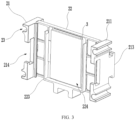
- FIG. 3 is a schematic structural diagram of a positioning member and a cushion assembly of a constraining apparatus that are in an assembled state according to some embodiments of this application; and
- FIG. 4 is a schematic structural diagram of a positioning member and a cushion assembly of a constraining apparatus that are in a disassembled state according to some embodiments of this application.
- the positioning member 20 includes two positioning pieces 21 and a restricting piece 22.
- the two positioning pieces 21 are disposed opposite each other in the second direction Y, and are movably connected to the guide assembly 12 in the first direction X.
- the second direction Y is perpendicular to the first direction X.
- the restricting piece 22 is detachably connected between the two positioning pieces 21, and the cushion assembly 3 is disposed on the restricting piece 22.
- An accommodating space 4 is formed between the restricting pieces 22 of adjacent two of the positioning members 20, and the cushion assembly 3 is configured to be disposed between the restricting pieces 22 and the battery cells 10.
- the positioning pieces 21 have a positioning function. Specifically, it can be understood that, in the first direction X, two adjacent positioning pieces 21 abut against each other such that two adjacent of the positioning members 20 abut against each other. Therefore, the accommodating space 4 for accommodating the battery cells 10 can be formed between adj acent two of the restricting pieces 22 through the positioning between the two positioning pieces 21.
- the positioning piece 21 may be in various shapes, for example, being a rectangular plate structure or a square plate structure.
- the positioning piece 21 has a specific length in the first direction X, and the length can be set according to the volume of the battery cell 10.
- the positioning piece 21 is movably connected to the guide assembly 12 in the first direction X in various connection forms, for example, in a shaft hole sliding fit or a sliding wheel connection. For example, in FIG. 2 , the positioning piece 21 is connected to the guide assembly 12 by a shaft hole sliding fit.
- the restricting piece 22 is provided with a cushion assembly 3, and the cushion assembly 3 may be disposed on one side of the restricting piece 22 or on two sides of the restricting piece 22 that are opposite each other in the first direction X.
- the cushion assembly 3 and the restricting pieces 22 may be connected in various connection forms, for example, bonding and fitting.
- the positioning member 20 includes a restricting piece 22 and two positioning pieces 21, and the restricting piece 22 is detachably connected to the two positioning pieces 21.
- Such detachable connection facilitates the disassembly of the restricting piece 22.
- the shape of the constraining apparatus can be changed to adapt the accommodating space 4 to the battery cells 10, such that the battery cells 10 of different types can be replaced quickly, improving the versatility and convenience of use of the constraining apparatus.
- thin restricting pieces 22 can be used; and under the condition that thickness of the battery cell 10 is small, thick restricting pieces 22 can be used.
- some of the restricting pieces 22 may alternatively be disassembled such that a plurality of accommodation spaces 4 can be merged to form a larger accommodating space for accommodating the battery cell 10.
- the restricting pieces 22 are detachably connected to the two opposite positioning pieces 21, and such detachable connection may be in various forms, for example, snap-fit connection, pinshaft connection, or threaded connection.
- the positioning piece 21 is provided with a first positioning hole
- the restricting piece 22 is provided with a second positioning hole matching the first positioning hole
- internal threads are provided on inner walls of the first positioning hole and the second positioning hole, and the positioning piece 21 and the restricting piece 22 can be fixedly connected through these screws.
- a sliding slot is formed on the restricting piece 22
- a sliding block matching with the sliding slot is formed on the positioning piece 21
- the restricting piece 22 matches the positioning piece 21 through the sliding block and the sliding slot.
- the restricting piece 22 includes a body 221 and two first convex portions 222 connected to the body 221, where the two first convex portions 222 respectively protrude in a direction towards the positioning pieces 21 with respect to the body 221, and the body 221 is connected to the cushion assembly 3; and the positioning piece 21 includes a main body 211 and first concave portions 212, where the first concave portion 212 is depressed in a direction away from the restricting pieces 22 with respect to the main body 211, and the first concave portion 212 is fitted to the first convex portion 222.
- a plurality of through holes 221a may be provided on the body 221; and a plurality of protrusions 31 may be provided on a side of the cushion assembly 3 facing the body 221, where the protrusions 31 are embedded in the through holes 221a.
- the cushion assembly 3 can be detachably connected to the body 221, thereby facilitating the disassembly and replacement of the cushion assembly 3.
- such a connection form, in which the protrusions 31 match the through holes 221a simplifies the structure, improves stability, and reduces manufacturing costs.
- the positioning piece 21 includes a main body 211, a second convex portion 213, and a second concave portion 214, where the second convex portion 213 is connected to the main body 211 and protrudes in the first direction X with respect to the main body 211; the second concave portion 214 is connected to the main body 211, recessed in the first direction X with respect to the main body 211, and disposed opposite the second convex portion 213 in the first direction X; and in the first direction X, the second convex portion 213 of one of the two adjacent positioning pieces 21 is fitted to the second concave portion 214 of the other one of the two adjacent positioning pieces 21.
- the second convex portion 213 may have various structural forms, for example, it may be a spherical convex platform structure, an arc-shaped convex platform structure, or a square convex platform structure.
- the second concave portion 214 may be set according to the shape of the second convex portion 213. For example, if the second convex portion 213 is a spherical convex platform structure, the second concave portion 214 is correspondingly configured as a spherical cavity with an opening. In some examples, as shown in FIG. 3 and FIG.
- the second convex portion 213 may be set as a T-shaped convex platform structure, the second concave portion 214 may be set as a T-shaped concave structure, and the two are fitted through the T-shaped structure.
- This type of connection has higher connection strength and detachment is not easy to occur.
- the two adjacent positioning pieces 21 are disposed in a fitting structure form between the convex portion and the concave portion, which can enhance the structural stability between the two adjacent positioning pieces when the positioning pieces 21 abut against each other, thereby enhancing the structural stability of the constraining apparatus during operation. Moreover, when the constraining apparatus is in a non-working state, the positioning pieces 21 can be fitted to each other to prevent movement of the positioning pieces 21. In this case, the positioning assembly 2 is integral, improving the overall structural integrity of the constraining apparatus.
- the restricting piece 22 includes a body 221 and a third convex portion 223 connected to the body 221, where the third convex portion 223 protrudes in the first direction X with respect to the body 221 and encloses a first cavity 224, the accommodating space 4 is formed between the first cavities 224 of adjacent two of the positioning members 20, and the cushion assembly 3 is disposed in the first cavity 224.
- the third convex portion 223 protrudes in the first direction X and encloses the first cavity 224.
- the third convex portion 223 may be configured as a multi-sided convex structure.
- the third convex portion 223 is a three-sided convex structure, where two of the three sides are opposite in the second direction Y, and the another side connects the two opposite sides and is disposed close to the support assembly 11.
- the three-sided convex structure can ensure that the battery cell 10 can be constrained and positioned without affecting loading and unloading of the battery cell 10. This enhances the structural stability of the constraining apparatus constraining the battery cell 10.
- a supporting piece may be additionally disposed on a side, of the third convex portion 223, close to the support assembly 11, and the supporting piece is connected to the third convex portion 223 and supports the third convex portion 223. This can enhance the structural strength of the third convex portion 223 and enhance the structural stability of the constraining apparatus when the constraining apparatus constrains the battery cell 10.
- the first cavity 224 is enclosed by the third convex portion 223, and the cushion assembly 3 is disposed in the first cavity 224.
- the third convex portion 223 can also constrain the cushion assembly 3 to a certain extent, which enhances stability of the connection between the third convex portion 223 and the positioning members 20.
- the guide assembly 12 includes a plurality of guide shafts 121 extending in the first direction X, where the plurality of guide shafts 121 are spaced apart from each other in a direction perpendicular to the first direction X; and the positioning member 20 includes a plurality of movable portions 23, where each of the movable portions 23 is movably connected to its corresponding guide shaft 121.
- the plurality of guide shafts 121 are spaced apart from each other in the direction perpendicular to the first direction X, which can be understood that some of the plurality of guide shafts 121 are spaced apart from each other in the second direction Y, and the rest of the guide shafts 121 are spaced apart from each other in a third direction Z.
- the first direction X, the second direction Y, and the third direction Z are perpendicular to each other.
- the positioning member 20 includes a plurality of movable portions 23, where the movable portion 23 may be in various structural forms, for example, it may be a cylindrical through hole, a polygonal through hole, or the like, or certainly may be a semi-cylindrical through hole (as shown in FIG. 4 ), and the guide shaft 121 passes through the through hole.
- the shape of the movable portion 23 can be selected according to the shape of the guide shaft 121. For example, if the guide shaft 121 is a cylindrical strip structure, the movable portion 23 may be configured as a cylindrical through hole; or if the guide shaft 121 is configured as a square strip structure, the movable portion 23 may be configured as a square through hole.
- the guide assembly 12 includes a plurality of guide shafts 121, which can enhance the stationarity of the positioning member 20 moving along the guide assembly 12 and enhance the structural stability of the constraining apparatus.
- the guide shafts 121 feature simple structure, ease of manufacturing and molding, and low cost.
- the constraining apparatus further includes a holding assembly 5 and a jacking assembly 6.
- the holding assembly 5 is disposed on a side of the end plate assembly 13 close to the positioning member 20; and the jacking assembly 6 is disposed on the end plate assembly 13 and can move in the first direction X with respect to the end plate assembly 13.
- the jacking assembly 6 is locked with the end plate assembly 13, and the holding assembly 5 abuts against the jacking assembly 6 and the positioning member 20; and in the second state, the jacking assembly 6 is locked with the end plate assembly 13, and the jacking assembly 6 is disengaged from the holding assembly 5.
- the holding assembly 5 can push the positioning member 20 to move in the first direction X, which means that the holding assembly 5 can also move in the first direction X.
- various positional relationships may be present between the holding assembly 5 and the guide assembly 12.
- the holding assembly 5 may not be connected to the guide assembly 12 but is only displaced with respect to the guide assembly 12; or may be movably connected to the guide assembly 12, and moves in the first direction X along the guide assembly 12. If the holding assembly 5 is movably connected to the guide assembly 12, its movement stationarity can be better when the holding assembly 5 moves in the first direction X, which can enhance the overall structural stability of the constraining apparatus.
- the constraining apparatus When the holding assembly 5 pushes the positioning member 20 to move and makes all adjacent positioning members 20 abut against each other, the constraining apparatus is in the first state, and in this case the holding assembly 5 can maintain a pressing force on the positioning assembly 2, where the pressing force can be transferred to all the positioning members 20 in sequence, such that the battery cell 10 can be constrained by the positioning members 20 so as to discharge the excess gas inside.
- the holding assembly 5 is disposed on a side of the end plate assembly 13 close to the positioning member 20.
- the holding assembly 5 and the end plate assembly 13 are disposed in various forms.
- the holding assembly 5 and the end plate assembly 13 may not be connected, and the two serve as two independent structures that do not interfere with each other; or the holding assembly 5 and the end plate assembly 13 are detachably connected, when the constraining apparatus is in the second state, the two are connected to each other, when the constraining apparatus is in the first state, the two are detached.
- Advantages of such arrangement lie in that the holding assembly 5 and the base 1 can be integrated when the constraining apparatus is in a non-working state, so as to avoid free movement of the holding assembly 5 and improve the structural integrity of the constraining apparatus.
- the two can have various connection forms, for example, threaded connection or snap-fit connection.
- a convex portion is provided on a side of the holding assembly 5 facing the end plate assembly 13
- a concave portion matching the convex portion is provided on a side of the end plate assembly 13 facing the holding assembly 5, where the convex portion can be engaged with the concave portion, such that the holding assembly 5 can be fitted to the end plate assembly 13.
- the end plate assembly 13 includes a plurality of mounting portions 131, where the plurality of mounting portions 131 are spaced apart from each other, and the jacking assembly 6 is disposed on the mounting portion 131.
- the jacking assembly 6 and the mounting portion 131 can have various structure forms.
- the jacking assembly 6 is a jacking rod
- the mounting portion 131 is a mounting hole, where the jacking rod and the mounting hole are in a clearance fit.
- a plurality of pin holes are provided on the jacking rod, and the plurality of pin holes are spaced part from each other in the first direction X.
- the mounting portion 131 is a threaded hole with internal threads
- the jacking assembly 6 is a screw rod with external threads
- the jacking assembly 6 and the mounting portion 131 are connected by threads.
- the jacking assembly 6 can be screwed in reverse to move in the first direction X away from the holding assembly 5, and the jacking assembly 6 and the holding assembly 5 are released from the abutting state. In this case, the constraining apparatus is in the second state.
- a plurality of jacking assemblies 6 are mounted and disposed on the plurality of mounting portions 131, and the plurality of jacking assemblies 6 abut against the holding assemblies 5, which can improve the effect of compressing the holding assemblies 5, so as to improve the effect of constraining the battery cell 10.
- the plurality of mounting portions 131 may alternatively be spaced apart from each other in the second direction Y, and the number and locations of the mounting portions 131 may be selected according to needs, which are not limited in this application.
- the holding assembly 5 includes a plurality of matching portions (not shown in the figure) disposed opposite the mounting portion 131 in the first direction X; in the first state, the jacking assembly 6 abuts against the matching portions; and in the second state, the jacking assembly 6 is disengaged from the matching portions.
- the matching portion is in direct contact with the jacking assembly 6, and can be disposed based on the structure of the jacking assembly 6.
- the matching portion may be configured as a circular blind hole; or if the jacking assembly 6 is a square strip structure, the matching portion may be configured as a square blind hole.
- the holding assembly 5 is provided with the matching portion that matches the jacking assembly 6, which can improve the abutment stability between the jacking assembly 6 and the holding assembly 5 during abutment against therebetween, reduce the possibility of the displacement of the jacking assembly 6, and improve the overall structural stability of the constraining apparatus.
- a wear-resistant piece may be mounted on the matching portion so as to reduce the damage to the holding assembly 5.
- the wear-resistant piece can be made of various materials, for example, wear-resistant rubber, wear-resistant resin, or ceramic materials.
- a flexible member may also be provided at an end of the jacking assembly 6 in contact with the matching portion, so as to reduce damage to the holding assembly 5.
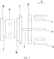
- FIG. 5 is a schematic structural diagram of a constraining device according to some embodiments of this application.
- the constraining device includes the constraining apparatus according to any one of the embodiments and an a pressurizing apparatus 7, where the pressurizing apparatus 7 is configured to exert an acting force on the positioning assembly 2 in a first sub-direction X1, such that the constraining apparatus is in the first state and adj acent two of the positioning members 20 abut against each other.
- the first sub-direction X1 is unidirectional, and the first sub-direction X1 is parallel to the first direction X.
- the constraining device provided in this embodiment of this application includes a pressurizing apparatus 7.
- the pressurizing apparatus 7 exerts an acting force on the positioning assembly 2
- the pressurizing apparatus 7 can be connected to the positioning assembly 2.
- the connection therebetween may be in various forms, for example, direct connection, or indirect connection.
- a third connecting piece is disposed to connect the pressurizing apparatus 7 and the positioning assembly 2.
- the pressurizing apparatus 7 is disposed to exert pressure on the positioning assembly 2, such that human intervention can be reduced. This raises the automation level of the constraining device and improves the constraining efficiency.
- the constraining apparatus further includes the holding assembly 5 and the jacking assembly 6; and the constraining device further includes a screw tightening apparatus 9, where the screw tightening apparatus 9 is configured to connect the jacking assembly 6, so as to drive the jacking assembly 6 to rotate and push the holding assembly 5 to move in the first sub-direction X1.
- the jacking assembly 6 can be threaded with both the screw tightening apparatus 9 and the end plate assembly 13.
- An end of the jacking assembly 6 away from the holding assembly 5 may be provided with internal threads, and an end of the screw tightening apparatus 9 facing the end plate assembly 13 may be provided with external threads, such that the screw tightening apparatus 9 can be screwed and fixedly connected to the jacking assembly 6 by rotating itself.
- the screw tightening apparatus 9 can drive the jacking assembly 6 to rotate accordingly and make the jacking assembly 6 move back and forth in the first direction X through its own forward rotation and reverse rotation.
- the jacking assembly 6 can abut against the holding assembly 5 or no longer abuts against the holding assembly 5, such that the constraining apparatus can switch between the first state and the second state.
- the screw tightening apparatus 9 can also release the connection with the jacking assembly 6 by rotating itself.
- Advantages of disposing the screw tightening apparatus 9 lie in that after the pressurizing apparatus 7 compresses the positioning assembly 2, the holding assembly 5 can be compressed against one end of the positioning assembly 2 through matching of the screw tightening apparatus 9 and the jacking assembly 6, and the compressing effect is maintained through the fixing action of the threaded connection. In this case, the pressurizing apparatus 7 can be removed, and only the screw tightening apparatus 9 applies pressure on the positioning assembly 2, which can reduce the power consumption of the constraining device.
- the constraining device further includes a pressure relief apparatus 8, where the pressure relief apparatus 8 is configured to exert an acting force on the positioning assembly 2 in a direction opposite the first sub-direction X1, such that the constraining apparatus is in the second state and the positioning members 20 are spaced apart from each other in the first direction X.
- the pressure relief apparatus 8 When the pressure relief apparatus 8 applies a force on the positioning assembly 2, the pressure relief apparatus 8 can be connected to the positioning assembly 2.
- the pressure relief apparatus 8 and the positioning assembly 2 can have various connection forms, for example, direct connection or indirect connection.
- a fourth connecting piece is disposed to connect the pressure relief apparatus 8 and the positioning assembly 2.
- the pressure relief apparatus 8 is disposed such that human intervention can be reduced in releasing the battery cell 10 by the constraining apparatus. This raises the automation level of the constraining device and improves the operating efficiency.
- the constraining apparatus includes a base 1, a positioning assembly 2, and a cushion assembly 3.
- the base 1 includes a support assembly 11, a guide assembly 12, and two end plate assemblies 13, where the two end plate assemblies 13 are respectively connected to two ends of the support assembly 11 that are opposite each other in a first direction X.
- the guide assembly 12 extends in the first direction X and is connected to the two end plate assemblies 13.
- the positioning assembly 2 includes a plurality of positioning members 20 arranged in sequence in the first direction X and located between two end plate assemblies 13, where the plurality of positioning members 20 are movably connected to the guide assembly 12 in the first direction X.
- the positioning member 20 includes two positioning pieces 21 and a restricting piece 22, where the two positioning pieces 21 are disposed opposite each other in the second direction Y, and are movably connected to the guide assembly 12 in the first direction X, and the second direction Y is perpendicular to the first direction X.
- the restricting piece 22 is detachably connected between the two positioning pieces 21.
- the cushion assembly 3 is disposed on the restricting piece 22, and an accommodating space 4 is formed between the restricting pieces 22 of adjacent two of the positioning members 20, and the cushion assembly 3 is configured to be disposed between the restricting pieces 22 and the battery cells 10.
- the constraining apparatus includes a first state and a second state, where in the first state, the two adjacent positioning pieces 21 of adjacent two of the positioning members 20 abut against each other, such that an accommodating space 4 for accommodating a battery cell 10 is formed between the restricting pieces 22 of the adjacent two of the positioning members 20, and the cushion assembly 3 is configured to abut against the battery cell 10 and positioning members 20; and in the second state, the positioning pieces 21 of the plurality of positioning members 20 are spaced apart from each other in the first direction X.
- the constraining apparatus provided in this embodiment of this application includes a first state and a second state.
- the first state is a state of exerting constraint on the battery cell 10 by the constraining apparatus
- the second state is a state of releasing constraint on the battery cell.
- the constraining apparatus can switch between the first state and the second state by changing positions of the positioning members 20.
- the positioning members 20 When the constraining apparatus is in the first state, the positioning members 20 abut against each other, and the battery cell 10 is compressed, which prompts the battery cell 10 to discharge gas.
- the constraining apparatus is in the second state, gaps are present between the positioning members 20, the battery cell 10 is not subject to the constraining force, and the battery cell 10 can be easily loaded and unloaded.
- the cushion assembly 3 Under the condition that the constraining apparatus of this embodiment of this application is in the first state, the cushion assembly 3 abuts against the battery cell 10 and the positioning members 20, and the cushion assembly 3 has an elastic force, which can be converted into a constraining force on the battery cell 10.
- the battery cell 10 is always subject to the constraining force applied by the cushion assembly 3 in the constraining process, and the gas inside the battery cell 10 can be fully discharged.
- the constraining apparatus of this embodiment of this application greatly improves the effect of constraining the battery cell 10 and decreases the defect rate of producing battery cells 10.
- the positioning member 20 includes a restricting piece 22 and two positioning pieces 21, and the restricting piece 22 is detachably connected to the two positioning pieces 21.
- Such detachable connection facilitates the disassembly of the restricting piece 22.
- the shape of the constraining apparatus can be changed to adapt the accommodating space 4 to the battery cells 10, such that the battery cells 10 of different types can be replaced quickly. This improves the versatility and convenience of use of the constraining apparatus.
Landscapes
- Chemical & Material Sciences (AREA)
- Chemical Kinetics & Catalysis (AREA)
- Electrochemistry (AREA)
- General Chemical & Material Sciences (AREA)
- Battery Mounting, Suspending (AREA)
- Sealing Battery Cases Or Jackets (AREA)
Claims (12)
- Appareil de contrainte destiné à contraindre un élément de batterie, dans lequel l'appareil de contrainte comprend :une base (1) comprenant un ensemble de support (11), un ensemble de guidage (12) et deux ensembles de plaque d'extrémité (13), dans lequel les deux ensembles de plaque d'extrémité (13) sont reliés respectivement aux deux extrémités de l'ensemble de support (11) qui sont opposées l'une à l'autre dans une première direction (X), et l'ensemble de guidage (12) s'étend dans la première direction (X) et est relié aux deux ensembles de plaque d'extrémité (13) ;un ensemble de positionnement (2) comprenant une pluralité d'éléments de positionnement (20) disposés en séquence dans la première direction (X) et situés entre les deux ensembles de plaque d'extrémité (13), dans lequel la pluralité d'éléments de positionnement (20) sont reliés de manière mobile à l'ensemble de guidage (12) dans la première direction (X), et deux éléments adjacents des éléments de positionnement (20) sont ajustés l'un sur l'autre dans la première direction (X) ; etun ensemble de coussin (3) disposé sur au moins un des deux côtés de l'élément de positionnement (20) qui sont opposés l'un à l'autre dans la première direction (X) ;dans lequel l'appareil de contrainte comprend un premier état et un deuxième état ; dans le premier état, deux éléments adjacents des éléments de positionnement (20) viennent en butée l'un contre l'autre de telle sorte qu'un espace de logement (4) pour loger un élément de batterie (10) est formé entre les deux éléments adjacents des éléments de positionnement (20), et l'ensemble de coussin (3) est configuré pour venir en butée contre l'élément de batterie (10) et les éléments de positionnement (20) ; et dans le deuxième état, la pluralité d'éléments de positionnement (20) sont espacés l'un de l'autre dans la première direction (X) ;dans lequel l'élément de positionnement (20) comprend :deux pièces de positionnement (21) disposées à l'opposé l'une de l'autre dans une deuxième direction (Y), dans lequel les deux pièces de positionnement (21) sont reliées de manière mobile à l'ensemble de guidage (12) dans la première direction (X), et la deuxième direction (Y) est perpendiculaire à la première direction (X) ; etune pièce de restriction (22) reliée de manière détachable entre les deux pièces de positionnement (21), dans lequel l'ensemble de coussin (3) est disposé sur la pièce de restriction (22) ;dans lequel un espace de logement (4) est formé entre les pièces de restriction (22) de deux éléments adjacents des éléments de positionnement (20), et l'ensemble de coussin (3) est configuré pour être disposé entre les pièces de restriction (22) et les éléments de batterie (10) ;dans lequel l'ensemble de guidage (12) comprend une pluralité d'arbres de guidage (121) s'étendant dans la première direction (X), et la pluralité d'arbres de guidage (121) sont espacés les uns des autres dans une direction perpendiculaire à la première direction (X) ; etl'élément de positionnement (20) comprend une pluralité de parties mobiles, et chacune des parties mobiles est reliée de manière mobile à son arbre de guidage (121) correspondant ; etdans lequel l'appareil de contrainte comprend en outre :un ensemble de maintien (5) disposé sur un côté de l'ensemble de plaque d'extrémité (13) à proximité de l'élément de positionnement (20) ; etun ensemble de levage (6) disposé sur l'ensemble de plaque d'extrémité (13) et capable de se déplacer dans la première direction (X) par rapport à l'ensemble de plaque d'extrémité (13) ;dans lequel dans le premier état, l'ensemble de levage (6) est verrouillé avec l'ensemble de plaque d'extrémité (13), et l'ensemble de maintien (5) vient en butée contre l'ensemble de levage (6) et l'élément de positionnement (20) ;
etdans le deuxième état, l'ensemble de levage (6) est verrouillé avec l'ensemble de plaque d'extrémité (13), et l'ensemble de levage (6) est désengagé de l'ensemble de maintien (5). - Appareil de contrainte selon la revendication 1, caractérisé en ce que l'ensemble de positionnement (2) est fourni en pluralité, dans lequel la pluralité d'ensembles de positionnement (2) sont disposés successivement dans une deuxième direction (Y), et la deuxième direction (Y) est perpendiculaire à la première direction (X).
- Appareil de contrainte selon la revendication 1, caractérisé en ce que la pièce de restriction (22) comprend un corps (221) et deux premières parties convexes (222) reliées au corps (221), les deux premières parties convexes (222) font saillie respectivement dans une direction vers les pièces de positionnement (21) par rapport au corps (221), et le corps (221) est relié à l'ensemble de coussin (3) ; et
la pièce de positionnement (21) comprend un corps principal (211) et des premières parties concaves (212), dans lequel la première partie concave (212) est enfoncée dans une direction à l'écart de la pièce de restriction (22) par rapport au corps principal (211), et les premières parties concaves (212) sont ajustées aux premières parties convexes (222). - Appareil de contrainte selon la revendication 1, caractérisé en ce que la pièce de positionnement (21) comprend :un corps principal (211) ;une deuxième partie convexe (213) reliée au corps principal (211) et faisant saillie dans la première direction (X) par rapport au corps principal (211) ; etune deuxième partie concave (214) reliée au corps principal (211), enfoncée dans la première direction (X) par rapport au corps principal (211), et disposée à l'opposé de la deuxième partie convexe (213) dans la première direction (X) ; etdans la première direction (X), la deuxième partie concave (213) d'une des deux pièces de positionnement (21) adjacentes est ajustée à la deuxième partie concave (214) de l'autre des deux pièces de positionnement (21) adjacentes.
- Appareil de contrainte selon la revendication 1, caractérisé en ce que la pièce de restriction (22) comprend un corps (221) et une troisième partie convexe (223) reliée au corps (221), dans lequel la troisième partie convexe (223) fait saillie dans la première direction (X) par rapport au corps (221) et entoure une première cavité (224), l'espace de logement (4) est formé entre les premières cavités de deux éléments adjacents des éléments de positionnement (20), et l'ensemble de coussin (3) est disposé dans la première cavité (224).
- Appareil de contrainte selon la revendication 3, caractérisé en ce que :une pluralité de trous traversants (221a) sont prévus sur le corps (221) ; etune pluralité de parties faisant saillie (31) sont prévues sur un côté de l'ensemble de coussin (3) faisant face au corps (221) et sont incorporées dans les trous traversants (221a).
- Appareil de contrainte selon la revendication 1, caractérisé en ce que l'ensemble de maintien (5) est relié de manière mobile à l'ensemble de guidage (12) dans la première direction (X).
- Appareil de contrainte selon la revendication 1, caractérisé en ce que dans le deuxième état, l'ensemble de maintien (5) est engagé avec l'ensemble de plaque d'extrémité (13).
- Appareil de contrainte selon la revendication 1, caractérisé en ce que l'ensemble de plaque d'extrémité (13) comprend une pluralité de parties de montage (131), la pluralité de parties de montage (131) sont espacées les unes des autres, et l'ensemble de levage (6) est disposé sur la partie de montage (131) ;en option, l'ensemble de maintien (5) comprend une pluralité de parties correspondantes disposées à l'opposé des parties de montage (131) dans la première direction (X) ;dans lequel dans le premier état, l'ensemble de levage (6) vient en butée contre la partie correspondante ; etdans le deuxième état, l'ensemble de levage (6) est désengagé de la partie correspondante.
- Dispositif de contrainte, caractérisé en ce qu'il comprend :l'appareil de contrainte selon l'une quelconque des revendications 1 à 6 ; etun appareil de pressurisation (7), dans lequel l'appareil de pressurisation (7) est configuré pour exercer une force d'action sur l'ensemble de positionnement (2) dans une première sous-direction (X1) de telle sorte que l'appareil de contrainte est dans le premier état et deux éléments adjacents des éléments de positionnement (20) viennent en butée l'un contre l'autre, et la première sous-direction (X1) est parallèle à la première direction (X).
- Dispositif de contrainte selon la revendication 10, caractérisé en ce que le dispositif de contrainte comprend en outre :
un appareil de relâchement de pression (8), dans lequel l'appareil de relâchement de pression (8) est configuré pour exercer une force d'action sur l'ensemble de positionnement (2) dans une direction opposée à la première sous-direction (X1) de telle sorte que l'appareil de contrainte est dans le deuxième état et les éléments de positionnement (20) sont espacés les uns des autres dans la première direction (X). - Dispositif de contrainte selon la revendication 10, caractérisé en ce que :l'appareil de contrainte comprend en outre un ensemble de maintien (5) et un ensemble de levage (6) ; etle dispositif de contrainte comprend en outre un appareil de serrage de vis (9), dans lequel l'appareil de serrage de vis (9) est configuré pour être relié à l'ensemble de levage (6) de manière à entraîner l'ensemble de levage (6) pour tourner et pousser l'ensemble de maintien (5) pour qu'il se déplace dans la première sous-direction (X1).
Priority Applications (1)
| Application Number | Priority Date | Filing Date | Title |
|---|---|---|---|
| EP24218926.4A EP4503290A3 (fr) | 2022-09-19 | 2023-03-24 | Appareil de contrainte et dispositif de contrainte |
Applications Claiming Priority (1)
| Application Number | Priority Date | Filing Date | Title |
|---|---|---|---|
| CN202222468050.5U CN217903212U (zh) | 2022-09-19 | 2022-09-19 | 拘束装置和拘束设备 |
Related Child Applications (2)
| Application Number | Title | Priority Date | Filing Date |
|---|---|---|---|
| EP24218926.4A Division-Into EP4503290A3 (fr) | 2022-09-19 | 2023-03-24 | Appareil de contrainte et dispositif de contrainte |
| EP24218926.4A Division EP4503290A3 (fr) | 2022-09-19 | 2023-03-24 | Appareil de contrainte et dispositif de contrainte |
Publications (2)
| Publication Number | Publication Date |
|---|---|
| EP4340108A1 EP4340108A1 (fr) | 2024-03-20 |
| EP4340108B1 true EP4340108B1 (fr) | 2025-01-29 |
Family
ID=84109139
Family Applications (2)
| Application Number | Title | Priority Date | Filing Date |
|---|---|---|---|
| EP23163892.5A Active EP4340108B1 (fr) | 2022-09-19 | 2023-03-24 | Appareil de contrainte et dispositif de contrainte |
| EP24218926.4A Pending EP4503290A3 (fr) | 2022-09-19 | 2023-03-24 | Appareil de contrainte et dispositif de contrainte |
Family Applications After (1)
| Application Number | Title | Priority Date | Filing Date |
|---|---|---|---|
| EP24218926.4A Pending EP4503290A3 (fr) | 2022-09-19 | 2023-03-24 | Appareil de contrainte et dispositif de contrainte |
Country Status (6)
| Country | Link |
|---|---|
| US (1) | US20240097265A1 (fr) |
| EP (2) | EP4340108B1 (fr) |
| CN (1) | CN217903212U (fr) |
| ES (1) | ES3015542T3 (fr) |
| HU (1) | HUE070885T2 (fr) |
| PL (1) | PL4340108T3 (fr) |
Families Citing this family (3)
| Publication number | Priority date | Publication date | Assignee | Title |
|---|---|---|---|---|
| EP4431407A4 (fr) * | 2023-01-31 | 2025-11-12 | Contemporary Amperex Technology Hong Kong Ltd | Plaque de séparation, ensemble plateau et dispositif de traitement de batterie |
| CN219811540U (zh) * | 2023-07-04 | 2023-10-10 | 宁德时代新能源科技股份有限公司 | 拘束结构及电池拘束装置 |
| CN223181189U (zh) * | 2024-07-11 | 2025-08-01 | 宁德时代新能源科技股份有限公司 | 拘束托盘以及化成设备 |
Citations (1)
| Publication number | Priority date | Publication date | Assignee | Title |
|---|---|---|---|---|
| EP3121868A1 (fr) * | 2014-03-17 | 2017-01-25 | Nissan Motor Co., Ltd. | Dispositif de mise sous pression pour cellules de batterie |
Family Cites Families (6)
| Publication number | Priority date | Publication date | Assignee | Title |
|---|---|---|---|---|
| JP4508221B2 (ja) * | 2007-08-27 | 2010-07-21 | 豊田合成株式会社 | 組電池装置 |
| DE102013020860A1 (de) * | 2013-12-12 | 2015-06-18 | Daimler Ag | Zellblock für eine Batterie |
| JP6413822B2 (ja) * | 2015-02-16 | 2018-10-31 | 株式会社豊田自動織機 | 電池モジュール及び電池モジュールの製造方法 |
| KR102271384B1 (ko) * | 2015-04-15 | 2021-06-29 | 에스케이이노베이션 주식회사 | 이차 전지 팩 |
| CN107851757B (zh) * | 2015-07-30 | 2020-11-13 | 三洋电机株式会社 | 电源装置与包括该电源装置的电源系统及电池单元用分隔件 |
| JP6990072B2 (ja) * | 2017-09-12 | 2022-01-12 | 株式会社ブルーエナジー | 蓄電装置 |
-
2022
- 2022-09-19 CN CN202222468050.5U patent/CN217903212U/zh active Active
-
2023
- 2023-03-24 PL PL23163892.5T patent/PL4340108T3/pl unknown
- 2023-03-24 EP EP23163892.5A patent/EP4340108B1/fr active Active
- 2023-03-24 EP EP24218926.4A patent/EP4503290A3/fr active Pending
- 2023-03-24 ES ES23163892T patent/ES3015542T3/es active Active
- 2023-03-24 HU HUE23163892A patent/HUE070885T2/hu unknown
- 2023-03-30 US US18/193,027 patent/US20240097265A1/en active Pending
Patent Citations (1)
| Publication number | Priority date | Publication date | Assignee | Title |
|---|---|---|---|---|
| EP3121868A1 (fr) * | 2014-03-17 | 2017-01-25 | Nissan Motor Co., Ltd. | Dispositif de mise sous pression pour cellules de batterie |
Also Published As
| Publication number | Publication date |
|---|---|
| US20240097265A1 (en) | 2024-03-21 |
| ES3015542T3 (en) | 2025-05-06 |
| EP4503290A2 (fr) | 2025-02-05 |
| EP4340108A1 (fr) | 2024-03-20 |
| HUE070885T2 (hu) | 2025-07-28 |
| EP4503290A3 (fr) | 2025-04-02 |
| PL4340108T3 (pl) | 2025-05-26 |
| CN217903212U (zh) | 2022-11-25 |
Similar Documents
| Publication | Publication Date | Title |
|---|---|---|
| EP4340108B1 (fr) | Appareil de contrainte et dispositif de contrainte | |
| US20110262785A1 (en) | Battery module | |
| JP6994674B2 (ja) | 蓄電装置 | |
| CN111916600B (zh) | 一种电池模组 | |
| JP6644230B1 (ja) | 充放電試験機 | |
| US8802260B2 (en) | Separation method of secondary battery | |
| EP4057425A1 (fr) | Dispositif de pression, dispositif de fabrication de module de batterie et procédé de fabrication | |
| JP2008535175A (ja) | 密閉型バッテリー用ケーシング | |
| KR20160123091A (ko) | 이차 전지 팩 | |
| JP2008277303A (ja) | 燃料電池スタック構造用エンドプレート | |
| KR20190072289A (ko) | 파우치형 이차전지의 충방전용 가압 지그 | |
| KR102873734B1 (ko) | 에너지 저장 시스템 | |
| KR102601592B1 (ko) | 이차 전지 | |
| US20230395885A1 (en) | Battery module and electronic device | |
| KR20070101025A (ko) | 전지 모듈 | |
| CN107994175B (zh) | 一种电动摩托车电池箱组 | |
| JPH05190162A (ja) | バッテリハウジングアセンブリ | |
| CN116454519A (zh) | 包括表面压力保持结构的电池包 | |
| CN101990014A (zh) | 电池顶出装置及具该电池顶出装置的便携式电子装置 | |
| KR20220040931A (ko) | 로드 셀을 포함하는 전지 셀 가압 지그, 및 이를 이용한 전지 셀 가압 방법과 스웰링 측정 방법 | |
| FR2884354A3 (fr) | Structure de logement pour batterie d'ordinateur portable | |
| FR3138738A1 (fr) | Module de stockage électrique équipé d’un dispositif de maintien en compression des cellules de stockage et stockeur d’énergie électrique l’incorporant | |
| WO2008089553A1 (fr) | Système de compression d'empilement de piles à combustible | |
| CN223671038U (zh) | 电池单体的测试夹具 | |
| CN216529204U (zh) | 一种电芯固定结构 |
Legal Events
| Date | Code | Title | Description |
|---|---|---|---|
| PUAI | Public reference made under article 153(3) epc to a published international application that has entered the european phase |
Free format text: ORIGINAL CODE: 0009012 |
|
| STAA | Information on the status of an ep patent application or granted ep patent |
Free format text: STATUS: REQUEST FOR EXAMINATION WAS MADE |
|
| 17P | Request for examination filed |
Effective date: 20230324 |
|
| AK | Designated contracting states |
Kind code of ref document: A1 Designated state(s): AL AT BE BG CH CY CZ DE DK EE ES FI FR GB GR HR HU IE IS IT LI LT LU LV MC ME MK MT NL NO PL PT RO RS SE SI SK SM TR |
|
| STAA | Information on the status of an ep patent application or granted ep patent |
Free format text: STATUS: EXAMINATION IS IN PROGRESS |
|
| 17Q | First examination report despatched |
Effective date: 20240620 |
|
| RAP1 | Party data changed (applicant data changed or rights of an application transferred) |
Owner name: CONTEMPORARY AMPEREX TECHNOLOGY(HONG KONG) LIMITED |
|
| GRAP | Despatch of communication of intention to grant a patent |
Free format text: ORIGINAL CODE: EPIDOSNIGR1 |
|
| STAA | Information on the status of an ep patent application or granted ep patent |
Free format text: STATUS: GRANT OF PATENT IS INTENDED |
|
| RIC1 | Information provided on ipc code assigned before grant |
Ipc: H01M 10/04 20060101ALN20240919BHEP Ipc: H01M 50/291 20210101ALI20240919BHEP Ipc: H01M 50/264 20210101ALI20240919BHEP Ipc: H01M 50/209 20210101AFI20240919BHEP |
|
| INTG | Intention to grant announced |
Effective date: 20241009 |
|
| RIN1 | Information on inventor provided before grant (corrected) |
Inventor name: WANG, ZHIHUI Inventor name: TANG, SHENG Inventor name: ZHANG, ZHIGUO Inventor name: HUANG, FANGYU Inventor name: ZHAO, JIAYI |
|
| GRAS | Grant fee paid |
Free format text: ORIGINAL CODE: EPIDOSNIGR3 |
|
| GRAA | (expected) grant |
Free format text: ORIGINAL CODE: 0009210 |
|
| STAA | Information on the status of an ep patent application or granted ep patent |
Free format text: STATUS: THE PATENT HAS BEEN GRANTED |
|
| AK | Designated contracting states |
Kind code of ref document: B1 Designated state(s): AL AT BE BG CH CY CZ DE DK EE ES FI FR GB GR HR HU IE IS IT LI LT LU LV MC ME MK MT NL NO PL PT RO RS SE SI SK SM TR |
|
| REG | Reference to a national code |
Ref country code: GB Ref legal event code: FG4D |
|
| REG | Reference to a national code |
Ref country code: CH Ref legal event code: EP |
|
| P01 | Opt-out of the competence of the unified patent court (upc) registered |
Free format text: CASE NUMBER: APP_1296/2025 Effective date: 20250109 |
|
| REG | Reference to a national code |
Ref country code: DE Ref legal event code: R096 Ref document number: 602023001825 Country of ref document: DE |
|
| REG | Reference to a national code |
Ref country code: IE Ref legal event code: FG4D |
|
| PGFP | Annual fee paid to national office [announced via postgrant information from national office to epo] |
Ref country code: AT Payment date: 20250417 Year of fee payment: 3 |
|
| REG | Reference to a national code |
Ref country code: ES Ref legal event code: FG2A Ref document number: 3015542 Country of ref document: ES Kind code of ref document: T3 Effective date: 20250506 |
|
| REG | Reference to a national code |
Ref country code: NL Ref legal event code: MP Effective date: 20250129 |
|
| PG25 | Lapsed in a contracting state [announced via postgrant information from national office to epo] |
Ref country code: NL Free format text: LAPSE BECAUSE OF FAILURE TO SUBMIT A TRANSLATION OF THE DESCRIPTION OR TO PAY THE FEE WITHIN THE PRESCRIBED TIME-LIMIT Effective date: 20250129 |
|
| PG25 | Lapsed in a contracting state [announced via postgrant information from national office to epo] |
Ref country code: RS Free format text: LAPSE BECAUSE OF FAILURE TO SUBMIT A TRANSLATION OF THE DESCRIPTION OR TO PAY THE FEE WITHIN THE PRESCRIBED TIME-LIMIT Effective date: 20250429 |
|
| PG25 | Lapsed in a contracting state [announced via postgrant information from national office to epo] |
Ref country code: FI Free format text: LAPSE BECAUSE OF FAILURE TO SUBMIT A TRANSLATION OF THE DESCRIPTION OR TO PAY THE FEE WITHIN THE PRESCRIBED TIME-LIMIT Effective date: 20250129 |
|
| PGFP | Annual fee paid to national office [announced via postgrant information from national office to epo] |
Ref country code: ES Payment date: 20250401 Year of fee payment: 3 |
|
| REG | Reference to a national code |
Ref country code: LT Ref legal event code: MG9D |
|
| PG25 | Lapsed in a contracting state [announced via postgrant information from national office to epo] |
Ref country code: NO Free format text: LAPSE BECAUSE OF FAILURE TO SUBMIT A TRANSLATION OF THE DESCRIPTION OR TO PAY THE FEE WITHIN THE PRESCRIBED TIME-LIMIT Effective date: 20250429 Ref country code: IS Free format text: LAPSE BECAUSE OF FAILURE TO SUBMIT A TRANSLATION OF THE DESCRIPTION OR TO PAY THE FEE WITHIN THE PRESCRIBED TIME-LIMIT Effective date: 20250529 |
|
| REG | Reference to a national code |
Ref country code: AT Ref legal event code: MK05 Ref document number: 1764409 Country of ref document: AT Kind code of ref document: T Effective date: 20250129 |
|
| PG25 | Lapsed in a contracting state [announced via postgrant information from national office to epo] |
Ref country code: HR Free format text: LAPSE BECAUSE OF FAILURE TO SUBMIT A TRANSLATION OF THE DESCRIPTION OR TO PAY THE FEE WITHIN THE PRESCRIBED TIME-LIMIT Effective date: 20250129 |
|
| PG25 | Lapsed in a contracting state [announced via postgrant information from national office to epo] |
Ref country code: PT Free format text: LAPSE BECAUSE OF FAILURE TO SUBMIT A TRANSLATION OF THE DESCRIPTION OR TO PAY THE FEE WITHIN THE PRESCRIBED TIME-LIMIT Effective date: 20250529 Ref country code: LV Free format text: LAPSE BECAUSE OF FAILURE TO SUBMIT A TRANSLATION OF THE DESCRIPTION OR TO PAY THE FEE WITHIN THE PRESCRIBED TIME-LIMIT Effective date: 20250129 |
|
| PG25 | Lapsed in a contracting state [announced via postgrant information from national office to epo] |
Ref country code: BG Free format text: LAPSE BECAUSE OF FAILURE TO SUBMIT A TRANSLATION OF THE DESCRIPTION OR TO PAY THE FEE WITHIN THE PRESCRIBED TIME-LIMIT Effective date: 20250129 Ref country code: GR Free format text: LAPSE BECAUSE OF FAILURE TO SUBMIT A TRANSLATION OF THE DESCRIPTION OR TO PAY THE FEE WITHIN THE PRESCRIBED TIME-LIMIT Effective date: 20250430 |
|
| PG25 | Lapsed in a contracting state [announced via postgrant information from national office to epo] |
Ref country code: AT Free format text: LAPSE BECAUSE OF FAILURE TO SUBMIT A TRANSLATION OF THE DESCRIPTION OR TO PAY THE FEE WITHIN THE PRESCRIBED TIME-LIMIT Effective date: 20250129 |
|
| REG | Reference to a national code |
Ref country code: HU Ref legal event code: AG4A Ref document number: E070885 Country of ref document: HU |
|
| PG25 | Lapsed in a contracting state [announced via postgrant information from national office to epo] |
Ref country code: SE Free format text: LAPSE BECAUSE OF FAILURE TO SUBMIT A TRANSLATION OF THE DESCRIPTION OR TO PAY THE FEE WITHIN THE PRESCRIBED TIME-LIMIT Effective date: 20250129 |
|
| PG25 | Lapsed in a contracting state [announced via postgrant information from national office to epo] |
Ref country code: SM Free format text: LAPSE BECAUSE OF FAILURE TO SUBMIT A TRANSLATION OF THE DESCRIPTION OR TO PAY THE FEE WITHIN THE PRESCRIBED TIME-LIMIT Effective date: 20250129 |
|
| PG25 | Lapsed in a contracting state [announced via postgrant information from national office to epo] |
Ref country code: DK Free format text: LAPSE BECAUSE OF FAILURE TO SUBMIT A TRANSLATION OF THE DESCRIPTION OR TO PAY THE FEE WITHIN THE PRESCRIBED TIME-LIMIT Effective date: 20250129 |
|
| PG25 | Lapsed in a contracting state [announced via postgrant information from national office to epo] |
Ref country code: MC Free format text: LAPSE BECAUSE OF FAILURE TO SUBMIT A TRANSLATION OF THE DESCRIPTION OR TO PAY THE FEE WITHIN THE PRESCRIBED TIME-LIMIT Effective date: 20250129 |
|
| PG25 | Lapsed in a contracting state [announced via postgrant information from national office to epo] |
Ref country code: IT Free format text: LAPSE BECAUSE OF FAILURE TO SUBMIT A TRANSLATION OF THE DESCRIPTION OR TO PAY THE FEE WITHIN THE PRESCRIBED TIME-LIMIT Effective date: 20250129 |
|
| PG25 | Lapsed in a contracting state [announced via postgrant information from national office to epo] |
Ref country code: CZ Free format text: LAPSE BECAUSE OF FAILURE TO SUBMIT A TRANSLATION OF THE DESCRIPTION OR TO PAY THE FEE WITHIN THE PRESCRIBED TIME-LIMIT Effective date: 20250129 Ref country code: EE Free format text: LAPSE BECAUSE OF FAILURE TO SUBMIT A TRANSLATION OF THE DESCRIPTION OR TO PAY THE FEE WITHIN THE PRESCRIBED TIME-LIMIT Effective date: 20250129 |
|
| PG25 | Lapsed in a contracting state [announced via postgrant information from national office to epo] |
Ref country code: RO Free format text: LAPSE BECAUSE OF FAILURE TO SUBMIT A TRANSLATION OF THE DESCRIPTION OR TO PAY THE FEE WITHIN THE PRESCRIBED TIME-LIMIT Effective date: 20250129 |
|
| PG25 | Lapsed in a contracting state [announced via postgrant information from national office to epo] |
Ref country code: SK Free format text: LAPSE BECAUSE OF FAILURE TO SUBMIT A TRANSLATION OF THE DESCRIPTION OR TO PAY THE FEE WITHIN THE PRESCRIBED TIME-LIMIT Effective date: 20250129 |
|
| REG | Reference to a national code |
Ref country code: DE Ref legal event code: R097 Ref document number: 602023001825 Country of ref document: DE |
|
| PG25 | Lapsed in a contracting state [announced via postgrant information from national office to epo] |
Ref country code: LU Free format text: LAPSE BECAUSE OF NON-PAYMENT OF DUE FEES Effective date: 20250324 |
|
| PLBE | No opposition filed within time limit |
Free format text: ORIGINAL CODE: 0009261 |
|
| STAA | Information on the status of an ep patent application or granted ep patent |
Free format text: STATUS: NO OPPOSITION FILED WITHIN TIME LIMIT |
|
| REG | Reference to a national code |
Ref country code: BE Ref legal event code: MM Effective date: 20250331 |
|
| 26N | No opposition filed |
Effective date: 20251030 |
|
| PG25 | Lapsed in a contracting state [announced via postgrant information from national office to epo] |
Ref country code: BE Free format text: LAPSE BECAUSE OF NON-PAYMENT OF DUE FEES Effective date: 20250331 |
|
| PG25 | Lapsed in a contracting state [announced via postgrant information from national office to epo] |
Ref country code: IE Free format text: LAPSE BECAUSE OF NON-PAYMENT OF DUE FEES Effective date: 20250324 |
|
| PGFP | Annual fee paid to national office [announced via postgrant information from national office to epo] |
Ref country code: DE Payment date: 20260324 Year of fee payment: 4 |
|
| PGFP | Annual fee paid to national office [announced via postgrant information from national office to epo] |
Ref country code: FR Payment date: 20260330 Year of fee payment: 4 |
|
| PGFP | Annual fee paid to national office [announced via postgrant information from national office to epo] |
Ref country code: PL Payment date: 20260226 Year of fee payment: 4 |