EP4340109A2 - Système comprenant un auxiliaire d'empilage et une pluralité de batteries agm - Google Patents
Système comprenant un auxiliaire d'empilage et une pluralité de batteries agm Download PDFInfo
- Publication number
- EP4340109A2 EP4340109A2 EP23193772.3A EP23193772A EP4340109A2 EP 4340109 A2 EP4340109 A2 EP 4340109A2 EP 23193772 A EP23193772 A EP 23193772A EP 4340109 A2 EP4340109 A2 EP 4340109A2
- Authority
- EP
- European Patent Office
- Prior art keywords
- support element
- stacking aid
- cheeks
- agm batteries
- agm
- Prior art date
- Legal status (The legal status is an assumption and is not a legal conclusion. Google has not performed a legal analysis and makes no representation as to the accuracy of the status listed.)
- Granted
Links
Images



Classifications
-
- H—ELECTRICITY
- H01—ELECTRIC ELEMENTS
- H01M—PROCESSES OR MEANS, e.g. BATTERIES, FOR THE DIRECT CONVERSION OF CHEMICAL ENERGY INTO ELECTRICAL ENERGY
- H01M50/00—Constructional details or processes of manufacture of the non-active parts of electrochemical cells other than fuel cells, e.g. hybrid cells
- H01M50/20—Mountings; Secondary casings or frames; Racks, modules or packs; Suspension devices; Shock absorbers; Transport or carrying devices; Holders
- H01M50/204—Racks, modules or packs for multiple batteries or multiple cells
- H01M50/207—Racks, modules or packs for multiple batteries or multiple cells characterised by their shape
- H01M50/209—Racks, modules or packs for multiple batteries or multiple cells characterised by their shape adapted for prismatic or rectangular cells
-
- H—ELECTRICITY
- H01—ELECTRIC ELEMENTS
- H01M—PROCESSES OR MEANS, e.g. BATTERIES, FOR THE DIRECT CONVERSION OF CHEMICAL ENERGY INTO ELECTRICAL ENERGY
- H01M50/00—Constructional details or processes of manufacture of the non-active parts of electrochemical cells other than fuel cells, e.g. hybrid cells
- H01M50/20—Mountings; Secondary casings or frames; Racks, modules or packs; Suspension devices; Shock absorbers; Transport or carrying devices; Holders
- H01M50/262—Mountings; Secondary casings or frames; Racks, modules or packs; Suspension devices; Shock absorbers; Transport or carrying devices; Holders with fastening means, e.g. locks
- H01M50/264—Mountings; Secondary casings or frames; Racks, modules or packs; Suspension devices; Shock absorbers; Transport or carrying devices; Holders with fastening means, e.g. locks for cells or batteries, e.g. straps, tie rods or peripheral frames
-
- H—ELECTRICITY
- H01—ELECTRIC ELEMENTS
- H01M—PROCESSES OR MEANS, e.g. BATTERIES, FOR THE DIRECT CONVERSION OF CHEMICAL ENERGY INTO ELECTRICAL ENERGY
- H01M50/00—Constructional details or processes of manufacture of the non-active parts of electrochemical cells other than fuel cells, e.g. hybrid cells
- H01M50/20—Mountings; Secondary casings or frames; Racks, modules or packs; Suspension devices; Shock absorbers; Transport or carrying devices; Holders
- H01M50/289—Mountings; Secondary casings or frames; Racks, modules or packs; Suspension devices; Shock absorbers; Transport or carrying devices; Holders characterised by spacing elements or positioning means within frames, racks or packs
- H01M50/291—Mountings; Secondary casings or frames; Racks, modules or packs; Suspension devices; Shock absorbers; Transport or carrying devices; Holders characterised by spacing elements or positioning means within frames, racks or packs characterised by their shape
Definitions
- the invention relates to a system consisting of a stacking aid and a plurality of AGM batteries arranged in the stacking aid.
- the invention further relates to a stacking aid for holding AGM batteries.
- AGM batteries in general and systems consisting of a stacking aid on the one hand and a plurality of AGM batteries on the other in particular are known from the prior art, which is why separate printed evidence is not required at this point. It is therefore only an example of this DE 20 2019 105 570 U1 referenced, which discloses a battery cabinet for accommodating AGM batteries in particular.
- AGM batteries are rechargeable batteries that have electrode plates arranged in a housing.
- the housing is rectangular in cross section and has first side walls that run parallel to one another on the one hand and second side walls that run parallel to one another on the other hand.
- the electrode plates accommodated by the housing are aligned parallel to the first side walls of the housing.
- the second side walls of the housing run transversely to the electrode plates.
- a fleece serving as a separator is arranged between two adjacent electrode plates. Furthermore, the housing accommodates an electrolyte surrounding the electrode plates, which in the case of AGM batteries is present in bound form and is provided by the fleeces located between the electrode plates.
- the fleeces therefore not only serve as separators, but also to bind electrolytes.
- AGM batteries in bound form makes it advantageously possible to use AGM batteries lying down, i.e. H. to be able to store on one of the side walls of the housing without the risk of electrolyte leaking out of the housing.
- the pressure within a housing of an AGM battery can increase, particularly during a charging cycle, which repeatedly leads to a reduction in contact between electrode plates and fleeces, which reduces the service life.
- the stress caused by the compressed fleeces is the main cause of the bulging of the housing.
- Comparable systems are also available from the US 6,641,951 B1 and the EP 0 922 308 B1 known.
- stacking aids are used to accommodate AGM batteries, which house the AGM batteries they hold, with support elements in the form of intermediate and / or insert shelves being provided, which are connected to laterally arranged cheeks in a force-transmitting manner.
- the AGM batteries are therefore clamped at least between a base element and an intermediate and/or insert shelf on the one hand and an intermediate and / or insert shelf and a cover element on the other hand, whereby the base element, the cover element and the at least one intermediate and / or insert shelf are exposed to an unwanted Prevent bulging of the housing of an AGM battery.
- AGM battery dissipates force via the side cheeks of the stacking aid, which are in effective connection to transmit force with the at least one intermediate and / or insert shelf.
- FIG. 6 Another stacking aid is from the US 6,162,559 A known.
- This previously known stacking aid has a housing which accommodates individual battery cells stacked one on top of the other in the height direction.
- the housing has a base, an upper wall and side walls.
- a compression element in the form of a compression plate is provided for pressurizing the individual battery cells. This compression plate rests on the battery cells arranged at the top and ensures that the entire battery cell stack is pressurized.
- compression means in the form of screws are provided, which are supported on the upper housing wall, so that force is dissipated via the side walls that are in operative connection with the upper housing wall.
- a lead-acid battery and a frame for holding a large number of such batteries are also known.
- This known frame has a plurality of modules arranged one above the other in the height direction, each module being used to hold lead-acid batteries.
- Each of the modules has a base plate, a cover plate and side support struts via which the base plate is coupled to the cover plate.
- the batteries accommodated by the modules have electrode plates in a manner known per se, the batteries being arranged within the modules in such a way that the electrode plates are aligned vertically.
- a pressure plate is also provided for each module, which is also vertically aligned in accordance with the orientation of the electrode plates of a battery. The pressure plate of a module is supported on the side support struts on the module side.
- the US 2002/0192543 A1 also discloses a shelf-like frame that is used to hold lead-acid batteries.
- the frame has shelves that are positively locked into the side support bars on the frame side.
- the side support bars have a corresponding locking contour, which provides locking grooves designed to correspond to the shelves.
- the support bars of the frame support the form-fitting ones Shelves including the batteries they hold.
- EP 0 922 308 B1 also proposes a modular structure of the stacking aid, with individual modules being provided that are used to hold AGM batteries.
- the individual modules are coupled to each other in a force-transmitting manner, with pressure elements acting on adjacent modules also being provided.
- a stacking aid is also modular in structure EP 3 396 733 A1 known.
- This construction also uses pressure elements that are positioned between modules arranged one above the other in the height direction. It is the special advantage of using the EP 3 396 733 A1 proposed construction that, due to the modularity, it is possible to make adjustments tailored to the requirements of the respective individual case.
- the invention proposes, among other things System consisting of a stacking aid and a plurality of AGM batteries arranged in the stacking aid, wherein an AGM battery has a housing with first side walls and electrode plates arranged in the housing, the first side walls and the electrode plates being aligned in parallel, the stacking aid has a U-shaped base body which has only one support element for receiving the AGM batteries and two cheeks aligned orthogonally to the support element, the cheeks being arranged on one side and the other end of the support element on the support element, the support element having a plurality of rows AGM batteries arranged one above the other, with both the support element and the first side walls of the housing of the AGM batteries being aligned horizontally, the cheeks being designed to serve exclusively as lateral protection for the AGM batteries accommodated by the support element and where the support element is equipped on its underside facing away from the cheeks with strip-shaped insulators made of plastic that serve as feet.
- a stacking aid for holding AGM batteries is proposed, with a U-shaped base body which has only one support element for holding the AGM batteries and two cheeks aligned orthogonally to the support element, with the cheeks on one side and on the other end of the support element are arranged on the support element, the support element being designed to accommodate a plurality of AGM batteries arranged in rows one above the other, the cheeks being designed to serve exclusively as lateral protection for the AGM batteries received by the support element and wherein the support element is equipped on its underside facing away from the cheeks with strip-shaped insulators made of plastic that serve as feet.
- the stacking aid accommodates a plurality of AGM batteries, which are arranged in rows one above the other.
- the AGM batteries are supported solely by a support element which is arranged at the bottom in the height direction, which therefore accommodates the AGM batteries arranged in rows one above the other.
- no intermediate shelves or shelves, compression elements and/or the like are provided which are supported on the cheeks in a force-transmitting manner.
- only one support element is provided, which serves to hold the AGM batteries.
- the stacking aid is therefore designed to be free of further support elements arranged on the cheeks and accommodating AGM batteries.
- cheeks are provided, which are arranged on the support element and which, on the one hand, serve to ensure that the AGM batteries stacked on top of each other are protected from falling out and, on the other hand, ensure that the AGM batteries stacked in the intended use case are protected from unwanted mechanical influences from outside.
- no further support elements are provided, for example in the form of intermediate shelves or shelves, which serve to hold AGM batteries and are arranged on the cheeks in a force-transmitting manner.
- the cheeks of the stacking aid according to the invention do not have a supporting function, but rather serve, in the previously explained sense, only as lateral protection for the AGM batteries held by the stacking aid.
- This embodiment according to the invention provides two advantages in particular in a synergistic manner.
- it makes it possible to make the side cheeks less stable and therefore less material-intensive, in contrast to the prior art.
- the cheek according to the design according to the invention does not have any supporting function, but only a lateral protective function.
- this leads to simplified assembly and more cost-effective production.
- the design according to the invention has a very simple structure overall and ultimately only has three structural components, namely two cheeks and a support element arranged between them. This results in a significantly reduced number of structural components compared to the prior art, which also reduces manufacturing costs and simplifies assembly.
- the design according to the invention makes use of the knowledge that the in When using the AGM batteries held by the stacking aid as intended, due to their own weight, ensure that unwanted bulging of individual battery housings is safely prevented.
- the invention therefore also provides that both the support element and the first side walls of the housing of the AGM batteries are aligned horizontally, with the first side walls and the electrode plates running parallel to one another.
- the AGM batteries are arranged one above the other in the bulging direction, with possible bulging being prevented by the AGM batteries stacked in rows one above the other supporting each other due to gravity.
- the support element that holds the AGM batteries serves as an abutment on which the AGM batteries rest.
- the cheeks provided according to the invention only take on a protective function for the stacked AGM batteries, namely against unwanted mechanical influences from the outside on the one hand and, on the other hand, against AGM batteries that might otherwise fall out or tip over, especially in the event of a shock from the stacking aid to the side.
- the support element is equipped on its underside facing away from the cheeks with strip-shaped insulators made of plastic that serve as feet.
- the support element or the AGM batteries held by it are ultimately supported by the insulators on the ground at the installation site of the stacking aid.
- the insulators are made of a non-electrically conductive material, namely plastic.
- the insulators not only serve to electrically isolate the stacking aid from the surface at the installation site, they also serve as feet. Safe installation of the stacking aid at the installation site is thus advantageously guaranteed.
- the insulators are preferably made of a soft, elastic plastic material, so that level compensation is possible if they are not flat The surface at the installation site is guaranteed.
- the disadvantage of such previously known feet is that, due to the possibility of adjustability, they are not designed to have a larger area and thus only allow force to be introduced at very specific points.
- the insulators according to the invention are strip-shaped and therefore have a larger area, which means that force is dissipated over a larger area. This advantageously makes it possible to make the support element less stable, which in turn makes the production of the stacking aid according to the invention cheaper and also makes assembly on site easier.
- the strip-shaped design of the insulators due to the strip-shaped design of the insulators, the total number of insulators to be used can be reduced to a minimum. Because with insulators that only dissipate force at points, a large number of individual insulators are required to increase the overall footprint, which is avoided thanks to the strip-shaped design according to the invention. This also simplifies assembly and disassembly.
- the design of the strip-shaped insulators according to the invention results in simplified handling. Pre-assembly can be carried out by the manufacturer so that no further assembly is required at the installation site. Due to their elasticity, the insulators according to the invention are capable of a certain level compensation make possible. However, this is often not necessary at all, so that the advantages of simplified and cheaper production and simplified handling on site at the installation site outweigh the advantages.
- an insulator extends over the entire width of the support element. An insulator is therefore flush with the support element in the width direction of the support element. This ensures that the stacking aid stands securely and helps to avoid unwanted tilting movements in the width direction of the stacking aid, even in the event of unwanted mechanical force being applied to the stacking aid.
- the support element has two tubes with a rectangular cross section, which are aligned parallel in the transverse direction of the tube, i.e. H. are arranged spaced apart from one another in a direction transverse to the longitudinal direction of the pipe.
- These two rectangular tubes essentially serve as support beams on which stacked AGM batteries rest when used as intended.
- the use of such support beams is more resource-efficient and, in particular, less material-intensive.
- Rectangular tubes also prove to be particularly advantageous when it comes to absorbing bending and torsional stresses that occur under intended loads. Due to the rectangular design, it is also ensured that the AGM batteries, which have a housing that is also rectangular in cross section, can be stacked in a simple manner.
- the two tubes can have different sizes in their respective cross-sectional areas.
- a spacer is arranged between the two tubes.
- this spacer ensures that the two tubes are permanently safely spaced apart, which ensures that the AGM batteries are held securely by the support element.
- the spacer also ensures a defined distance between the two tubes, which is particularly advantageous with regard to the installation of an extension of the stacking aid, as will be described in more detail below.
- a spacer formed between the two pipes also serves to arrange a cheek on the support element.
- the spacer therefore has a dual function. On the one hand, it ensures that a defined distance is maintained between the two tubes of the support element and, on the other hand, it serves as an anchor element or abutment for arranging a cheek on the support element.
- the insulators provided according to the invention are arranged on the underside of the support element facing away from the cheeks and are preferably coupled to both tubes of the support element.
- the connection of an insulator to the two pipes can be a plug, screw and/or adhesive connection.
- a support element is preferably equipped with a plurality of insulators. At least two insulators are provided, which are arranged at a distance from one another, for example on one end and the other end of the support element. Depending on the extent of the support element in the longitudinal direction, more than just two insulators can also be provided. However, it is preferred to align the insulators equidistantly from one another with regard to their respective spacing.
- each tube of the support element therefore has inlet openings on the front side, that is to say a first inlet opening on one side and a second inlet opening on the other end.
- These input openings serve, as will be described in more detail below, to accommodate connecting means by means of which the stacking aid can be extended in the longitudinal direction if necessary, whereby an extended stacking aid, in contrast to an unextended stacking aid, can accommodate more AGM batteries.
- the support element is formed from two support element sections that are detachably connected to one another.
- a support element is therefore designed in two parts and has a first support element section on the one hand and a second support element section on the other. These two support element sections are arranged one behind the other in the longitudinal direction of the support element and are releasably connected to one another.
- This design of the support element essentially provides two advantages. On the one hand transport and assembly are simplified. This is because the two-part support element can be dismantled into its two sections and transported more easily to the installation site and assembled there as intended. The assembly of the two support element sections is extremely simple, since they can only be assembled by plugging them in with the help of self-clamping connecting means. Since, due to the design according to the invention, there is only a pressure load on the support element, while the cheeks do not have a supporting function, but only a protective function, no force acts on the plug connection that detachably connects the two support element sections to one another in the longitudinal direction of the plug connection. In this respect, there is no need for additional protection of the plug connection.
- the stacking aid is variable in size in the longitudinal direction.
- more than just two support element sections can be combined with one another.
- a stacking aid can be easily extended in the longitudinal direction.
- the tubes of a support element of an existing stacking aid are accessible at the front and have inlet openings in the manner described above. These input openings serve in the manner already described to be able to accommodate connecting means designed as plug-in means.
- the U-shaped base body is composed of two L-shaped base bodies, with a base body having a support element section and a cheek arranged on one side thereof.
- the invention proposes a modular principle.
- “modular principle” means that base bodies are provided on the user side, which are releasably connected to one another depending on the individual need for battery capacity to form a correspondingly large stacking aid.
- two such base bodies are provided.
- the base bodies each face one another with their ends remote from the cheeks and are releasably coupled to one another via connecting means.
- a U-shaped base body is created in the manner already described, which has a support element made up of two support element sections and has two cheeks, with one cheek being provided per support element section.
- Additional base bodies can now be arranged on such a U-shaped base body as required on both the left and right sides and releasably connected to the U-shaped base body.
- the stacking aid can be enlarged as required by half the size of the base body. If an existing base body is expanded by a base element on both the left and right sides, the enlarged stacking aid designed in this way can accommodate twice the amount of AGM batteries in contrast to a simple stacking aid.
- the pipes have channels accessible via front openings for receiving connecting means.
- connecting means designed as plug-in means are preferably used.
- the tubes forming the support element or the support element section are equipped with channels in which connecting means come to rest accordingly in the final assembled state. These channels are accessible via front openings in the pipes.
- two support element sections are releasably connected to one another by means of two connecting means, the connecting means each being U-shaped in cross section and corresponding to the front openings of the tubes.
- the cross-sectionally U-shaped design of the connecting means enables easy assembly or disassembly, and this advantageously without tools.
- the connecting means are designed to be oversized compared to the channels provided by the tubes of the support elements or support element sections. By gently squeezing during assembly, the connecting means can be reduced in size in their external geometric shape and thus inserted into the associated channels of the pipes.
- Connecting means are put back on and, under spring tension, they attach themselves to the inner wall of the pipes in a force-fitting and form-fitting manner.
- the cheeks do not have to absorb any transverse force, that is, they do not have to absorb any force component transversely to the vertical, so that there is no force applied to the plug connections coupling the pipes to one another transversely to the vertical. In this respect, a permanently secure connection design is also guaranteed.
- the system according to the invention or the stacking aid according to the invention has a positioning aid.
- this positioning aid is arranged between two rows of AGM batteries that follow one another in the height direction.
- the positioning aid provided according to the invention serves to align the AGM batteries in the stacking aid as intended.
- the positioning aid is used to align the AGM batteries relative to one another, as well as in relation to the stacking aid.
- the AGM batteries are aligned as intended and are therefore easily accessible to the user if necessary, in rows in relation to each other and in their row arrangement in relation to the stacking aid.
- AGM batteries it is preferred to provide a positioning aid for each row of AGM batteries, with the exception of the row of AGM batteries at the bottom of the stacking aid.
- the bottom row of AGM batteries rests on the support element. This is then followed alternately by a row of AGM batteries and a positioning aid.
- all AGM battery rows are aligned to aid stacking and the AGM batteries in an AGM battery row are also aligned in relation to each other.
- a positioning aid on the bottom of the support element.
- the row of AGM batteries arranged at the bottom is placed on the support element with a positioning aid in between.
- the positioning aid is not connected to the cheeks of the stacking aid in a force-transmitting manner.
- the positioning aid does not serve as an intermediate floor and/or compression element. Its sole purpose is to precisely align the AGM batteries picked up by the stacking aid.
- Each positioning aid is arranged in a quasi-floating manner between two rows of AGM batteries and is therefore not supported by the cheeks in the direction of gravity.
- the design of the positioning aid brings several advantages. On the one hand, proper alignment of the AGM batteries is guaranteed, which is beneficial for the accessibility of the AGM batteries.
- standardized cable lengths can be used for electrical contacting of the individual AGM batteries, since the distance between the AGM batteries is always identical, not only within a stacking aid, but also with regard to identical stacking aids. This means that one and the same connecting cable can be used for different stacking aids. This is a significant advantage in terms of warehousing, stockpiling and assembly or disassembly.
- a further advantage is that it is possible to equip a stacking aid with AGM batteries for the first time in a simplified manner.
- a next row of AGM batteries can be stacked on top of it, with this row of AGM batteries being properly aligned and therefore positioned thanks to the positioning aid provided according to the invention without any further intervention, namely both the individual AGMs -Batteries in this series with each other, as well as the AGM battery series in relation to the stacking aid.
- a further positioning aid can then be placed on such a properly equipped AGM battery series, which then ensures the intended alignment the AGM batteries of the following AGM battery series is used.
- the positioning aid is a plate equipped with an extension that serves as a stop.
- the positioning aid is preferably designed as a plate and rests on the housings of the AGM batteries.
- the AGM batteries are positioned in such a way that they are accessible on the front of the stacking aid on the lid side.
- the AGM batteries are therefore received horizontally by the stacking aid, so that their connection poles are accessible to the user on the front of the stacking aid.
- the plate of the positioning aid therefore rests on the first side walls of the housings of the AGM batteries belonging to a series.
- the plate of the positioning aid has an extension that serves as a stop.
- the AGM batteries rest against this stop in a row with their housing base when used as intended.
- all AGM batteries arranged on a positioning aid are aligned in the same way and are otherwise protected from being pushed beyond the stop, especially during assembly.
- the stop therefore ensures, on the one hand, secure positioning on the positioning aid and, on the other hand, ensures that all AGM batteries belonging to a row are aligned.
- the extension is provided by an edge formed in one piece with the plate.
- the edge of the positioning aid forming the stop is preferably formed on the back of the stacking aid.
- the AGM batteries can therefore be inserted into the front of the stacking aid until the AGM batteries are on the bottom of the housing the rear edge of the associated positioning aid. They are thus aligned in the same way as described above and are reliably protected from being pushed through too far and from accidentally falling backwards out of the stacking aid.
- the positioning aid interacts with extensions provided by the cheeks. This ensures that the positioning aid is aligned in relation to the stacking aid, which ensures the correct alignment of a row of AGM batteries in relation to the stacking aid.
- the stack-side extensions are provided by the cheeks of the stacking aid, with one extension being provided for each cheek.
- Such an extension can be formed, for example, by a web running in the longitudinal direction of a cheek, which runs vertically when the stacking aid is set up as intended.
- the positioning aid must be inserted into the stacking aid until it stops against these extensions provided by the cheeks. As a result, the positioning aid is positioned precisely and correctly in relation to the stacking aid.
- the AGM batteries per row are aligned in relation to the positioning aid, with the positioning aid itself being aligned in relation to the stacking aid, so that as a result the AGM batteries are both are properly aligned in relation to each other and in relation to the stacking aid.
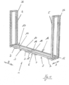
- Fig. 1 shows a schematic perspective view of a stacking aid 1 according to the invention, which, when used as intended, serves to hold a plurality of AGM batteries, which are not shown in detail in the figures for the sake of clarity.
- the stacking aid 1 has a U-shaped base body 2. This in turn has a support element 3 and two cheeks 4 and 5, the cheeks 4 and 5 being arranged on one end and the other end of the support element 3 on the support element 3.
- the support element 3 accommodates a plurality of AGM batteries arranged in rows one above the other. Both the support element 3 and the first side walls of the housings of the AGM batteries are aligned horizontally, so that the ones received by the housings of the AGM batteries and each aligned parallel to the first side walls of the housings Electrode plates of the AGM batteries are also aligned parallel to the support element 3 and thus running horizontally.
- the cheeks 4 and 5 are designed to serve exclusively as lateral protection for AGM batteries accommodated by the support element 3.
- the cheeks 4 and 5 of the stacking aid 1 do not have a supporting function, but only serve as lateral protection for the AGM batteries accommodated by the stacking aid 1, in particular as protection against unwanted mechanical influences from outside.
- the support element 3 has tubes 10 and 11 which are rectangular in cross section. These are aligned parallel to one another and arranged at a distance from one another in a direction transverse to the longitudinal direction of the pipe. To maintain the distance, a spacer 14 is arranged between the two tubes 10 and 11, with several spacers 14 being provided in the exemplary embodiment shown.
- the support element 3 has two detachably connected support element sections 16 and 17. These are identical to one another and arranged one behind the other in the longitudinal direction 8 of the support element 3.
- the connection between the two support element sections 16 and 17 is designed to be detachable, namely by a plug connection, as will be explained below with reference to Fig. 2 will be described.
- the stacking aid 1 also has insulators 7. These are strip-shaped and serve as feet. They are arranged on the support element 3, specifically on the underside 6 facing away from the cheeks. They are made of plastic, preferably of a soft, elastic plastic material.
- a plurality of insulators 7 are preferably provided, which are arranged one behind the other in the longitudinal direction 8 of the support element 3, leaving a distance between them.
- two insulators 7 are provided for each support element section 16 or 17, so that the support element 3 has a total of four insulators 7.
- the insulators 7 extend over the entire width of the support element 3 in Width direction 9. This closes the insulators 7 with the associated tubes 10 and 11 with respect to the plane of the drawing Fig. 1 flush on both the front and back. This factual connection emerges particularly from the illustration below Fig. 6 .
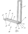
- Base body 2 shown is composed of two L-shaped base bodies 18. Such a base body 18 is in Fig. 2 shown.
- a base body 18 has a support element section 16 or 17 and a cheek 4 or 5 arranged on one side thereof.
- the U-shaped base body 2 is therefore designed in two parts and consists of two base bodies 18, which are U-shaped in the final assembled state trained base body 2 are detachably coupled to one another, as can be seen from a synopsis of the Fig. 1 and 2 results.
- the tubes 10 and 11 of the support element sections 16 and 17 or of the support element 3 formed from the support element sections 16 and 17 are designed to be open at the end and each provide openings 12 and 13, respectively.
- the channels provided by the respective pipes 10 and 11 are accessible via these openings 12 and 13.
- a connecting means 19 is inserted into these channels for the purpose of releasably connecting two base bodies 18, as can be seen in particular from the illustration Fig. 2 results. How Fig. 2 As can be seen in this context, two connecting means 19 are provided, half of which are each accommodated by the associated tube 10 or 11 of the base body 18. In the final assembled state, the connecting means 19 grip with theirs Fig. 2 still free ends into the channels of the adjacent base body 18, that is, into the ones with reference to the plane of the drawing Fig. 1 left base body 18.
- the connecting means 19 are U-shaped in cross section. For the purpose of proper assembly, they must be gripped by their legs and pressed together in a spring-elastic manner. They are oversized with respect to the channels provided by the tubes 10 and 11 so that they can be inserted into the respective channels of the tubes 11 and 12 in a slightly compressed state. Once you relax and return to your starting position Spring back follows a spring-loaded contact of the connecting means 19 on the inner wall of the associated pipes 10 and 11. This creates a positive and non-positive connection that connects the two base bodies 18 to one another permanently and securely, but nevertheless releasably.
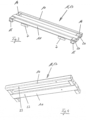
- Fig. 3 shows a schematic perspective view of a support element section 16 or 17.
- spacers 14 are arranged between the two tubes 10 and 11 on one end and on the other end. These ensure a defined and permanently safe spacing of the two pipes 10 and 11.
- Each spacer 14 is also assigned an extension 15, which is on the other end with reference to the plane of the drawing Fig. 1 front tube 11 is arranged on the front tube 11. Both the spacers 14 and the extensions 15 have bores 20 which, in the final assembled state, serve to accommodate fasteners, which are in particular screws 21, as shown Fig. 2 visible.
- the spacers 20 and the extensions 15 serve as anchor points or abutments for the detachable arrangement of the cheeks 4 and 5 on the respective supporting element section 16 and 17, as can be seen in particular from a synopsis of Fig. 1 and 2 results.
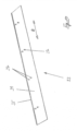
- Each cheek 4 or 5 has shoes 22 on the support element side that correspond to the spacers 14 or the extensions 15. These are also equipped with corresponding holes, so that in the final assembled state the shoe-side holes on the one hand and the holes 20 of the spacers 14 or The extensions 15 are penetrated by the screws 21. This ensures an arrangement of the cheeks 4 and 5 on the support element 3 that is easy to design, but is nevertheless permanently safe and stable.
- a support element section 16 or 17 has holes 23 on its underside 7 facing away from the cheeks. These serve to securely position the insulators 7 already described above.
- Fig. 5 shows an insulator 7 shown separately.
- This has a strip body 24 which is made of a plastic material.
- the strip body 24 is equipped with pins 25 which, when fully assembled, are inserted into associated holes 23 in the Suspension element sections 16 and 17 engage.
- the pins 25 can be designed as threaded pins and/or serve to be bonded to a support element section 16 or 17.
- FIG. 6 Shows a support element section 16 or 17 that is fully equipped with insulators 7 as intended Fig. 6 in a schematic perspective view from below.
- the stacking aid 1 is constructed or expandable according to the modular principle.
- the stacking aid 1 designed in this way according to Fig. 1 can be expanded if necessary, in the longitudinal direction 8, by adding additional base bodies 18 with reference to the plane of the drawing Fig. 1 be added either on the left side and/or right side.
- the tubes 10 and 11 of the support element 3 are each designed to be open at the end, which enables the inclusion of connecting means 19 in the manner already described.
- a base body after Fig. 2 can therefore easily be done with reference to the drawing level Fig. 1 be flanged on the left and/or right side of the stacking aid 1.
- Stacking aid 1 shown can therefore be expanded as desired and can therefore accommodate the desired number of AGM batteries if necessary and thus provide the desired battery capacity.
- a base body 18 flanged to a stacking aid 1 for the purpose of expanding the same can in turn be extended by a further base body 18 by forming a detachable plug connection of the type already described in the same way.
- the entire construction offers the overall advantage that the only one support element 3 provided or the support element sections 16 and 17 forming the support element 3 support the AGM batteries picked up by the stacking aid 1 in the intended use in a force-transmitting manner.
- the cheeks 4 and 5 do not have a supporting function and only serve to provide lateral protection for the AGM batteries held by the stacking aid 1.
- the stacking aid is electrically insulated from the ground at the installation site.
- the insulators 7 also serve as feet, which ensures that the stacking aid 1 remains permanently secure on the surface at the installation site.
- the insulators 7 are strip-shaped, so that they do not enable point-based, but rather area-based force transmission into the ground at the installation site, which increases stability.
- Fig. 7 shows a stacking aid 1 according to the invention according to an alternative embodiment in a schematic perspective view.
- the stacking aid 1 after Fig. 7 is formed from two base bodies 2, which are arranged one above the other in the height direction 26.
- the open sides of the U-shaped base body 2 face each other, so that an overall rectangular, closed design results.
- the support element of the base body 2 arranged at the top in the height direction 26 serves as a roof element 27. Since the two base bodies 2 arranged one above the other in the height direction 26 are identical, the support element of the upper base body 2 serving as a roof element 27 is also designed identically to the support element 3 of the lower base body 2 and has two interconnected roof element sections 28 and 29, which are identical to the support element sections 16 and 17.
- the roof element 27 does not serve to hold AGM batteries, but rather as a closing element, so that an overall closed, therefore rectangular stacking aid 1 is provided.
- the roof element 27 also serves to be able to accommodate a wall fastening 30 if necessary.
- angle elements can be provided, for example, which are arranged on the one hand on the stacking aid 1 and on the other hand on a wall at the installation site, for example a housing wall.
- the connection of such angle elements to one arranged at the top in the height direction 26 Roof element 27 has the particular advantage of effectively counteracting a possible tipping over movement of the stacking aid 1.
- corresponding angle elements are therefore provided as wall fastenings 30 for connecting the roof element 27 to a building wall.
- the support element of the base body 2, which is arranged at the top in the height direction 26, is used as a roof element 27 and is not used to accommodate AGM batteries, the use of a roof element 27 which is identical to the lower support element 3 is preferred, for reasons of simplified handling, in particular with regard to Storage and assembly or disassembly.
- the stacking aid 1 after Fig. 7 is formed in a simple manner in that two base bodies 2 according to the embodiment Fig. 1 be arranged one above the other in the height direction 26.
- the storage capacity of a stacking aid 1 can be doubled by having two base bodies 2 in the design Fig. 1 be arranged one above the other.
- plug-in means are used, for example in the form of tubes or open, U-shaped profiles, which are each inserted into the tubes forming the cheeks 4 and 5.
- a plug connection is used, as already explained above with reference to the support element sections 16 and 17.
- a base body 2 can be used as a stacking aid 1, as shown in Fig. 1 is shown.
- This base body 2 can be made with reference to the plane of the drawing Fig. 1 be supplemented on the left and/or right side, namely by a base body 18, as shown in Fig. 2 is shown.
- it is permitted to arrange two base bodies 2 one above the other in the height direction 26, which alternative embodiment in Fig. 7 is shown.
- a base body 2 arranged at the top can also be supplemented on the left and/or right side by a base body 18, provided of course that the base body 2 lower in the height direction 26 is correspondingly supplemented by base body 18.
- the base body 2 on the one hand and the additional base body 18 on the other hand come to lie one above the other in the height direction 26.
- connection of both the support element sections 16 and 17 and the roof element sections 28 and 29 takes place by means of the plug-in system already described above.
- base bodies 2 or base bodies 18 arranged one above the other are connected to one another, so that an overall simple and tool-free construction of the stacking aid 1 is guaranteed, regardless of the desired installation variant.
- Fig. 8 shows a detailed view of the angle elements serving as wall fastening 30, which are arranged on the roof element 27 in the exemplary embodiment shown.
- Such wall fastenings 30 can of course also be arranged on the cheeks 4 and 5 of both the upper and lower base body 2.
- Fig. 9 finally shows a stacking aid 1 equipped with AGM batteries 32 Fig. 7 .
- the AGM batteries 32 are each aligned so that their first side walls are aligned horizontally, so that the electrode plates provided by the AGM batteries 32 are aligned parallel to the support element 3 of the lower base body 2.
- floor fastenings 31 can be provided as a further option. These floor fastenings 31 can also be angular, and it is preferred to arrange them on the cheeks 4 and 5 of the base body 2 of the stacking aid 1, which is lower in the height direction 26, on the one hand, and on the floor at the installation site, on the other hand. Such a floor fastening 31 serves in particular to ensure a secure stand of the stacking aid 1 even in the event that larger mechanical forces act on the stacking aid 1 from the outside, for example in the event of an earthquake or a collision of a vehicle with the stacking aid 1.
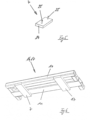
- the Figures 10 and 11 each show a positioning aid 33 according to the invention in a perspective view.
- the positioning aids 33 are according to the Figures 10 and 11 different sizes in the longitudinal direction.
- the size of the positioning aid 33 shown is adapted to a support element 3, which is composed of two support element sections 16 and 17.
- the positioning aid 33 follows Figure 11 is in terms of its longitudinal extent in the longitudinal direction 8 geometric design of a support element section 16 or 17 adapted.
- the positioning aid 33 follows Fig. 10 comes with a U-shaped base body Figure 1 in use.
- the positioning aid 33 serves Figure 11 in the case of extension of the stacking aid 1 for use together with an L-shaped base body 18 Figure 2 .
- the positioning aid 33 has a plate 34, preferably made of plastic. This is equipped with a longitudinal edge 35, which is angled to the plane of the plate 34. This edge 35 serves to securely position the positioning aid 33 within the stacking aid 1.
- the stacking aid 1 has extensions 36, as shown Fig. 1 visible. These extensions 36 are formed on the cheek side and have the shape of webs running in the longitudinal direction of the cheeks 4 and 5. When used as intended, the extensions 36 are aligned vertically, as in Figure 1 shown.
- the positioning aid 33 When the positioning aid 33 is accommodated as intended in the stacking aid 1, the positioning aid 33 lies behind with respect to the plane of the drawing Figure 1 rear edge 35 on the extensions 36 of the cheeks 4 and 5. In this position, the positioning aid 33 is precisely aligned with the stacking aid 1 in relation to the stacking aid 1.
- the edge 35 of the positioning aid 33 also serves for the precise positioning of AGM batteries on the positioning aid 33.
- AGM batteries are placed lying on the positioning aid 33 in such a way that their respective housing base rests on the edge 35.
- the positioning aid 33 therefore serves to align the AGM batteries picked up by the positioning aid 33 in relation to one another, as well as to align the total row of AGM batteries picked up by a positioning aid 33 in relation to the stacking aid 1.
- the positioning aid 33 has spacers 37. These are designed as wooden dowels and inserted into corresponding holes in the plate 34 of the positioning aid 33. As an alternative to designing spacers 37 in the form of wooden dowels, strips can also be provided, in particular plastic strips, which are either integral with the plate 30 of the positioning aid 33 are formed or are glued to the plate 30 of the positioning aid 33.
Landscapes
- Chemical & Material Sciences (AREA)
- Chemical Kinetics & Catalysis (AREA)
- Electrochemistry (AREA)
- General Chemical & Material Sciences (AREA)
- Battery Mounting, Suspending (AREA)
- Sealing Battery Cases Or Jackets (AREA)
Applications Claiming Priority (2)
| Application Number | Priority Date | Filing Date | Title |
|---|---|---|---|
| DE102022123511.4A DE102022123511A1 (de) | 2022-09-14 | 2022-09-14 | System bestehend aus einer Stapelhilfe und einer Mehrzahl von AGM-Batterien |
| DE102022123509.2A DE102022123509A1 (de) | 2022-09-14 | 2022-09-14 | System bestehend aus einer Stapelhilfe und einer Mehrzahl von AGM-Batterien |
Publications (3)
| Publication Number | Publication Date |
|---|---|
| EP4340109A2 true EP4340109A2 (fr) | 2024-03-20 |
| EP4340109A3 EP4340109A3 (fr) | 2024-06-26 |
| EP4340109B1 EP4340109B1 (fr) | 2025-10-01 |
Family
ID=89898830
Family Applications (1)
| Application Number | Title | Priority Date | Filing Date |
|---|---|---|---|
| EP23193772.3A Active EP4340109B1 (fr) | 2022-09-14 | 2023-08-28 | Système comprenant un auxiliaire d'empilage et une pluralité de batteries agm |
Country Status (1)
| Country | Link |
|---|---|
| EP (1) | EP4340109B1 (fr) |
Citations (7)
| Publication number | Priority date | Publication date | Assignee | Title |
|---|---|---|---|---|
| US6162559A (en) | 1998-09-21 | 2000-12-19 | Douglas Battery Manufacturing Company | Compressed battery system for motive power applications |
| EP0922308B1 (fr) | 1997-06-02 | 2001-03-07 | GNB Technologies, Inc. | Ensemble modulaire de plateaux porte-accumulateurs au plomb |
| US20020155346A1 (en) | 1992-02-10 | 2002-10-24 | C&D Charter Holdings, Inc. | Recombinant lead-acid cell and long life battery |
| US20020192543A1 (en) | 1998-11-17 | 2002-12-19 | C&D Charter Holdings, Inc. | Selectable capacity fixed footprint lead-acid battery racking system with horizontal plates |
| US6641951B1 (en) | 1998-09-21 | 2003-11-04 | Douglas Battery Manufacturing Company | Battery cell tray assembly and sytem |
| EP3396733A1 (fr) | 2017-04-25 | 2018-10-31 | HOPPECKE Batterien GmbH & Co. KG. | Système constitué d'un dispositif de réception et accumulateurs d'énergie à disposer dans un dispositif de réception, dispositif de réception et supports de réception d'accumulateurs d'énergie |
| DE202019105570U1 (de) | 2019-10-09 | 2019-10-28 | Hoppecke Batterien Gmbh & Co. Kg | Batterieschrank, Schranksystem und System |
Family Cites Families (1)
| Publication number | Priority date | Publication date | Assignee | Title |
|---|---|---|---|---|
| US12113228B2 (en) * | 2021-02-05 | 2024-10-08 | Caterpillar Inc. | Transportable structure for securing energy storage device racks |
-
2023
- 2023-08-28 EP EP23193772.3A patent/EP4340109B1/fr active Active
Patent Citations (7)
| Publication number | Priority date | Publication date | Assignee | Title |
|---|---|---|---|---|
| US20020155346A1 (en) | 1992-02-10 | 2002-10-24 | C&D Charter Holdings, Inc. | Recombinant lead-acid cell and long life battery |
| EP0922308B1 (fr) | 1997-06-02 | 2001-03-07 | GNB Technologies, Inc. | Ensemble modulaire de plateaux porte-accumulateurs au plomb |
| US6162559A (en) | 1998-09-21 | 2000-12-19 | Douglas Battery Manufacturing Company | Compressed battery system for motive power applications |
| US6641951B1 (en) | 1998-09-21 | 2003-11-04 | Douglas Battery Manufacturing Company | Battery cell tray assembly and sytem |
| US20020192543A1 (en) | 1998-11-17 | 2002-12-19 | C&D Charter Holdings, Inc. | Selectable capacity fixed footprint lead-acid battery racking system with horizontal plates |
| EP3396733A1 (fr) | 2017-04-25 | 2018-10-31 | HOPPECKE Batterien GmbH & Co. KG. | Système constitué d'un dispositif de réception et accumulateurs d'énergie à disposer dans un dispositif de réception, dispositif de réception et supports de réception d'accumulateurs d'énergie |
| DE202019105570U1 (de) | 2019-10-09 | 2019-10-28 | Hoppecke Batterien Gmbh & Co. Kg | Batterieschrank, Schranksystem und System |
Also Published As
| Publication number | Publication date |
|---|---|
| EP4340109A3 (fr) | 2024-06-26 |
| EP4340109B1 (fr) | 2025-10-01 |
Similar Documents
| Publication | Publication Date | Title |
|---|---|---|
| EP3396733B1 (fr) | Système constitué d'un dispositif de réception et accumulateurs d'énergie à disposer dans un dispositif de réception, dispositif de réception et supports de réception d'accumulateurs d'énergie | |
| DE202019105570U1 (de) | Batterieschrank, Schranksystem und System | |
| EP3082509B1 (fr) | Élément de paroi de tiroir avec élément de remplissage pour une paroi de tiroir et meuble | |
| DE102022118386A1 (de) | System bestehend aus einer Stapelhilfe und einer Mehrzahl von AGM-Batterien | |
| DE102015105588A1 (de) | Tischgestell für einen Tisch | |
| EP3657984A1 (fr) | Unité de module d'étagère présentant des plaques perforées de paroi latérale et une structure de liaison | |
| DE102018123691B4 (de) | Gehäuse | |
| DE102011013160A1 (de) | Sockel oder Anbaurahmen für einen Schaltschrank oder ein Rack | |
| EP4340109B1 (fr) | Système comprenant un auxiliaire d'empilage et une pluralité de batteries agm | |
| EP4340110B1 (fr) | Système comprenant un auxiliaire d'empilage et une pluralité de batteries agm | |
| DE102012016797B4 (de) | Dachunterbau in Zickzackform | |
| EP4340104A1 (fr) | Système comprenant un auxiliaire d'empilage et une pluralité de batteries agm | |
| DE102022123509A1 (de) | System bestehend aus einer Stapelhilfe und einer Mehrzahl von AGM-Batterien | |
| DE102022123512A1 (de) | Batterie, insbesondere AGM-Batterie sowie System bestehend aus einer Stapelhilfe und einer Mehrzahl von AGM-Batterien | |
| DE102010016107B4 (de) | Tragbares Bühnenpodestelement | |
| DE102018107020A1 (de) | Haltesystem für eine Kabeltrasse | |
| WO2025002565A1 (fr) | Système doté d'un dispositif d'aide à l'empilement et d'une pluralité de batteries | |
| DE202005007319U1 (de) | Mobiler modularer Atriumbau | |
| DE202024103476U1 (de) | Energiespeicher, insbesondere Lithium-Eisenphosphat-Energiespeicher, mit einem Kompressionsgehäuse | |
| EP0283433B1 (fr) | Agencement de lits de secours | |
| DE102016103149B4 (de) | Container-Aufbewahrungssystem | |
| DE102012011419B4 (de) | "Akkublock aus Akkuflachzellen" | |
| EP2707659A1 (fr) | Entretoise pour pile de modules solaires et pile de modules solaires | |
| EP3623632A2 (fr) | Système de cadre modulaire pour pompes à vide | |
| DE112016006925T5 (de) | Stützstruktur und System |
Legal Events
| Date | Code | Title | Description |
|---|---|---|---|
| PUAI | Public reference made under article 153(3) epc to a published international application that has entered the european phase |
Free format text: ORIGINAL CODE: 0009012 |
|
| STAA | Information on the status of an ep patent application or granted ep patent |
Free format text: STATUS: THE APPLICATION HAS BEEN PUBLISHED |
|
| AK | Designated contracting states |
Kind code of ref document: A2 Designated state(s): AL AT BE BG CH CY CZ DE DK EE ES FI FR GB GR HR HU IE IS IT LI LT LU LV MC ME MK MT NL NO PL PT RO RS SE SI SK SM TR |
|
| RIC1 | Information provided on ipc code assigned before grant |
Ipc: H01M 50/291 20210101ALI20240227BHEP Ipc: H01M 50/264 20210101ALI20240227BHEP Ipc: H01M 50/209 20210101AFI20240227BHEP |
|
| P01 | Opt-out of the competence of the unified patent court (upc) registered |
Effective date: 20240320 |
|
| PUAL | Search report despatched |
Free format text: ORIGINAL CODE: 0009013 |
|
| AK | Designated contracting states |
Kind code of ref document: A3 Designated state(s): AL AT BE BG CH CY CZ DE DK EE ES FI FR GB GR HR HU IE IS IT LI LT LU LV MC ME MK MT NL NO PL PT RO RS SE SI SK SM TR |
|
| RIC1 | Information provided on ipc code assigned before grant |
Ipc: H01M 50/291 20210101ALI20240522BHEP Ipc: H01M 50/264 20210101ALI20240522BHEP Ipc: H01M 50/209 20210101AFI20240522BHEP |
|
| STAA | Information on the status of an ep patent application or granted ep patent |
Free format text: STATUS: REQUEST FOR EXAMINATION WAS MADE |
|
| 17P | Request for examination filed |
Effective date: 20240829 |
|
| RBV | Designated contracting states (corrected) |
Designated state(s): AL AT BE BG CH CY CZ DE DK EE ES FI FR GB GR HR HU IE IS IT LI LT LU LV MC ME MK MT NL NO PL PT RO RS SE SI SK SM TR |
|
| STAA | Information on the status of an ep patent application or granted ep patent |
Free format text: STATUS: EXAMINATION IS IN PROGRESS |
|
| 17Q | First examination report despatched |
Effective date: 20241220 |
|
| GRAP | Despatch of communication of intention to grant a patent |
Free format text: ORIGINAL CODE: EPIDOSNIGR1 |
|
| STAA | Information on the status of an ep patent application or granted ep patent |
Free format text: STATUS: GRANT OF PATENT IS INTENDED |
|
| INTG | Intention to grant announced |
Effective date: 20250513 |
|
| GRAS | Grant fee paid |
Free format text: ORIGINAL CODE: EPIDOSNIGR3 |
|
| GRAA | (expected) grant |
Free format text: ORIGINAL CODE: 0009210 |
|
| STAA | Information on the status of an ep patent application or granted ep patent |
Free format text: STATUS: THE PATENT HAS BEEN GRANTED |
|
| AK | Designated contracting states |
Kind code of ref document: B1 Designated state(s): AL AT BE BG CH CY CZ DE DK EE ES FI FR GB GR HR HU IE IS IT LI LT LU LV MC ME MK MT NL NO PL PT RO RS SE SI SK SM TR |
|
| REG | Reference to a national code |
Ref country code: GB Ref legal event code: FG4D Free format text: NOT ENGLISH Ref country code: CH Ref legal event code: F10 Free format text: ST27 STATUS EVENT CODE: U-0-0-F10-F00 (AS PROVIDED BY THE NATIONAL OFFICE) Effective date: 20251001 |
|
| REG | Reference to a national code |
Ref country code: DE Ref legal event code: R096 Ref document number: 502023001889 Country of ref document: DE |
|
| REG | Reference to a national code |
Ref country code: IE Ref legal event code: FG4D Free format text: LANGUAGE OF EP DOCUMENT: GERMAN |
|
| REG | Reference to a national code |
Ref country code: NL Ref legal event code: MP Effective date: 20251001 |
|
| PG25 | Lapsed in a contracting state [announced via postgrant information from national office to epo] |
Ref country code: NL Free format text: LAPSE BECAUSE OF FAILURE TO SUBMIT A TRANSLATION OF THE DESCRIPTION OR TO PAY THE FEE WITHIN THE PRESCRIBED TIME-LIMIT Effective date: 20251001 |
|
| PG25 | Lapsed in a contracting state [announced via postgrant information from national office to epo] |
Ref country code: ES Free format text: LAPSE BECAUSE OF FAILURE TO SUBMIT A TRANSLATION OF THE DESCRIPTION OR TO PAY THE FEE WITHIN THE PRESCRIBED TIME-LIMIT Effective date: 20251001 |
|
| REG | Reference to a national code |
Ref country code: LT Ref legal event code: MG9D |
|
| PG25 | Lapsed in a contracting state [announced via postgrant information from national office to epo] |
Ref country code: NO Free format text: LAPSE BECAUSE OF FAILURE TO SUBMIT A TRANSLATION OF THE DESCRIPTION OR TO PAY THE FEE WITHIN THE PRESCRIBED TIME-LIMIT Effective date: 20260101 |
|
| PG25 | Lapsed in a contracting state [announced via postgrant information from national office to epo] |
Ref country code: FI Free format text: LAPSE BECAUSE OF FAILURE TO SUBMIT A TRANSLATION OF THE DESCRIPTION OR TO PAY THE FEE WITHIN THE PRESCRIBED TIME-LIMIT Effective date: 20251001 Ref country code: HR Free format text: LAPSE BECAUSE OF FAILURE TO SUBMIT A TRANSLATION OF THE DESCRIPTION OR TO PAY THE FEE WITHIN THE PRESCRIBED TIME-LIMIT Effective date: 20251001 |
|
| PG25 | Lapsed in a contracting state [announced via postgrant information from national office to epo] |
Ref country code: RS Free format text: LAPSE BECAUSE OF FAILURE TO SUBMIT A TRANSLATION OF THE DESCRIPTION OR TO PAY THE FEE WITHIN THE PRESCRIBED TIME-LIMIT Effective date: 20260101 |
|
| PG25 | Lapsed in a contracting state [announced via postgrant information from national office to epo] |
Ref country code: IS Free format text: LAPSE BECAUSE OF FAILURE TO SUBMIT A TRANSLATION OF THE DESCRIPTION OR TO PAY THE FEE WITHIN THE PRESCRIBED TIME-LIMIT Effective date: 20260201 |
|
| PG25 | Lapsed in a contracting state [announced via postgrant information from national office to epo] |
Ref country code: CZ Free format text: LAPSE BECAUSE OF FAILURE TO SUBMIT A TRANSLATION OF THE DESCRIPTION OR TO PAY THE FEE WITHIN THE PRESCRIBED TIME-LIMIT Effective date: 20251001 Ref country code: PT Free format text: LAPSE BECAUSE OF FAILURE TO SUBMIT A TRANSLATION OF THE DESCRIPTION OR TO PAY THE FEE WITHIN THE PRESCRIBED TIME-LIMIT Effective date: 20260202 |
|
| PG25 | Lapsed in a contracting state [announced via postgrant information from national office to epo] |
Ref country code: PL Free format text: LAPSE BECAUSE OF FAILURE TO SUBMIT A TRANSLATION OF THE DESCRIPTION OR TO PAY THE FEE WITHIN THE PRESCRIBED TIME-LIMIT Effective date: 20251001 |
|
| PG25 | Lapsed in a contracting state [announced via postgrant information from national office to epo] |
Ref country code: LV Free format text: LAPSE BECAUSE OF FAILURE TO SUBMIT A TRANSLATION OF THE DESCRIPTION OR TO PAY THE FEE WITHIN THE PRESCRIBED TIME-LIMIT Effective date: 20251001 |