EP4340201A1 - Verfahren und system zur steuerung eines schaltnetzteils - Google Patents
Verfahren und system zur steuerung eines schaltnetzteils Download PDFInfo
- Publication number
- EP4340201A1 EP4340201A1 EP23196725.8A EP23196725A EP4340201A1 EP 4340201 A1 EP4340201 A1 EP 4340201A1 EP 23196725 A EP23196725 A EP 23196725A EP 4340201 A1 EP4340201 A1 EP 4340201A1
- Authority
- EP
- European Patent Office
- Prior art keywords
- voltage
- electrolytic capacitor
- output power
- reference voltage
- vref
- Prior art date
- Legal status (The legal status is an assumption and is not a legal conclusion. Google has not performed a legal analysis and makes no representation as to the accuracy of the status listed.)
- Pending
Links
Images

Classifications
-
- H—ELECTRICITY
- H02—GENERATION; CONVERSION OR DISTRIBUTION OF ELECTRIC POWER
- H02M—APPARATUS FOR CONVERSION BETWEEN AC AND AC, BETWEEN AC AND DC, OR BETWEEN DC AND DC, AND FOR USE WITH MAINS OR SIMILAR POWER SUPPLY SYSTEMS; CONVERSION OF DC OR AC INPUT POWER INTO SURGE OUTPUT POWER; CONTROL OR REGULATION THEREOF
- H02M1/00—Details of apparatus for conversion
- H02M1/14—Arrangements for reducing ripples from DC input or output
- H02M1/143—Arrangements for reducing ripples from DC input or output using compensating arrangements
-
- H—ELECTRICITY
- H02—GENERATION; CONVERSION OR DISTRIBUTION OF ELECTRIC POWER
- H02M—APPARATUS FOR CONVERSION BETWEEN AC AND AC, BETWEEN AC AND DC, OR BETWEEN DC AND DC, AND FOR USE WITH MAINS OR SIMILAR POWER SUPPLY SYSTEMS; CONVERSION OF DC OR AC INPUT POWER INTO SURGE OUTPUT POWER; CONTROL OR REGULATION THEREOF
- H02M1/00—Details of apparatus for conversion
- H02M1/42—Circuits or arrangements for compensating for or adjusting power factor in converters or inverters
- H02M1/4208—Arrangements for improving power factor of AC input
-
- H—ELECTRICITY
- H02—GENERATION; CONVERSION OR DISTRIBUTION OF ELECTRIC POWER
- H02M—APPARATUS FOR CONVERSION BETWEEN AC AND AC, BETWEEN AC AND DC, OR BETWEEN DC AND DC, AND FOR USE WITH MAINS OR SIMILAR POWER SUPPLY SYSTEMS; CONVERSION OF DC OR AC INPUT POWER INTO SURGE OUTPUT POWER; CONTROL OR REGULATION THEREOF
- H02M1/00—Details of apparatus for conversion
- H02M1/0003—Details of control, feedback or regulation circuits
- H02M1/0025—Arrangements for modifying reference values, feedback values or error values in the control loop of a converter
-
- H—ELECTRICITY
- H02—GENERATION; CONVERSION OR DISTRIBUTION OF ELECTRIC POWER
- H02M—APPARATUS FOR CONVERSION BETWEEN AC AND AC, BETWEEN AC AND DC, OR BETWEEN DC AND DC, AND FOR USE WITH MAINS OR SIMILAR POWER SUPPLY SYSTEMS; CONVERSION OF DC OR AC INPUT POWER INTO SURGE OUTPUT POWER; CONTROL OR REGULATION THEREOF
- H02M1/00—Details of apparatus for conversion
- H02M1/14—Arrangements for reducing ripples from DC input or output
-
- H—ELECTRICITY
- H02—GENERATION; CONVERSION OR DISTRIBUTION OF ELECTRIC POWER
- H02M—APPARATUS FOR CONVERSION BETWEEN AC AND AC, BETWEEN AC AND DC, OR BETWEEN DC AND DC, AND FOR USE WITH MAINS OR SIMILAR POWER SUPPLY SYSTEMS; CONVERSION OF DC OR AC INPUT POWER INTO SURGE OUTPUT POWER; CONTROL OR REGULATION THEREOF
- H02M1/00—Details of apparatus for conversion
- H02M1/32—Means for protecting converters other than automatic disconnection
-
- H—ELECTRICITY
- H02—GENERATION; CONVERSION OR DISTRIBUTION OF ELECTRIC POWER
- H02M—APPARATUS FOR CONVERSION BETWEEN AC AND AC, BETWEEN AC AND DC, OR BETWEEN DC AND DC, AND FOR USE WITH MAINS OR SIMILAR POWER SUPPLY SYSTEMS; CONVERSION OF DC OR AC INPUT POWER INTO SURGE OUTPUT POWER; CONTROL OR REGULATION THEREOF
- H02M1/00—Details of apparatus for conversion
- H02M1/36—Means for starting or stopping converters
-
- H—ELECTRICITY
- H02—GENERATION; CONVERSION OR DISTRIBUTION OF ELECTRIC POWER
- H02M—APPARATUS FOR CONVERSION BETWEEN AC AND AC, BETWEEN AC AND DC, OR BETWEEN DC AND DC, AND FOR USE WITH MAINS OR SIMILAR POWER SUPPLY SYSTEMS; CONVERSION OF DC OR AC INPUT POWER INTO SURGE OUTPUT POWER; CONTROL OR REGULATION THEREOF
- H02M7/00—Conversion of AC power input into DC power output; Conversion of DC power input into AC power output
- H02M7/02—Conversion of AC power input into DC power output without possibility of reversal
- H02M7/04—Conversion of AC power input into DC power output without possibility of reversal by static converters
-
- H—ELECTRICITY
- H02—GENERATION; CONVERSION OR DISTRIBUTION OF ELECTRIC POWER
- H02M—APPARATUS FOR CONVERSION BETWEEN AC AND AC, BETWEEN AC AND DC, OR BETWEEN DC AND DC, AND FOR USE WITH MAINS OR SIMILAR POWER SUPPLY SYSTEMS; CONVERSION OF DC OR AC INPUT POWER INTO SURGE OUTPUT POWER; CONTROL OR REGULATION THEREOF
- H02M3/00—Conversion of DC power input into DC power output
- H02M3/22—Conversion of DC power input into DC power output with intermediate conversion into AC
- H02M3/24—Conversion of DC power input into DC power output with intermediate conversion into AC by static converters
- H02M3/28—Conversion of DC power input into DC power output with intermediate conversion into AC by static converters using discharge tubes with control electrode or semiconductor devices with control electrode to produce the intermediate AC
- H02M3/325—Conversion of DC power input into DC power output with intermediate conversion into AC by static converters using discharge tubes with control electrode or semiconductor devices with control electrode to produce the intermediate AC using devices of a triode or a transistor type requiring continuous application of a control signal
- H02M3/335—Conversion of DC power input into DC power output with intermediate conversion into AC by static converters using discharge tubes with control electrode or semiconductor devices with control electrode to produce the intermediate AC using devices of a triode or a transistor type requiring continuous application of a control signal using semiconductor devices only
- H02M3/337—Conversion of DC power input into DC power output with intermediate conversion into AC by static converters using discharge tubes with control electrode or semiconductor devices with control electrode to produce the intermediate AC using devices of a triode or a transistor type requiring continuous application of a control signal using semiconductor devices only in push-pull configuration
- H02M3/3372—Conversion of DC power input into DC power output with intermediate conversion into AC by static converters using discharge tubes with control electrode or semiconductor devices with control electrode to produce the intermediate AC using devices of a triode or a transistor type requiring continuous application of a control signal using semiconductor devices only in push-pull configuration of the parallel type
- H02M3/3374—Conversion of DC power input into DC power output with intermediate conversion into AC by static converters using discharge tubes with control electrode or semiconductor devices with control electrode to produce the intermediate AC using devices of a triode or a transistor type requiring continuous application of a control signal using semiconductor devices only in push-pull configuration of the parallel type with preregulator, e.g. current injected push-pull
-
- Y—GENERAL TAGGING OF NEW TECHNOLOGICAL DEVELOPMENTS; GENERAL TAGGING OF CROSS-SECTIONAL TECHNOLOGIES SPANNING OVER SEVERAL SECTIONS OF THE IPC; TECHNICAL SUBJECTS COVERED BY FORMER USPC CROSS-REFERENCE ART COLLECTIONS [XRACs] AND DIGESTS
- Y02—TECHNOLOGIES OR APPLICATIONS FOR MITIGATION OR ADAPTATION AGAINST CLIMATE CHANGE
- Y02B—CLIMATE CHANGE MITIGATION TECHNOLOGIES RELATED TO BUILDINGS, e.g. HOUSING, HOUSE APPLIANCES OR RELATED END-USER APPLICATIONS
- Y02B70/00—Technologies for an efficient end-user side electric power management and consumption
- Y02B70/10—Technologies improving the efficiency by using switched-mode power supplies [SMPS], i.e. efficient power electronics conversion e.g. power factor correction or reduction of losses in power supplies or efficient standby modes
Definitions
- the present disclosure relates to a technical field of power supply control, in particular to a method and a system for controlling a switching power supply.
- Electrolytic capacitor is widely used in switching power supply, such as output capacitor of PFC converter and input capacitor of grid connected inverter.
- the low temperature characteristics of the electrolytic capacitor are poor.
- ESR equivalent series resistance
- high load power will cause too high ripple voltage of the electrolytic capacitor, which may easily trigger the protection, and even lead to the damage of the electrolytic capacitor. Therefore, under low temperature conditions, the electrolytic capacitor is usually preheated, that is, the load power of the switching power supply is set to operate at a low value for a period of time, so that the core temperature of the electrolytic capacitor gradually rises. After its capacitance and ESR are restored to a reasonable range, the output power is gradually increased until full load.
- the output power is small in the warm-up stage, needing to wait for a long time;
- the identification of the ambient temperature through the controller to predict the temperature of the electrolytic capacitor requires a temperature sensor, whose accuracy requirements increase the complexity of the device;
- the purpose of the present disclosure is to provide a method and a system for controlling a switching power supply to regulate the output power according to the capacitance of the electrolytic capacitor itself and equivalent series resistance (ESR), so that the ripple voltage of the electrolytic capacitor is always kept within the safety limit by adjusting the output power of the switching power supply, thus the warm-up time is reduced, and the safe operation of the switching power supply is achieved.
- ESR equivalent series resistance
- the present disclosure provides a method for controlling a switching power supply, the switching power supply comprising a power factor correction circuit which comprises at least one electrolytic capacitor, and the method comprises the following steps:
- the present disclosure provides a system for controlling a switching power supply, the switching power supply comprising a power factor correction circuit which comprises at least one electrolytic capacitor, and the system comprises:
- the technical solution disclosed in the present disclosure by detecting the ripple voltage of the electrolytic capacitor of the switching power supply and regulating the output power of the switching power supply based on the ripple voltage of the electrolytic capacitor, keeps the ripple voltage of the electrolytic capacitor always within the safety limit, ensuring the safe and reliable operation of the switching power supply. Besides, by regulating the output power of the switching power supply, the present solution reduces the warm-up time of the electrolytic capacitor and improves the control efficiency and control precision of switching power supply by reducing the warm-up time of the electrolytic capacitor.
- references in the present description to "one embodiment”, “embodiment”, “example embodiment”, etc. mean that the described embodiment may include specific features, structures or characteristics, but not every embodiment must contain these specific features, structures or characteristics. Furthermore, such expression does not refer to the same embodiment. Further, describing specific features, structures or characteristics in combination with embodiments has shown that it is within the knowledge of those skilled in the art to combine such features, structures or characteristics with other embodiments, no matter whether there is a clear description or not.
- connection here includes any direct and indirect means of connection. Indirect electric connection means comprises connection by means of other devices.
- the principle of the present disclosure is that, by detecting a ripple voltage of electrolytic capacitor of the PFC stage in the switching power supply and regulating the output power of the switching power supply based on the ripple voltage of the electrolytic capacitor to control the peak value and valley value of the ripple voltage of the electrolytic capacitor are always within the safety limit, thus reducing the warm-up time of the electrolytic capacitor during the start process of the switching power supply, while ensuring the safe and reliable operation.
- a single-phase AC/DC switching power supply is used as an example for the description in the following embodiment, but not as a limitation upon the present disclosure.
- the present disclosure may also be used for three-phase AC/DC switching power supply, single-phase or three-phase DC/AC switching power supply, etc.
- Fig. 1 is an equivalent circuit diagram of the AC/DC switching power supply according to an embodiment of the present disclosure.
- a single-phase AC/DC switching power supply may be composed of two-stage converters.
- the first stage may be AC/DC converter 1, which realizes the PFC function, that is, PFC converter, and the second stage may be DC/DC converter 2.
- the capacitor connected to the output bus of the PFC comprises at least one electrolytic capacitor Cbus.
- the capacitor may comprise multiple electrolytic capacitors, the multiple electrolytic capacitors may be connected in parallel.
- multiple electrolytic capacitors may be connected in series to form multiple groups of electrolytic capacitors, then groups may be connected in parallel.
- the connection mode of the electrolytic capacitors in the present disclosure is not subject to such limitation.
- the electrolytic capacitor may be equivalent to a combination of capacitor and ESR (equivalent series resistor) under the low-frequency (the frequency is grid frequency or double grid frequency), a ripple voltage Vpp will be generated on ESR due to a ripple current flowing through the ESR.
- the electrolytic capacitor may be equivalent to a combination of an ideal capacitor and a parasitic resistance in series under low-frequency, and the parasitic resistance is the equivalent series resistance ESR.
- the ripple current flows through the ideal capacitor, and its charging and discharging processes will produce the ripple voltage.
- the ripple voltage is 90 ° lagged behind of the ripple current, and the larger the ripple current is, the larger the ripple voltage is.
- ripple current flowing through the parasitic resistance will also produce ripple voltage.
- the ripple voltage and ripple current have the same phase, and the larger the ripple current is, the larger the ripple voltage is. Therefore, the ripple voltage of electrolytic capacitor is the vector sum of ideal capacitor ripple voltage and parasitic resistance ripple voltage, thus the larger the ripple current is, the larger the ripple voltage of electrolytic capacitor is.
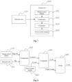
- Fig. 2 is a control schematic diagram of the AC/DC switching power supply according to an embodiment of the present disclosure, as shown in the figure: a reference voltage may be provided, and a compensated output power may be obtained by compensation calculation after detecting the ripple voltage of the electrolytic capacitor and comparing the detected ripple voltage with the reference voltage; an upper limit output power may be provided, and the smaller value between the compensated output power and the upper limit output power may be taken as the reference output power for the switching power supply; the actual output voltage of the switching power supply may be obtained, and the reference output current may be obtained based on the reference output power and the actual output voltage of the switching power supply; the second stage converter of the switching power supply controls the output current of the switching power supply based on the reference output current, and then regulates the output power of the switching power supply and controls the ripple voltage of the electrolytic capacitor of the first stage converter.
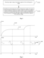
- FIG. 3 shows a flow diagram of a method for controlling the switching power supply according to an embodiment of the present disclosure, wherein the method includes the following steps:
- the reference output power P_ref when the compensated output power is less than the upper limit output power, the reference output power P_ref may be set to be equal to the compensated output power P_error; and when the compensated output power is greater than or equal to the upper limit output power, the reference output power P_ref may be set to be equal to the upper limit output power P_limit.
- an average value of its output voltage may be a constant value. That is, the average voltage Vavg of the electrolytic capacitor may be a constant value.
- the output voltage of the PFC converter (that is, the electrolytic capacitor voltage) may be the superposition of an average value of the electrolytic capacitor voltage and the ripple voltage Vpp of the electrolytic capacitor. Since the output power of the first stage power supply is positively related to the output power of the second stage power supply, the greater the output power of the second stage power supply is, the greater the output power of the first stage power supply is, the greater the output current of the first stage power supply, the greater the ripple current flowing through the electrolytic capacitor is, and the greater the ripple voltage of the electrolytic capacitor is.
- the ripple voltage of the electrolytic capacitor may always be controlled within the range that may ensure the safe operation of the switching power supply. It is preferable that the electrolytic capacitor voltage may be controlled to less than a setting value of an overvoltage protection for the PFC output and greater than a minimum value of input voltage of the switching power supply under normal operation, and the ripple voltage of the electrolytic capacitor is less than a rated ripple voltage.
- the method for controlling the switching power supply also includes controlling the output current of the switching power supply, and for the output current of the switching power supply, the reference output current I_ref may be obtained based on the reference output power of the second stage P_ref of the switching power supply and the real-time sampled output voltage of the switching power supply.
- the second stage converter controls the output current based on the reference output current I_ref, that is, the output power of the first stage converter is controlled through the control of the output power of the second stage converter, and then the ripple voltage of the electrolytic capacitor is controlled.
- the value of the upper limit output power may be a constant value, as shown in Fig. 4 .
- the constant value may be a rated output power of the switching power supply.
- the ripple voltage of the electrolytic capacitor is less than the reference output power during the start-up of the switching power supply, reference output power as the compensated output power keeps increasing, thus the output power may reach the rated output power earlier.
- the upper limit output power may also be a gradually increasing function from an initial power value to a rated output power of the switching power supply. As shown in Fig.
- the reference output power when the compensated output power is greater than the upper limit output power, the reference output power may be controlled equal to the value of the upper limit output power according to the function of the upper limit.
- the output power increases according to the set power growth curve of the upper limit output power function.
- the increment of the output power may be smoother.
- the curve of the function may include a linear increase curve, a stepwise increment curve or a nonlinear increment curve, which is not a limit on the present disclosure.
- the ripple voltage of the electrolytic capacitor may be obtained to compare with the reference voltage in each sampling cycle, and then the compensated output power may be calculated.
- the reference voltage includes a first reference voltage. If the ripple voltage of the electrolytic capacitor is greater than the first reference voltage, the compensated output power may gradually decrease and the ripple voltage of the electrolytic capacitor may be repeatedly obtained in the next sampling cycle. If the ripple voltage of the electrolytic capacitor is less than or equal to the first reference voltage, the compensated output power may gradually increase.
- the reference voltage includes a first reference voltage and a second reference voltage, and the first reference voltage is greater than the second voltage.
- the compensated output power may gradually decrease and the ripple voltage of the electrolytic capacitor may be repeatedly obtained in the next sampling cycle.
- the compensated output power may be controlled to be maintained and the electrolytic capacitor voltage may to be obtained repeatedly in the next sampling cycle; and when the ripple voltage of the electrolytic capacitor is less than the second reference voltage, the compensated output power may gradually increase.
- the electrolytic capacitor voltage of the first stage converter may be equivalent to the superposition of an average value of the electrolytic capacitor voltage and the ripple voltage Vpp of the electrolytic capacitor.
- the ripple voltage of the electrolytic capacitor may also be obtained from the peak to peak value, peak value or valley value of the electrolytic capacitor voltage.
- the peak to peak voltage of the electrolytic capacitor voltage may be used to obtain the ripple voltage of the electrolytic capacitor in each sampling cycle, and perform the compensation calculation for the current compensated output power, which specifically include:
- Fig. 6 is a flow diagram of obtaining the ripple voltage through the peak to peak value of the electrolytic capacitor voltage to perform compensation calculation of the compensated output power according to an embodiment of the present disclosure in a low temperature environment, which is used to further elaborate the above control process.
- the electrolytic capacitor voltage is real time sampled and the peak and peak values of the ripple voltage of the electrolytic capacitor may be obtained in each sampling cycle, which the period of the sampling cycle based upon the grid frequency or twice the grid frequency.
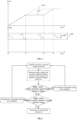
- Fig. 4 is a schematic diagram of control process of obtaining the ripple voltage of the electrolytic capacitor through the peak to peak value of the electrolytic capacitor voltage to perform compensation calculation of the compensated power according to an embodiment of the present disclosure. Referring to Fig.
- the reference voltage includes a first reference voltage Vref_1 and a second reference voltage Vref_2. From the time T0 to T1, the output power of switching power increases according to the compensated output power.
- the compensated output power may be controlled to increase; From the time T1 to T2, as the output power keeps increasing, Vpp keeps increasing under low temperature.
- the compensated output power may be controlled to be maintained, the compensated output power is less than the upper limit output power, and the output power of the switching power supply is maintained.
- the ripple current flowing through the electrolytic capacitor makes its core temperature gradually increase. Accordingly, even if the output power of the switching power supply is maintained, the ripple voltage Vpp of the electrolytic capacitor gradually decreases.
- the ripple voltage Vpp is less than the reference voltage Vpp_ ref (Vref_1 or Vref_2 at T2, the compensated power may be controlled to gradually increase.
- the switching power supply may be controlled to output the upper limit output power.
- Fig. 5 is a schematic diagram of control process of obtaining the ripple voltage of the electrolytic capacitor through the peak to peak value of the electrolytic capacitor voltage to perform compensation calculation of the compensated power in another embodiment of the present disclosure.
- the reference voltage includes a first reference voltage Vref_1 and a second reference voltage Vref_2. From the time T0 to T1, the output power of switching power supply starts to increase.
- the compensated output power may be controlled to increase; from the time T1 to T2, as the output power keeps increasing, the ripple voltage Vpp of the electrolytic capacitor keeps increasing under low temperature.
- the compensated output power may be controlled to be maintained.
- the ripple current flowing through the electrolytic capacitor makes its core temperature gradually increase, and the ripple voltage Vpp of the electrolytic capacitor gradually decreases; at the time T2, the ripple voltage Vpp is less than the Vref at T2, and the compensated power may be controlled to gradually increase; until T3, the compensated power is equal to the upper limit output power, the switching power supply may be controlled to output the upper limit output power.
- the process of output power increment may be more stable.
- the first reference voltage value may be determined according to the rated ripple voltage and the over-voltage protection value of the PFC DC bus.
- the second threshold voltage may be set to be equal to a maximum ripple voltage of the electrolytic capacitor under fully loaded operation at room temperature.
- the first threshold voltage may be the rated ripple voltage.
- the rated ripple voltage is 70V.
- the first threshold voltage may be a smaller one of them, namely 70V.
- the first reference voltage and the second reference voltage may be adjusted according to actual needs and the present disclosure is not limited to that.
- the first reference voltage Vref_1 may be equal to the second reference voltage Vref_2, the power establishment process of switching power supplies are similar to the above embodiments. The difference is that the compensated output power is maintained when the ripple voltage Vpp is equal to the first or the second reference voltage. From the time To to T1, the output power of the switching power supply starts to increase, the ripple voltage Vpp of the electrolytic capacitor may obtained in each sampling cycle. When the ripple voltage Vpp is less than the first reference voltage Vref_1 and its output power is less than the upper limit output power P_ Limit, the compensated output power may be controlled to increase, and the ripple voltage Vpp is repeatedly obtained in the next sampling cycle.
- the compensated output power may be controlled to be decreased, and the ripple voltage Vpp is repeatedly obtained in the next sampling cycle.
- the ripple voltage Vpp is less than the first reference voltage Vref_1
- the compensated output power may be controlled to increase again;
- the compensation power may be controlled to increase till the compensation power equals to the upper limit output power P_ Limit, the output power of the switching power supply may be controlled to be equal to the upper limit output power P_ limit.
- step S120 the peak voltage of electrolytic capacitor voltage may be obtained in each sampling cycle to perform the compensation calculation for the current compensated output power, which specifically include:
- the second threshold voltage is set to be equal to a sum of a half maximum ripple voltage of the electrolytic capacitor under fully loaded operation at room temperature and an average value of the electrolytic capacitor voltage.
- the first threshold voltage may be set to be equal to a sum of half of the rated ripple voltage and an average value of the electrolytic capacitor voltage.
- the first threshold voltage may be set to be equal to the setting value of an overvoltage protection for the switching power supply.
- the first reference voltage and the second reference voltage may be adjusted according to actual needs and the present disclosure is not limited to that.
- a valley voltage of electrolytic capacitor voltage may be obtained in each sampling cycle to perform the compensation calculation for the current compensated output power, which specifically include:
- the first threshold voltage is set to be equal to a difference between an average value of the electrolytic capacitor voltage and half of the maximum ripple voltage of the electrolytic capacitor j under fully loaded operation at room temperature.
- the second threshold voltage may be set to be equal to a difference between the average value of the electrolytic capacitor voltage and half of the rated ripple voltage when the difference between the average value of the electrolytic capacitor voltage and half of the rated ripple voltage is greater than or equal to a setting value of an undervoltage protection of the switching power supply.
- the second threshold voltage may be set to be equal to the setting value of an undervoltage protection of the switching power supply when the difference between the average value of the electrolytic capacitor voltage and half of the rated ripple voltage is less than the setting value of an undervoltage protection of the switching power supply.
- the first reference voltage and the second reference voltage may be adjusted according to actual needs and the present disclosure is not limited to that.
- the first reference voltage and the second reference voltage are set respectively a constant value; or, the first reference voltage may be a first function in which a value of the first reference voltage increases gradually from a first initial value to the first threshold voltage, for example, the gradual increase from 10V to 50V.
- the second reference voltage may be a second function in which a value of the second reference voltage increases gradually from a second initial value to the second threshold voltage, for example, the gradual increase from 0V to 40V.
- the curve of the function may include a linear increase curve, a stepwise increment curve or a nonlinear increment curve, etc.
- the first reference voltage and the second reference voltage may be adjusted according to actual needs and the present disclosure is not limited to that.
- the voltages of each electrolytic capacitor are detected respectively.
- the compensated output power of the switching power supply may be controlled to reduce.
- the compensated output power of the control switching power supply may be maintained.
- the compensated output power of the control switching power supply may be controlled to increase.
- the control mode of the present disclosure does not need to detect the temperature, and is suitable for establishing the power of the switching power supply under various circumstances. Under the conditions of high temperature and normal temperature, the capacitance value of the electrolytic capacitor is large and the ESR is small. During the power establishment process, when the ripple voltage of the electrolytic capacitor is less than the reference voltage, the compensated output power obtained through the compensation calculation of the output power of the switching power supply may be greater than the upper limit output power, thus the upper limit output power determines the output power during the power establishment process, Therefore, this control method will not affect the speed of output power establishment under high temperature and normal temperature conditions.
- the switching power supply outputs the actual output power according to the compensated power.
- the switching power supply using the control method keeps outputting the maximum allowable power based on the current state of the electrolytic capacitor.
- the ripple voltage of the electrolytic capacitor is controlled within a safe range, switching power overvoltage may be avoided during the startup of the switching power supply, and the ripple voltage of the electrolytic capacitor is always lower than the maximum ripple voltage that the device may withstand, so the establishment process of the power of switching power supply may be highly reliable; at the same time, compared with the manner of keeping outputting a relative lower output power, waiting for the capacitance value of the electrolytic capacitor and the ESR to reduce to a reasonable range and then increasing the output power of the switching power supply, outputting the maximum allowable power based on the current state of the electrolytic capacitor may accelerate the power establishment process.
- Fig. 7 is a structural diagram of a system for controlling the switching power supply according to an embodiment of the present disclosure.
- the switching power supply comprises a power factor correction circuit which comprises at least one electrolytic capacitor.
- the controlling system described below and the controlling method described above may be mutually corresponded and referred to. Referring to Fig. 7 , the controlling system comprises:
- the reference output power may be a compensated output power or an upper limit output power, and the compensated output power is to be obtained by comparing the ripple voltage of the electrolytic capacitor with a reference voltage and subjecting to a compensation calculation.
- the reference output power may be set to be equal to the compensated output power.
- the compensated output power is greater than or equal to the upper limit output power
- the reference output power may be set to be equal to the upper limit output power.
- control unit 220 may include:
- the voltage control module 221 may gradually increase the reference voltage value during an operation of the switching power supply, comprising a linear increase, a stepwise increment or a nonlinear increment, or output a maximum reference voltage directly from the initial time.
- the power control module 223 may also gradually increase the upper limit output power value during an operation of the switching power supply, comprising a linear increase, a stepwise increment or a nonlinear increment, or output a maximum upper limit output power directly value from the initial time.
- the compensator 222 may comprise a P regulator, a PI regulator, a PID regulator, a PIR regulator or a nonlinear regulator.
- Fig. 8 is a structural schematic diagram of a system for controlling an AC/DC switching power supply according to an embodiment of the present disclosure.
- the voltage control module 221 may output a reference voltage Vpp_ref.
- the reference voltage Vpp_ref together with the ripple voltage Vpp of the electrolytic capacitor detected by the detection unit 210 may be sent to a compensator 222, and the compensator 222 may output a compensated output power P_error by a compensation calculation according to the reference voltage Vpp_ref and the detected ripple voltage Vpp.
- the compensated output power P_error together with the upper limit output power P_limit outputted by the power control module 223 may be sent to the comparator 224, and the comparator 224 may output a reference output power P_ref with a value equal to the smaller value of the compensated output power P_error and the upper limit output power P_limit.
- the reference value P_ref of the output power and the actual output voltage of the switching power supply may be sent to the divider 225 to obtain the reference value I_ref.
- the second converter of the switching power supply controls the output current of the switching power supply based on the reference output current I_ref, thus regulates the output power of the switching power supply and the ripple voltage of the electrolytic capacitor is controlled within the safety limit to ensure the safe operation of the switching power supply.
- the compensator 222 compares the ripple voltage of the electrolytic capacitor with the reference voltage and outputs the compensated output power after the compensation calculation.
- the reference voltage may be outputted by the voltage control module 221 includes a first reference voltage. If the ripple voltage of the electrolytic capacitor is greater than the first reference voltage, the compensated output power may gradually decrease and the ripple voltage of the electrolytic capacitor may be repeatedly obtained in the next sampling cycle. If the ripple voltage of the electrolytic capacitor is less than or equal to the first reference voltage, the compensated output power may gradually increase.
- the reference voltage outputted by the voltage control module 221 includes a first reference voltage and a second reference voltage, the first reference voltage may be set to be greater than the second voltage.
- the compensated output power may gradually decrease and the ripple voltage of the electrolytic capacitor may be repeatedly obtained in the next sampling cycle.
- the compensated output power may be maintained and the electrolytic capacitor voltage may be obtained repeatedly in the next sampling cycle.
- the compensated output power may gradually increase.
- the electrolytic capacitor voltage on its may be equivalent to the superposition of an average value of the electrolytic capacitor voltage and the ripple voltage Vpp of the electrolytic capacitor. It is preferable that the electrolytic capacitor voltage may be controlled to be less than a setting value of an overvoltage protection for the switching power supply PFC output and greater than a minimum input voltage value under normal operation of the switching power supply, and the ripple voltage of the electrolytic capacitor is less than a rated ripple parameter. In some embodiments, the ripple voltage of the electrolytic capacitor may also be obtained from a peak to peak value, a peak value or a valley value of the electrolytic capacitor voltage.
- the detection unit 210 obtains the ripple voltage of the electrolytic capacitor from the peak to peak voltage of the electrolytic capacitor voltage in each sampling cycle, and the compensator 222 performs the compensation calculation for the current compensated output power, which specifically include:
- the second threshold voltage may be set to be equal to a maximum ripple voltage of the electrolytic capacitor under fully loaded operation at room temperature.
- the first threshold voltage may be set to be equal to the rated ripple voltage.
- the first threshold voltage may be set to be equal to the twice of the difference between the setting value of an overvoltage protection for the switching power supply and the average value of the electrolytic capacitor voltage.
- the first reference voltage and the second reference voltage may be adjusted according to actual needs and the present disclosure is not limited to that.
- the detection unit 210 obtains the ripple voltage of the electrolytic capacitor through the peak voltage of the electrolytic capacitor voltage in each sampling cycle, and the compensator 222 performs the compensation calculation for the current compensated output power, which may specifically include:
- the second threshold voltage may be set to be equal to a maximum ripple voltage of the electrolytic capacitor under fully loaded operation at room temperature.
- the first threshold voltage may be set to be equal to a sum of half of the rated ripple voltage and an average value of the electrolytic capacitor voltage.
- the first threshold voltage may be set to be equal to the setting value of an overvoltage protection for the switching power supply.
- the first reference voltage and the second reference voltage may be adjusted according to actual needs and the present disclosure is not limited to that.
- the detection unit 210 obtains the ripple voltage of the electrolytic capacitor from the valley voltage of the electrolytic capacitor voltage in each sampling cycle, and the compensator 222 performs the compensation calculation for the current compensated output power, which may specifically include:
- the first threshold voltage may be set to be equal to a difference between an average value of the electrolytic capacitor voltage and half of the maximum ripple voltage of the electrolytic capacitor under fully loaded operation at room temperature.
- the second threshold voltage may be set to be equal to a difference between the average value of the electrolytic capacitor voltage and half of the rated ripple voltage.
- the second threshold voltage may be set to be equal to the setting value of an undervoltage protection of the switching power supply.
- the first reference voltage and the second reference voltage may be adjusted according to actual needs and the present disclosure is not limited to that.
- the technical solution of the present embodiments may synchronously regulate the output power according to the voltage of the electrolytic capacitor, output the maximum allowable power based on the current electrolytic capacitor state, and reduce the warm-up time required by the electrolytic capacitor under the low temperature startup condition or in case of deterioration of the electrolytic capacitor; and because the ripple voltage of the electrolytic capacitor is controlled within the safe range, the switching power supply overvoltage may be avoided during the startup process of the switching power supply, and the ripple voltage of the electrolytic capacitor is always lower than the maximum ripple voltage that the device may withstand, ensuring the safe and reliable operation of the switching power supply.
Landscapes
- Engineering & Computer Science (AREA)
- Power Engineering (AREA)
- Dc-Dc Converters (AREA)
Applications Claiming Priority (1)
| Application Number | Priority Date | Filing Date | Title |
|---|---|---|---|
| CN202211129354.7A CN115441720B (zh) | 2022-09-16 | 2022-09-16 | 一种开关电源的控制方法及控制系统 |
Publications (1)
| Publication Number | Publication Date |
|---|---|
| EP4340201A1 true EP4340201A1 (de) | 2024-03-20 |
Family
ID=84249299
Family Applications (1)
| Application Number | Title | Priority Date | Filing Date |
|---|---|---|---|
| EP23196725.8A Pending EP4340201A1 (de) | 2022-09-16 | 2023-09-12 | Verfahren und system zur steuerung eines schaltnetzteils |
Country Status (3)
| Country | Link |
|---|---|
| US (1) | US20240097558A1 (de) |
| EP (1) | EP4340201A1 (de) |
| CN (1) | CN115441720B (de) |
Citations (3)
| Publication number | Priority date | Publication date | Assignee | Title |
|---|---|---|---|---|
| US7323827B2 (en) * | 2005-12-29 | 2008-01-29 | General Electric Company | Ripple reduction method for electronic ballasts |
| EP2796006B1 (de) * | 2011-12-23 | 2016-06-08 | Tridonic GmbH & Co. KG | Betriebsgerät mit leistungsfaktorkorrektur und rippelbegrenzung durch betriebsänderung |
| US9843254B2 (en) * | 2015-07-08 | 2017-12-12 | Dialong Semiconductor Inc. | High power factor power converters with adaptive output voltage limits for fast dynamic load response |
Family Cites Families (7)
| Publication number | Priority date | Publication date | Assignee | Title |
|---|---|---|---|---|
| DE59705213D1 (de) * | 1996-09-10 | 2001-12-06 | Siemens Ag | Dc/dc - umrichterschaltung |
| US7443700B2 (en) * | 2006-11-09 | 2008-10-28 | Iwatt Inc. | On-time control for constant current mode in a flyback power supply |
| KR100983120B1 (ko) * | 2008-07-28 | 2010-09-17 | 삼성전기주식회사 | 리플 전류 저감 기능을 갖는 전원 공급 장치 |
| CN102437728A (zh) * | 2012-01-11 | 2012-05-02 | 西南交通大学 | 一种利用削峰填谷消除工频纹波的功率因数校正变换方法及其装置 |
| CN109460107B (zh) * | 2017-09-06 | 2021-04-13 | 阳光电源股份有限公司 | 一种光伏组件输出特性调节方法及dc/dc变换器 |
| CN109075697B (zh) * | 2018-02-11 | 2020-10-02 | 深圳欣锐科技股份有限公司 | Pfc电路输出电压的纹波优化控制方法及相关电路 |
| CN113985190A (zh) * | 2021-12-23 | 2022-01-28 | 深圳市永联科技股份有限公司 | 一种直流输出电解电容的寿命在线检测方法及相关装置 |
-
2022
- 2022-09-16 CN CN202211129354.7A patent/CN115441720B/zh active Active
-
2023
- 2023-09-08 US US18/463,304 patent/US20240097558A1/en active Pending
- 2023-09-12 EP EP23196725.8A patent/EP4340201A1/de active Pending
Patent Citations (3)
| Publication number | Priority date | Publication date | Assignee | Title |
|---|---|---|---|---|
| US7323827B2 (en) * | 2005-12-29 | 2008-01-29 | General Electric Company | Ripple reduction method for electronic ballasts |
| EP2796006B1 (de) * | 2011-12-23 | 2016-06-08 | Tridonic GmbH & Co. KG | Betriebsgerät mit leistungsfaktorkorrektur und rippelbegrenzung durch betriebsänderung |
| US9843254B2 (en) * | 2015-07-08 | 2017-12-12 | Dialong Semiconductor Inc. | High power factor power converters with adaptive output voltage limits for fast dynamic load response |
Also Published As
| Publication number | Publication date |
|---|---|
| CN115441720B (zh) | 2024-10-25 |
| US20240097558A1 (en) | 2024-03-21 |
| CN115441720A (zh) | 2022-12-06 |
Similar Documents
| Publication | Publication Date | Title |
|---|---|---|
| US9467040B2 (en) | System, a method and a computer program product for controlling electric power supply | |
| KR102579213B1 (ko) | 인버터 시스템, 인버터 시스템의 제어방법 및 병렬연결 인버터 시스템 | |
| US11431244B2 (en) | Power management circuit, capacitor management circuit and capacitor management method thereof | |
| US8274270B2 (en) | Adaptive pulse width control power conversation method and device thereof | |
| EP3010130B1 (de) | Startsteuerungsverfahren für schaltergleichrichter sowie vorrichtung und speichermedium dafür | |
| CN105826943B (zh) | 一种集散式逆变系统及其启动方法 | |
| US8405372B2 (en) | Method and apparatus for providing a power factor correction (PFC) compatible solution for nonsinusoidal uninterruptible power supply (UPS) | |
| US20060176035A1 (en) | Light load current-mode control for switched step up-step down regulators | |
| EP2464000A2 (de) | Stromrichter | |
| US20250167672A1 (en) | Nonlinear, discrete time control of power factor correction power converter | |
| JP6444453B2 (ja) | 電力変換装置の制御装置および制御方法 | |
| CN114696592A (zh) | 功率因数校正系统和方法 | |
| US10491018B2 (en) | Power output management apparatus of battery and managment method thereof | |
| JP2000152647A (ja) | 系統連系インバータ | |
| US20240097558A1 (en) | Method and system for controlling a switching power supply | |
| US12438437B2 (en) | Dynamic control of AC-DC power converter PFC front end during load transients | |
| US10622893B2 (en) | Method and device for controlling DC-to-DC converter | |
| CN117096851B (zh) | 逆变器用组串式光伏阵列功率预测方法、装置及存储介质 | |
| CN116647127A (zh) | 一种电压变换器以及供电系统 | |
| CN212086071U (zh) | 一种电机控制电路及空调设备 | |
| CN115987073A (zh) | 充电桩、功率模块及其控制方法 | |
| JP2686184B2 (ja) | 電圧変動補償装置 | |
| CN109586570B (zh) | Dcdc转换器控制方法及装置、dcdc转换器 | |
| JP7687866B2 (ja) | スイッチング電源装置 | |
| US20250125453A1 (en) | Power Transmission Unit, Method for Controlling Current, Fuel Cell System and Medium |
Legal Events
| Date | Code | Title | Description |
|---|---|---|---|
| PUAI | Public reference made under article 153(3) epc to a published international application that has entered the european phase |
Free format text: ORIGINAL CODE: 0009012 |
|
| STAA | Information on the status of an ep patent application or granted ep patent |
Free format text: STATUS: THE APPLICATION HAS BEEN PUBLISHED |
|
| AK | Designated contracting states |
Kind code of ref document: A1 Designated state(s): AL AT BE BG CH CY CZ DE DK EE ES FI FR GB GR HR HU IE IS IT LI LT LU LV MC ME MK MT NL NO PL PT RO RS SE SI SK SM TR |
|
| STAA | Information on the status of an ep patent application or granted ep patent |
Free format text: STATUS: REQUEST FOR EXAMINATION WAS MADE |
|
| 17P | Request for examination filed |
Effective date: 20240918 |
|
| RBV | Designated contracting states (corrected) |
Designated state(s): AL AT BE BG CH CY CZ DE DK EE ES FI FR GB GR HR HU IE IS IT LI LT LU LV MC ME MK MT NL NO PL PT RO RS SE SI SK SM TR |
|
| STAA | Information on the status of an ep patent application or granted ep patent |
Free format text: STATUS: EXAMINATION IS IN PROGRESS |
|
| 17Q | First examination report despatched |
Effective date: 20250926 |