EP4340231A1 - Procédés et appareils de codage et de décodage de code polaire - Google Patents
Procédés et appareils de codage et de décodage de code polaire Download PDFInfo
- Publication number
- EP4340231A1 EP4340231A1 EP22819316.5A EP22819316A EP4340231A1 EP 4340231 A1 EP4340231 A1 EP 4340231A1 EP 22819316 A EP22819316 A EP 22819316A EP 4340231 A1 EP4340231 A1 EP 4340231A1
- Authority
- EP
- European Patent Office
- Prior art keywords
- source
- information
- bits
- decoding
- bit
- Prior art date
- Legal status (The legal status is an assumption and is not a legal conclusion. Google has not performed a legal analysis and makes no representation as to the accuracy of the status listed.)
- Pending
Links
Images





Classifications
-
- H—ELECTRICITY
- H03—ELECTRONIC CIRCUITRY
- H03M—CODING; DECODING; CODE CONVERSION IN GENERAL
- H03M7/00—Conversion of a code where information is represented by a given sequence or number of digits to a code where the same, similar or subset of information is represented by a different sequence or number of digits
- H03M7/14—Conversion to or from non-weighted codes
-
- H—ELECTRICITY
- H04—ELECTRIC COMMUNICATION TECHNIQUE
- H04B—TRANSMISSION
- H04B10/00—Transmission systems employing electromagnetic waves other than radio-waves, e.g. infrared, visible or ultraviolet light, or employing corpuscular radiation, e.g. quantum communication
- H04B10/50—Transmitters
- H04B10/516—Details of coding or modulation
-
- H—ELECTRICITY
- H03—ELECTRONIC CIRCUITRY
- H03M—CODING; DECODING; CODE CONVERSION IN GENERAL
- H03M13/00—Coding, decoding or code conversion, for error detection or error correction; Coding theory basic assumptions; Coding bounds; Error probability evaluation methods; Channel models; Simulation or testing of codes
- H03M13/03—Error detection or forward error correction by redundancy in data representation, i.e. code words containing more digits than the source words
- H03M13/05—Error detection or forward error correction by redundancy in data representation, i.e. code words containing more digits than the source words using block codes, i.e. a predetermined number of check bits joined to a predetermined number of information bits
- H03M13/13—Linear codes
-
- H—ELECTRICITY
- H03—ELECTRONIC CIRCUITRY
- H03M—CODING; DECODING; CODE CONVERSION IN GENERAL
- H03M13/00—Coding, decoding or code conversion, for error detection or error correction; Coding theory basic assumptions; Coding bounds; Error probability evaluation methods; Channel models; Simulation or testing of codes
- H03M13/63—Joint error correction and other techniques
- H03M13/6312—Error control coding in combination with data compression
-
- H—ELECTRICITY
- H04—ELECTRIC COMMUNICATION TECHNIQUE
- H04L—TRANSMISSION OF DIGITAL INFORMATION, e.g. TELEGRAPHIC COMMUNICATION
- H04L1/00—Arrangements for detecting or preventing errors in the information received
- H04L1/004—Arrangements for detecting or preventing errors in the information received by using forward error control
- H04L1/0041—Arrangements at the transmitter end
-
- H—ELECTRICITY
- H04—ELECTRIC COMMUNICATION TECHNIQUE
- H04L—TRANSMISSION OF DIGITAL INFORMATION, e.g. TELEGRAPHIC COMMUNICATION
- H04L1/00—Arrangements for detecting or preventing errors in the information received
- H04L1/004—Arrangements for detecting or preventing errors in the information received by using forward error control
- H04L1/0045—Arrangements at the receiver end
- H04L1/0047—Decoding adapted to other signal detection operation
- H04L1/005—Iterative decoding, including iteration between signal detection and decoding operation
-
- H—ELECTRICITY
- H04—ELECTRIC COMMUNICATION TECHNIQUE
- H04L—TRANSMISSION OF DIGITAL INFORMATION, e.g. TELEGRAPHIC COMMUNICATION
- H04L1/00—Arrangements for detecting or preventing errors in the information received
- H04L1/004—Arrangements for detecting or preventing errors in the information received by using forward error control
- H04L1/0056—Systems characterized by the type of code used
- H04L1/0057—Block codes
-
- H—ELECTRICITY
- H03—ELECTRONIC CIRCUITRY
- H03M—CODING; DECODING; CODE CONVERSION IN GENERAL
- H03M13/00—Coding, decoding or code conversion, for error detection or error correction; Coding theory basic assumptions; Coding bounds; Error probability evaluation methods; Channel models; Simulation or testing of codes
- H03M13/03—Error detection or forward error correction by redundancy in data representation, i.e. code words containing more digits than the source words
- H03M13/05—Error detection or forward error correction by redundancy in data representation, i.e. code words containing more digits than the source words using block codes, i.e. a predetermined number of check bits joined to a predetermined number of information bits
- H03M13/09—Error detection only, e.g. using cyclic redundancy check [CRC] codes or single parity bit
Definitions
- Embodiments of this application relate to the field of communication technologies, and in particular, to a polar encoding method and apparatus and a polar decoding method and apparatus.
- Polar codes are selected as a control channel coding scheme in a fifth generation (5th generation, 5G) standard.
- the polar codes are an existing known channel coding scheme that can be strictly proved to "reach" a channel capacity, and have features such as high performance and low complexity.
- Embodiments of this application provide a polar encoding method and apparatus and a polar decoding method and apparatus, to apply polar codes to source coding and decoding, to improve source coding and decoding performance.
- a polar encoding method may be performed by an encoding apparatus, or may be performed by a component (for example, a processor, a chip, a circuit, or a chip system) of the encoding apparatus.
- the encoding apparatus may be a terminal device, or may be a network device.
- the method may be implemented by using the following steps: obtaining to-be-encoded source bits; performing first polar encoding on the to-be-encoded source bits to obtain encoded source bits, where the first polar encoding includes first transformation and second transformation, the first transformation is polarization transformation, a mother code length corresponding to the first transformation is Ns, the polarization transformation is performed on the to-be-encoded source bits to obtain first source bits, and the second transformation is performed on the first source bits to obtain the encoded source bits; determining assistance information based on the first source bits; and outputting a source coding codeword, where the source coding codeword includes the encoded source bits and the assistance information.
- Information based on original source bits is added to a source coding result, so that source decoding can be assisted, thereby improving performance of source polar codes.
- the second transformation includes one or more of the following operations: a convolution operation, an upper triangular transformation operation, a compression operation, or an interleaving operation.
- the convolution operation may cause an additional association between polarized bits to some extent. Compared with a method in which no convolution operation is performed, in this method, more original information can be retained at a same compression rate, and a lower decoding error rate can be achieved.
- the upper triangular operation may cause an additional association between polarized bits to some extent. Compared with a method in which no upper triangular operation is performed, in this method, more original information can be retained at a same compression rate, and a lower decoding error rate can be achieved.
- the determining assistance information based on the first source bits may be implemented in the following manner: performing check coding on the first source bits to obtain check bits, where the check bits are the assistance information.
- the check bits are included in an encoding result, so that a correct decoding result can be obtained through screening by using the check bits during decoding, thereby helping improve performance of source polar codes.
- short code performance of the source polar codes can be improved.
- the determining assistance information based on the first source bits may be implemented in the following manner: performing first decoding on the encoded source bits to obtain at least one candidate decoding result; determining a first decoding result that is in the at least one candidate decoding result and that matches the first source bits; and determining that indication information of the first decoding result is the assistance information.
- the performing first decoding on the encoded source bits to obtain at least one candidate decoding result may be implemented in the following manner: performing first decoding on the encoded source bits to obtain L candidate vectors, where L is a positive integer.
- the determining a first decoding result that is in the at least one candidate decoding result and that matches the first source bits may be implemented in the following manner: comparing the L candidate vectors with the first source bits; and determining a first vector in the L candidate vectors that is the same as the first source bits, where information about a sequence number of the first vector in the L candidate vectors is the indication information.
- decoding may be performed once based on an encoding result during encoding, to determine whether the encoding is successful.
- the assistance information is generated based on a correct result indicating successful decoding, and the assistance information is in the source coding codeword.
- a decoding result indicated by the assistance information may be output during source decoding, thereby helping improve performance of the source polar codes.
- short code performance of the source polar codes can be improved.
- a size of a decoding list required to achieve a same bit error rate can be greatly reduced, that is, decoding complexity can be greatly reduced.
- the method further includes: performing second polar encoding on the source coding codeword to obtain a channel coding codeword, where a mother code length corresponding to the second polar encoding is Nc; and outputting the channel coding codeword.
- Joint source-channel coding is strictly superior to separate source-channel coding under a finite code length.
- reliability of the flag bit is higher than reliability of other bits except the m flag bits in the encoded source bits.
- a polar decoding method may be performed by a decoding apparatus, or may be performed by a component (for example, a processor, a chip, a circuit, or a chip system) of the decoding apparatus.
- the decoding apparatus may be a terminal device, or may be a network device.
- the method may be implemented by using the following steps: obtaining to-be-decoded source information, where the to-be-decoded source information includes assistance information; performing first decoding on the to-be-decoded source information to obtain L candidate vectors, where L is a positive integer; determining a first vector in the L candidate vectors based on assistance information, where the assistance information is check bits or indication information, and the indication information indicates a sequence number of the first vector in the L candidate vectors; performing polarization transformation on the first vector to obtain a source decoding result; and outputting the source decoding result.
- Source decoding is performed by using the assistance information, so that decoding performance of source polar codes can be improved.
- the assistance information is check bits; and the determining a first vector in the L candidate vectors based on assistance information may be implemented in the following manner: sequentially checking, based on the check bits, the L candidate vectors in descending order of reliability; and when the check succeeds, determining a candidate vector on which the check succeeds as the first vector.
- decoding is performed based on the check bits obtained by an encoder through encoding, so that a correct decoding result can be obtained through screening by using the check bits during decoding, thereby helping improve performance of source polar codes.
- short code performance of the source polar codes can be improved.
- the assistance information is indication information
- the indication information indicates a sequence number of the first vector in the L candidate vectors
- the determining a first vector in the L candidate vectors based on assistance information may be implemented in the following manner: determining, based on the indication information, the first vector corresponding to the sequence number indicated by the indication information in the L candidate vectors.
- decoding may be performed once based on an encoding result during encoding, to determine whether the encoding is successful.
- the assistance information is generated based on a correct result indicating successful decoding, and the assistance information is in the source coding codeword. In this way, a decoding result indicated by the assistance information may be output during source decoding, thereby helping improve performance of the source polar codes.
- the obtaining to-be-decoded source information may be implemented in the following manner: performing second decoding on to-be-decoded channel information to obtain a channel decoding result, where the channel decoding result includes L1 to-be-decoded candidate source vectors in descending order of reliability, and the to-be-decoded source information is one of the L1 to-be-decoded candidate source vectors.
- Joint source-channel decoding is superior to separate source-channel decoding in performance under a finite code length.
- a polar decoding method may be performed by a decoding apparatus, or may be performed by a component (for example, a processor, a chip, a circuit, or a chip system) of the decoding apparatus.
- the decoding apparatus may be a terminal device, or may be a network device.
- the method may be implemented by using the following steps: obtaining to-be-decoded channel information; and performing second decoding on the to-be-decoded channel information to obtain a channel decoding result, where a path metric value corresponding to an n1 th channel information bit is determined based on the following information: a path metric value corresponding to an (n1-1) th channel information bit, a path metric increment corresponding to the n 1 th channel information bit, and a metric value corresponding to an n2 th source fixed bit obtained when first decoding is performed on the to-be-decoded source information to obtain the n2 th source fixed bit, where n1 and n2 are both positive integers.
- a channel decoding process when some bits are decoded, source decoding is performed on the some bits based on a channel decoding result of the some bits, and a value of the source decoding of the some bits is fed back to channel decoding of a next bit. In this way, soft information of the source decoding can assist decoding of channel information bits.
- the metric value of the n2 th source fixed bit obtained by performing second decoding on the to-be-decoded source information may be implemented in the following manner: a path metric value that corresponds to the 1 st to the n2 th source fixed bits and that is obtained when second decoding is performed on the to-be-decoded source information to obtain the n2 th source fixed bit.
- the metric value of the n2 th source fixed bit obtained by performing second decoding on the to-be-decoded source information may be implemented in the following manner: a path metric increment corresponding to the n2 th source fixed bit obtained when second decoding is performed on the to-be-decoded source information to obtain the n2 th source fixed bit.
- an information subchannel on which the n1 th channel information bit is located has a mapping relationship with the n2 th source fixed bit in the to-be-decoded source information.
- the mapping relationship is interleaving mapping
- the interleaving mapping is: sequentially mapping encoded source bits to information subchannels in a natural order to obtain a channel information bit sequence, where m bits in the encoded source bits are flag bits, and m is a positive integer; and exchanging a bit mapped to an information subchannel whose sequence number is x i and a bit mapped to an information subchannel whose sequence number is x j , to obtain to-be-encoded channel bits, where x i is a sequence number, in the channel information bit sequence, of an information subchannel to which an i th flag bit in the m flag bits is mapped, and x j is a sequence number, in the channel information bit sequence, of an information subchannel with lowest reliability in information subchannels whose sequence number range is [x i , x i+i ), where x i+1 is a sequence number, in the channel information bit sequence, of an information subchannel to which an (i+1)
- the path metric value corresponding to the n1 th channel information bit is a sum of the following three: the path metric value corresponding to the (n1-1) th channel information bit, the path metric increment corresponding to the n1 th channel information bit, and the metric value corresponding to the n2 th source fixed bit obtained when second decoding is performed on to-be-decoded source information to obtain the n2 th source fixed bit.
- information about the 1 st to an (n2-1) th source fixed bits in the to-be-decoded source information is determined based on information about the 1 st to the (n1-1) th channel information bits; and a metric value of the n2 th source fixed bit is determined based on the information about the 1 st to the (n2-1) th source fixed bits in the to-be-decoded source information.
- the to-be-decoded source information is determined based on the channel decoding result; first decoding is performed on the to-be-decoded source information to obtain L candidate vectors, where L is a positive integer; a first vector in the L candidate vectors is determined based on assistance information, where the assistance information is check bits or indication information, and the indication information indicates a sequence number of the first vector in the L candidate vectors; polarization transformation is performed on the first vector to obtain a source decoding result; and the source decoding result is output.
- information about source bits can be used to assist channel decoding.
- channel decoding is more accurate, and a more accurate source decoding result can be obtained by performing source decoding based on an obtained channel decoding result, thereby improving decoding performance.
- the assistance information is check bits; and the determining a first vector in the L candidate vectors based on assistance information includes: sequentially checking, based on the check bits, the L candidate vectors in descending order of reliability; and when the check succeeds, determining the first vector on which the check succeeds.
- decoding is performed based on the check bits obtained by an encoder through encoding, so that a correct decoding result can be obtained through screening by using the check bits during decoding, thereby helping improve performance of source polar codes. Especially in a scenario with a limited code length, short code performance of the source polar codes can be improved.
- the assistance information is indication information
- the indication information indicates a sequence number of the first vector in the L candidate vectors
- the determining a first vector in the L candidate vectors based on assistance information includes: determining, based on the indication information, the first vector corresponding to the sequence number indicated by the indication information in the L candidate vectors.
- decoding may be performed once based on an encoding result during encoding, to determine whether the encoding is successful.
- the assistance information is generated based on a correct result indicating successful decoding, and the assistance information is in the source coding codeword. In this way, a decoding result indicated by the assistance information may be output during source decoding, thereby helping improve performance of the source polar codes.
- a polar encoding apparatus may be a polar encoding apparatus, may be an apparatus (for example, a chip, a chip system, or a circuit) in the polar encoding apparatus, or may be an apparatus that can be used through matching with the polar encoding apparatus.
- the apparatus has a function of implementing the method according to any one of the first aspect or the possible designs of the first aspect.
- the function may be implemented by hardware, or may be implemented by hardware executing corresponding software.
- the hardware or the software includes one or more modules corresponding to the foregoing function.
- the apparatus may include a processing module and an input/output module.
- the processing module is configured to: obtain to-be-encoded source bits; perform first polar encoding on the to-be-encoded source bits to obtain encoded source bits, where the first polar encoding includes first transformation and second transformation, the first transformation is polarization transformation, a mother code length corresponding to the first transformation is Ns, the polarization transformation is performed on the to-be-encoded source bits to obtain first source bits, and the second transformation is performed on the first source bits to obtain the encoded source bits; and determine assistance information based on the first source bits.
- the input/output module is configured to output a source coding codeword, where the source coding codeword includes the encoded source bits and the assistance information.
- the second transformation includes one or more of the following operations: a convolution operation, an upper triangular transformation operation, a compression operation, or an interleaving operation.
- the processing module when determining the assistance information based on the first source bits, is configured to: perform check coding on the first source bits to obtain check bits, where the check bits are the assistance information.
- the processing module when determining the assistance information based on the first source bits, is configured to: perform first decoding on the encoded source bits to obtain at least one candidate decoding result; determine a first decoding result that is in the at least one candidate decoding result and that matches the first source bits; and determine that indication information of the first decoding result is the assistance information.
- the processing module when performing first decoding on the encoded source bits to obtain the at least one candidate decoding result, the processing module is configured to perform first decoding on the encoded source bits to obtain L candidate vectors, where L is a positive integer.
- the processing module is configured to: compare the L candidate vectors with the first source bits; and determine a first vector in the L candidate vectors that is the same as the first source bits, where information about a sequence number of the first vector in the L candidate vectors is the indication information.
- the processing module is further configured to: perform second polar encoding on the source coding codeword to obtain a channel coding codeword, where a mother code length corresponding to the second polar encoding is Nc; and the input/output module is further configured to output the channel coding codeword.
- m bits in the source coding codeword are flag bits, and m is a positive integer.
- the processing module is configured to: map, according to a mapping rule, the source coding codeword to information subchannels of a polarization subchannel of the second polar encoding, to obtain to-be-encoded channel bits, where the mapping rule includes interleaving mapping, and the interleaving mapping is: sequentially mapping the source coding codeword to the information subchannels in a natural order to obtain a channel information bit sequence; and exchanging a bit mapped to an information subchannel whose sequence number is x i and a bit mapped to an information subchannel whose sequence number is x j , to obtain the to-be-encoded channel bits, where x i is a sequence number, in the channel information bit sequence, of an information subchannel to which an i th flag bit in the m flag bits is mapped, and x j is
- reliability of the flag bit is higher than reliability of other bits except the m flag bits in the encoded source bits.
- a polar decoding apparatus may be a polar decoding apparatus, may be an apparatus (for example, a chip, a chip system, or a circuit) in the polar decoding apparatus, or may be an apparatus that can be used through matching with the polar decoding apparatus.
- the apparatus has a function of implementing the method according to any one of the second aspect or the possible designs of the second aspect.
- the function may be implemented by hardware, or may be implemented by hardware executing corresponding software.
- the hardware or the software includes one or more modules corresponding to the foregoing function.
- the apparatus may include a processing module and an input/output module.
- the processing module is configured to: obtain to-be-decoded source information, where the to-be-decoded source information includes assistance information; perform first decoding on the to-be-decoded source information to obtain L candidate vectors, where L is a positive integer; determine a first vector in the L candidate vectors based on assistance information, where the assistance information is check bits or indication information, and the indication information indicates a sequence number of the first vector in the L candidate vectors; and perform polarization transformation on the first vector to obtain a source decoding result.
- the input/output module is configured to output the source decoding result.
- the assistance information is check bits; and when determining the first vector in the L candidate vectors based on assistance information, the processing module is configured to: sequentially check, based on the check bits, the L candidate vectors in descending order of reliability; and when the check succeeds, determining a candidate vector on which the check succeeds as the first vector.
- the assistance information is indication information
- the indication information indicates a sequence number of the first vector in the L candidate vectors
- the processing module is configured to: determine, based on the indication information, the first vector corresponding to the sequence number indicated by the indication information in the L candidate vectors.
- the processing module when obtaining the to-be-decoded source information, is configured to: perform second decoding on to-be-decoded channel information to obtain a channel decoding result, where the channel decoding result includes L1 to-be-decoded candidate source vectors in descending order of reliability, and the to-be-decoded source information is one of the L1 to-be-decoded candidate source vectors.
- a polar decoding apparatus may be a polar decoding apparatus, may be an apparatus (for example, a chip, a chip system, or a circuit) in the polar decoding apparatus, or may be an apparatus that can be used through matching with the polar decoding apparatus.
- the apparatus has a function of implementing the method according to any one of the third aspect or the possible designs of the third aspect.
- the function may be implemented by hardware, or may be implemented by hardware executing corresponding software.
- the hardware or the software includes one or more modules corresponding to the foregoing function.
- the apparatus may include a processing module and an input/output module.
- the input/output module is configured to obtain to-be-decoded channel information.
- the processing module is configured to perform second decoding on the to-be-decoded channel information to obtain a channel decoding result, where a path metric value corresponding to an n1 th channel information bit is determined based on the following information: a path metric value corresponding to an (n1-1) th channel information bit, a path metric increment corresponding to the n1 th channel information bit, and a metric value corresponding to an n2 th source fixed bit obtained when first decoding is performed on the to-be-decoded source information to obtain the n2 th source fixed bit, where n1 and n2 are both positive integers.
- the processing module when the metric value of the n2 th source fixed bit is obtained by performing second decoding on the to-be-decoded source information, the processing module is configured to obtain a path metric value corresponding to the 1 st to the n2 th source fixed bits when second decoding is performed on the to-be-decoded source information to obtain the n2 th source fixed bit.
- the processing module when the metric value of the n2 th source fixed bit is obtained by performing second decoding on the to-be-decoded source information, the processing module is configured to obtain a path metric increment corresponding to the n2 th source fixed bit when second decoding is performed on the to-be-decoded source information to obtain the n2 th source fixed bit.
- an information subchannel on which the n1 th channel information bit is located has a mapping relationship with the n2 th source fixed bit in the to-be-decoded source information.
- the mapping relationship is interleaving mapping
- the interleaving mapping is: sequentially mapping encoded source bits to information subchannels in a natural order to obtain a channel information bit sequence, where m bits in the encoded source bits are flag bits, and m is a positive integer; and exchanging a bit mapped to an information subchannel whose sequence number is x i and a bit mapped to an information subchannel whose sequence number is x j , to obtain to-be-encoded channel bits, where x i is a sequence number, in the channel information bit sequence, of an information subchannel to which an i th flag bit in the m flag bits is mapped, and x j is a sequence number, in the channel information bit sequence, of an information subchannel with lowest reliability in information subchannels whose sequence number range is [x i , x i+1 ), where x i+1 is a sequence number, in the channel information bit sequence, of an information subchannel to which an (i+1) th
- the path metric value corresponding to the n1 th channel information bit is a sum of the following three: the path metric value corresponding to the (n1-1) th channel information bit, the path metric increment corresponding to the n1 th channel information bit, and the metric value corresponding to the n2 th source fixed bit obtained when second decoding is performed on to-be-decoded source information to obtain the n2 th source fixed bit.
- the processing module is further configured to: determine the to-be-decoded source information based on the channel decoding result; perform first decoding on the to-be-decoded source information to obtain L candidate vectors, where L is a positive integer; determine a first vector in the L candidate vectors based on assistance information, where the assistance information is check bits or indication information, and the indication information indicates a sequence number of the first vector in the L candidate vectors; and perform polarization transformation on the first vector to obtain a source decoding result; and output the source decoding result.
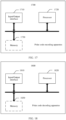
- an embodiment of this application provides a polar encoding apparatus, where the apparatus includes a memory and a processor.
- the memory is configured to store a program, instructions, or code.
- the processor is configured to invoke the program, the instructions, or the code stored in the memory, to perform the method according to the first aspect or the possible designs of the first aspect.
- the apparatus may further include an input/output interface, configured to communicate with another apparatus.
- the memory may be a physically independent unit, or may be coupled to the processor, or the processor includes the memory.
- an embodiment of this application provides a polar decoding apparatus.
- the apparatus includes a memory and a processor.
- the memory is configured to store a program, instructions, or code.
- the processor is configured to invoke the program, the instructions, or the code stored in the memory, to perform the method according to the second aspect, the third aspect, the possible designs of the second aspect, or the possible designs of the third aspect.
- the apparatus may further include an input/output interface, configured to communicate with another apparatus.
- the memory may be a physically independent unit, or may be coupled to the processor, or the processor includes the memory.
- an embodiment of this application provides a polar encoding apparatus.
- the apparatus has a function of implementing the method according to any one of the first aspect or the possible designs of the first aspect.
- the function may be implemented by hardware, or may be implemented by hardware executing corresponding software.
- the hardware or the software includes one or more modules corresponding to the foregoing function.
- the apparatus includes: an input/output interface circuit, configured to obtain to-be-encoded source bits; a logic circuit, configured to perform behavior in any one of the first aspect or the possible designs of the first aspect; and an input/output interface circuit, configured to output a source coding codeword, where the source coding codeword includes encoded source bits and assistance information.
- the polar encodingsorting apparatus may be a chip or an integrated circuit.
- an embodiment of this application provides a sorting apparatus.
- the apparatus has a function of implementing the method according to any one of the first aspect or the possible designs of the first aspect.
- the function may be implemented by hardware, or may be implemented by hardware executing corresponding software.
- the hardware or the software includes one or more modules corresponding to the foregoing function.
- the apparatus includes: an input/output interface circuit, configured to obtain to-be-decoded source information, where the to-be-decoded source information includes assistance information; a logic circuit, configured to perform behavior in any one of the second aspect or the possible designs of the second aspect; and an input/output interface circuit, configured to output a source decoding result.
- the sorting apparatus may be a chip or an integrated circuit.
- an embodiment of this application provides a polar encodingsorting apparatus.
- the apparatus has a function of implementing the method according to any one of the first aspect or the possible designs of the first aspect.
- the function may be implemented by hardware, or may be implemented by hardware executing corresponding software.
- the hardware or the software includes one or more modules corresponding to the foregoing function.
- the apparatus includes: an input/output interface circuit, configured to obtain to-be-decoded channel information; and a logic circuit, configured to perform behavior in any one of the third aspect or the possible designs of the third aspect.
- the polar encodingsorting apparatus may be a chip or an integrated circuit.
- an embodiment of this application provides a computer-readable storage medium.
- the computer-readable storage medium stores computer-readable instructions.
- the method according to the first aspect or the possible designs of the first aspect is performed.
- an embodiment of this application provides a computer-readable storage medium.
- the computer-readable storage medium stores computer-readable instructions.
- the method according to the second aspect or the possible designs of the second aspect is performed, or the method according to the third aspect or the possible designs of the third aspect is performed.
- an embodiment of this application provides a chip system.
- the chip system includes a processor, and may further include a memory.
- the memory is configured to store a program, instructions, or code.
- the processor is configured to invoke the program, the instructions, or the code stored in the memory, to perform the method according to the first aspect or the possible designs of the first aspect.
- the chip system may include a chip, or may include a chip and another discrete component.
- an embodiment of this application provides a chip system.
- the chip system includes a processor, and may further include a memory.
- the memory is configured to store a program, instructions, or code.
- the processor is configured to invoke the program, the instructions, or the code stored in the memory, to implement the method according to the second aspect or the possible designs of the second aspect, or to implement the method according to the third aspect or the possible designs of the third aspect.
- the chip system may include a chip, or may include a chip and another discrete component.
- a computer program product including instructions is provided.
- the method according to the first aspect or the possible designs of the first aspect is performed.
- a computer program product including instructions is provided.
- the method according to the second aspect or the possible designs of the second aspect is performed, or the method according to the third aspect or the possible designs of the third aspect is performed.
- Embodiments of this application provide a polar encoding method and apparatus and a polar decoding method and apparatus.
- the methods and the apparatuses are based on a same inventive concept. Because problem-resolving principles of the methods and the apparatuses are similar, mutual reference may be made to implementations of the apparatuses and the methods. Repeated parts are not described again.
- the term "and/or" describes an association relationship between associated objects and indicates that three relationships may exist.
- a and/or B may indicate the following three cases: Only A exists, both A and B exist, and only B exists.
- a plurality of in this application means two or more.
- terms such as “first” and “second” are merely used for distinguishing and description, but should not be understood as indicating or implying relative importance, or should not be understood as indicating or implying a sequence.
- the polar encoding method and the polar decoding method provided in embodiments of this application may be applied to a 5G communication system, for example, a 5G new radio (new radio, NR) system, or may be applied to various future evolved communication systems, for example, a 6th generation (6th generation, 6G) communication system or a space-air-sea-ground integrated communication system.
- a 5G communication system for example, a 5G new radio (new radio, NR) system
- 6th generation (6th generation, 6G) communication system for example, a 6th generation (6th generation, 6G) communication system or a space-air-sea-ground integrated communication system.
- FIG. 1a shows an architecture of a wireless communication system to which the polar encoding method and the polar decoding method provided in embodiments of this application may be applied.
- the wireless communication system 100 includes a transmitter 110 and a receiver 120.
- the transmitter 110 may be a network device, and the receiver 120 is a terminal device; or the transmitter 110 is a terminal device, and the receiver 120 is a network device.
- the architecture of the wireless communication system may alternatively be shown in FIG. 1b , and includes a network device 101 and a terminal device 102.
- the following describes possible implementations and functions of the network device 101 and the terminal device 102 by using examples.
- the network device 101 provides a service for the terminal device 102 within a coverage area of the network device 101.
- the network device 101 provides radio access for one or more terminal devices 102 within the coverage area of the network device 101.
- the network device 101 is a node in a radio access network (radio access network, RAN), and may also be referred to as a base station, or may be referred to as a RAN node (or device).
- RAN radio access network
- some examples of the network device 101 are a next-generation NodeB (next-generation NodeB, gNB), a next-generation evolved NodeB (next-generation evolved NodeB, Ng-eNB), a transmission reception point (transmission reception point, TRP), an evolved NodeB (evolved NodeB, eNB), a radio network controller (radio network controller, RNC), a NodeB (NodeB, NB), a base station controller (base station controller, BSC), a base transceiver station (base transceiver station, BTS), a home base station (for example, a home evolved NodeB, or a home NodeB, HNB), a baseband unit (baseband unit, BBU), or a wireless
- the network device 101 may alternatively be a satellite, and the satellite may also be referred to as a high-altitude platform, a high-altitude aircraft, or a satellite base station.
- the network device 101 may be another device that has a function of the network device.
- the network device 101 may be alternatively a device that functions as a network device in device-to-device (device to device, D2D) communication, vehicle-to-everything, or machine-to-machine (machine to machine, M2M) communication.
- the network device 101 may be any possible network device in a future communication system.
- the terminal device 102 is also be referred to as user equipment (user equipment, UE), a mobile station (mobile station, MS), a mobile terminal (mobile terminal, MT), or the like, and is a device that provides a user with voice and/or data connectivity.
- the terminal device 102 is a handheld device, a vehicle-mounted device, or the like that has a wireless connection function.
- the terminal device 102 may be a mobile phone (mobile phone), a tablet computer, a notebook computer, a palmtop computer, a mobile internet device (mobile internet device, MID), a wearable device (for example, a smartwatch, a smart band, or a pedometer), a vehicle-mounted device (for example, a vehicle-mounted device on an automobile, a bicycle, an electric vehicle, an aircraft, a ship, a train, or a high-speed train), a virtual reality (virtual reality, VR) device, an augmented reality (augmented reality, AR) device, a wireless terminal in industrial control (industrial control), a smart home device (for example, a refrigerator, a television, an air conditioner, or an electricity meter), an intelligent robot, a workshop device, a wireless terminal in self-driving (self-driving), a wireless terminal in remote medical surgery (remote medical surgery), a wireless terminal in a smart grid (smart grid), a wireless terminal in transportation safety (transportation safety), a wireless
- the terminal device 102 may be another device that has a function of the terminal device.
- the terminal device 102 may be alternatively a device that functions as a terminal device in device-to-device (device to device, D2D) communication, vehicle-to-everything, or machine-to-machine (machine to machine, M2M) communication.
- D2D device to device
- M2M machine-to-machine
- a network device that functions as a terminal device may also be considered as a terminal device.
- the polar code is also a linear block code, and a generator matrix is G N .
- the generator matrix may also be denoted as G, and the generator matrix may also be referred to as an encoding matrix.
- bits in u 1 N are used to carry information, and the bits carrying the information are referred to as information bits.
- the bits for carrying the information form an information bit set, and a set of indexes of these bits is denoted as .
- Other bits are set to fixed values pre-agreed on by a receiver and a transmitter, and are referred to as a set of fixed bits or a set of frozen bits (frozen bits).
- a set of indexes of the bits is represented by a complementary set of .
- G N (A) is a submatrix obtained by using rows corresponding to indexes in a set in G N
- Grr(AC) is a submatrix obtained by using rows corresponding to indexes in a set in G N .
- a quantity of information bits is K
- u Ac is a fixed bit set in u 1 N
- a quantity of fixed bits is (N-K)
- the bits are known bits.
- These fixed bits are usually set to 0.
- the fixed bits may be set to any value provided that the value is agreed on by the receiver and the transmitter in advance.
- encoding output of the polar code may be simplified as: where u A is the information bit set in u 1 N , u A is a row vector of a length K, that is,
- K,
- a construction process of the polar code is a selection process of the set . This determines performance of the polar code.
- the construction process of the polar code is usually as follows: It is determined, based on a mother code length N, that there are N polarization channels in total, corresponding to N rows of a generator matrix respectively, to calculate reliability of the polarization channels. Indexes of first K polarization channels with high reliability are used as elements of the set , and indexes corresponding to remaining (N-K) polarization channels are used as elements of the index set of the fixed bits.
- the set determines locations of the information bits, and the set determines locations of the fixed bits.
- An SC decoding method is an effective decoding algorithm for a polar code. After receiving a signal, a decoding device calculates a log-likelihood ratio (Log Likelihood Ratio, LLR) of the information bits one by one. If the LLR of the information bit is greater than 0, a decoding result is 0; if the LLR of the information bits is less than 0, a decoding result is 1. The fixed bits are set to 0 regardless of the LLR.
- FIG. 2a is a schematic diagram of an SC decoding calculation process. For example, there are four decoded bits. There are eight computing nodes in total in FIG.
- FIG. 2b is a schematic diagram of a decoding path in the SCL algorithm. As shown in FIG. 2b , each layer represents one decoded bit. If a decoding result is 0, a path is developed along a left subtree.
- a path is developed along a right subtree.
- L is an integer power of 2
- L paths with optimal PM values are selected for storage, and the paths continue to be developed to obtain subsequent decoded bits through decoding.
- the PM values are for determining whether the paths are good or bad, and the PM values are obtained through calculation by using the LLR.
- the PM values of the L paths are sorted in ascending order, and a correct path is selected by using the PM values. This process is repeated until the last bit is decoded.
- the source entropy may be further polarized.
- u 1 i ⁇ 1 continues to be polarized with an increase of N, but there is a range 0 ⁇ H u i
- a proportion of a part that is polarized to 1 may be obtained as H ( x ), that is, lim N ⁇ ⁇ i ⁇ N : H u i
- compression of a signal x 1 N may be converted into compression of u 1 N .
- Some bits in u 1 N may be completely determined by other bits u 1 i ⁇ 1 , and do not need to be stored, and only a part of the other part H u i
- u 1 i ⁇ 1 1 needs to stored.
- a source polarization theory as N increases, a part of a conditional entropy H u i
- u 1 i ⁇ 1 ( i 1,2, ...
- u 1 N is divided into two parts.
- One part is referred to as redundant bits (that is, bits whose conditional entropy is close to 0), and the other part is referred to as fixed bits.
- An index set of these bits is denoted as F .
- the fixed bits may also be referred to as source fixed bits
- the redundant bits may also be referred to as source redundant bits.
- Source bits include source fixed bits and source redundant bits.
- source polar decoding is basically the same as channel polar decoding. All channel log-likelihood ratios ln P y i
- x i 0 P y i
- This application provides a polar encoding method, to improve performance of source polar codes.
- a procedure of a polar encoding method is described as follows: The method is performed by a transmitter or an encoder, and the transmitter or the encoder may be a terminal device, or may be a network device.
- the transmitter performs polar encoding according to the following method, and may send an output source coding codeword to a receiver.
- the encoder performs polar encoding according to the following method, and may send an output source coding codeword to a decoder. If the transmitter or the encoder is a terminal device, the receiver or the decoder may be a network device. If the transmitter or the encoder is a network device, the receiver or the decoder may be a terminal device.
- S402. Perform first polar encoding on the to-be-encoded source bits to obtain encoded source bits.
- the first polar encoding includes first transformation and second transformation, the first transformation is polarization transformation, a mother code length corresponding to the first transformation is Ns, the polarization transformation is performed on the to-be-encoded source bits to obtain first source bits, and the second transformation is performed on the first source bits to obtain the encoded source bits.
- Ns may be an integer power of 2.
- the encoded source bits and the assistance information may be combined (combine) to obtain the source coding codeword.
- the assistance information is spliced after the encoded source bits, or the encoded source bits are spliced after the assistance information, or the assistance information is inserted in a preset position between the encoded source bits.
- FIG. 5 is a schematic diagram of the foregoing polar encoding process.
- the second transformation includes one or more of the following operations: a convolution operation, an upper triangular transformation operation, a compression operation, or an interleaving operation.
- the second transformation may be a compression operation.
- the first source bits are obtained after polarization transformation is performed on the to-be-encoded source bits; the first source bits are compressed, that is, bits corresponding to a fixed bit set F in the first source bits are reserved, and redundant bits are deleted; and the encoded source bits are obtained.
- the second transformation may be a convolution operation and a compression operation.
- the first source bits are obtained after polarization transformation is performed on the to-be-encoded source bits.
- the compression operation is performed on the first source bits.
- the compression operation is: For bits obtained after the convolution operation is performed on the first source bits, bits corresponding to the fixed bit set F are reserved, and redundant bits are deleted; and the encoded source bits are obtained.
- the convolution operation may cause an additional association between polarized bits to some extent. Compared with a method in which no convolution operation is performed, in this method, more original information can be retained at a same compression rate, and a lower decoding error rate can be achieved.
- the bits corresponding to the fixed bit set F may be bits that are in the bits obtained after the convolution operation and that correspond to the source fixed bits in original F.
- the second transformation may be an upper triangular transformation operation and a compression operation.
- the first source bits are obtained after polarization transformation is performed on the to-be-encoded source bits.
- the compression operation is performed on the first source bits.
- the compression operation is: For bits obtained after the upper triangular transformation operation is performed on the first source bits, bits corresponding to the fixed bit set F are reserved, and redundant bits are deleted; and the encoded source bits are obtained.
- the upper triangular operation is to multiply the first source bits by an upper triangular matrix.
- the upper triangular operation may cause an additional association between polarized bits to some extent. Compared with a method in which no upper triangular operation is performed, in this method, more original information can be retained at a same compression rate, and a lower decoding error rate can be achieved.
- the determining assistance information based on the first source bits may be implemented in the following manner:
- the first decoding is SCL decoding, and SCL decoding is performed on the encoded source bits to obtain L candidate vectors, where L is a positive integer, and L may be a decoding path width.
- the L candidate vectors are compared with the first source bits; and a first vector in the L candidate vectors that is the same as the first source bits is determined, where information about a sequence number of the first vector in the L candidate vectors is the indication information.
- the indication information may be a binary representation of a sequence number of a candidate vector.
- decoding may be performed once based on an encoding result during encoding, to determine whether the encoding is successful.
- the assistance information is generated based on a correct result indicating successful decoding, and the assistance information is in the source coding codeword.
- a decoding result indicated by the assistance information may be output during source decoding, thereby helping improve performance of the source polar codes.
- short code performance of the source polar codes can be improved.
- a size of a decoding list required to achieve a same bit error rate can be greatly reduced, that is, decoding complexity can be greatly reduced.
- the embodiment in FIG. 4 describes the polar encoding method.
- An embodiment of this application further provides a polar decoding method, to improve performance of source polar codes.
- the polar decoding method is a separately protected solution in embodiments of this application, or may be combined based on the polar encoding scheme provided in FIG. 4 , to form a solution that needs to be protected in embodiments of this application.
- a procedure of a polar decoding method is as follows: The method is performed by a receiver or a decoder, and the receiver or the decoder may be a terminal device or a network device.
- the receiver receives to-be-decoded source information from a transmitter, and performs polar decoding according to the following method.
- the decoder receives to-be-decoded source information from an encoder, and performs polar decoding according to the following method. If the receiver or the decoder is a terminal device, the transmitter or the encoder may be a network device. If the receiver or the decoder is a network device, the transmitter or the encoder may be a terminal device.
- the to-be-decoded source information includes assistance information.
- S602. Perform first decoding on the to-be-decoded source information to obtain L candidate vectors, where L is a positive integer.
- the first decoding may be SCL decoding or other decoding, for example, list decoding of PAC codes.
- L is a decoding path width L, and L may be an integer power of 2.
- Source decoding is performed by using the assistance information, so that decoding performance of source polar codes can be improved.
- the assistance information is check bits.
- the L candidate vectors may be sequentially checked based on the check bits and in an order of weight values; and when the check succeeds, a candidate vector on which the check succeeds is determined as the first vector.
- first decoding is performed on the to-be-decoded source information to obtain the L candidate vectors.
- the L candidate vectors each have a weight value, and the weight values of the L candidate vectors may determine an order of the L candidate vectors, for example, in descending order of the weight values, or in ascending order of the weight values.
- the weight is a PM value
- the candidate vectors may be sequentially checked based on the check bits and in an order of PM values of the L candidate vectors.
- one candidate vector is sequentially selected in descending order of absolute values of the PM values of the L candidate vectors, and the candidate vector is checked based on the check bits. If the check succeeds, the vector on which the check succeeds is the first vector. If the check fails, a next selected candidate vector continues to be checked based on the check bits. If the check succeeds, the vector on which the check succeeds is the first vector. In this way, the first vector is selected.
- the manner a may be combined with the manner 1 in the foregoing source polar encoding scheme.
- the encoder performs check coding on the first source bits to obtain check bits, where the check bits are the assistance information.
- the output source coding codeword includes the encoded source bits and the check bits.
- the decoder performs decoding based on the check bits obtained by the encoder through encoding, so that a correct decoding result can be obtained through screening by using the check bits during decoding, thereby helping improve performance of source polar codes. Especially in a scenario with a limited code length, short code performance of the source polar codes can be improved.
- the assistance information is indication information
- the indication information indicates a candidate vector.
- the indication information indicates a sequence number of a candidate vector.
- the first vector corresponding to the sequence number indicated by the indication information in the L candidate vectors is determined based on the indication information.
- the indication information herein may indicate one of the L candidate vectors.
- the manner b may be combined with the manner 2 in the foregoing source polar encoding scheme.
- the encoder performs SCL decoding on the encoded source bits to obtain L candidate vectors.
- the L candidate vectors are compared with the first source bits; and a first vector in the L candidate vectors that is the same as the first source bits is determined, where information about a sequence number of the first vector in the L candidate vectors is the indication information.
- the decoder may determine, based on the indication information, the first vector corresponding to the sequence number indicated by the indication information in the L candidate vectors. In this way, decoding may be performed once based on an encoding result during encoding, to determine whether the encoding is successful.
- the assistance information is generated based on a correct result indicating successful decoding, and the assistance information is in the source coding codeword.
- a decoding result indicated by the assistance information may be output during source decoding, thereby helping improve performance of the source polar codes.
- short code performance of the source polar codes can be improved.
- a size of a decoding list required to achieve a same bit error rate can be greatly reduced, that is, decoding complexity can be greatly reduced.
- the polar decoding method is described above. Based on a same technical concept, in the first decoding, SC decoding is performed on the to-be-decoded source information based on SC decoding, to obtain a vector.
- the assistance information is the check bits, and a vector is checked based on the assistance information (that is, based on the check bits). If the check on the vector succeeds, a polarization transformation is performed on the vector, to obtain a source decoding result. If the vector check fails, a previous procedure of the source decoding is returned to, for example, channel decoding is returned to, and a next result of the channel decoding is selected according to a channel decoding rule, to perform source decoding.
- the source decoding is to repeat the foregoing process: performing SC decoding on to-be-decoded source information to obtain a vector, and checking the vector based on the check bits; and if the check succeeds, performing polarization transformation on the vector to obtain a source decoding result.
- FIG. 7a A schematic diagram of a process of the encoding/decoding method is shown in FIG. 7a .
- a specific process may be described as follows:
- Polarization transformation is performed on û to obtain a source decoding result ⁇ .
- FIG. 7b A schematic diagram of a process of the encoding/decoding method is shown in FIG. 7b .
- a specific process may be described as follows:
- Polarization transformation is performed on û to obtain a source decoding result ⁇ .
- a list decoder for PAC codes may be used during decoding.
- the list decoder for the PAC codes is similar to an SCL decoder for polar codes, but impact of convolution needs to be considered in a decoding process.
- FIG. 7c A schematic diagram of a process of the encoding/decoding method is shown in FIG. 7c .
- a specific process may be described as follows:
- Encoding process Polarization transformation is performed on to-be-encoded source bits s to obtain u; bits corresponding to a fixed bit set F in u are reserved, and redundant bits are deleted; list decoding whose list size is L is performed by using u F , to obtain a candidate result list, where the candidate result list includes L candidate vectors; and the L candidate vectors are compared with the first source bits u F , to determine a first vector that is in the L candidate vectors and that is the same as the first source bits u F .
- the first vector is a correct path, and a binary representation i s of the first vector is put into an encoding result.
- Polarization transformation is performed on û to obtain a source decoding result ⁇ .
- the assistance information is indication information
- the second transformation is a convolution operation (or an upper triangular transformation operation) and a compression operation.
- FIG. 7d A schematic diagram of a process of the encoding/decoding method is shown in FIG. 7d . A specific process may be described as follows:
- Encoding process Polarization transformation is performed on to-be-encoded source bits s to obtain v; a convolution operation (or an upper triangular transformation operation) is performed on v once to obtain u; bits corresponding to a fixed bit set F in u are reserved, and redundant bits are deleted; list decoding whose list size is L is performed by using u F , to obtain a candidate result list, where the candidate result list includes L candidate vectors; and the L candidate vectors are compared with the first source bits u F , to determine a first vector that is in the L candidate vectors and that is the same as the first source bits u F .
- the first vector is a correct path, and a binary representation i s of the first vector is put into an encoding result.
- Polarization transformation is performed on û to obtain a source decoding result ⁇ .
- the following describes another polar encoding method provided in an embodiment of this application.
- the method is a joint source-channel coding method.
- the method may be combined with the source coding method provided in the foregoing embodiment, and a channel coding method may be added on this basis.
- a mother code length corresponding to the second polar encoding is Nc, and Nc may be an integer power of 2.
- the second polar encoding may be polar channel coding.
- the first K polarization channels with high reliability are locations of to-be-coded bits, and remaining locations are locations of fixed bits.
- the polarization channel may also be referred to as a polarized subchannel, a mother code length is Nc, and first K polarized subchannels with high reliability in the Nc polarized subchannels may be referred to as information subchannels.
- the to-be-encoded bits include the source coding codeword, and the source coding codeword is mapped to information subchannels.
- check coding may be performed on the source coding codeword to obtain a check coding codeword.
- CRC coding is performed on the source coding codeword to obtain a CRC check coding codeword.
- the to-be-encoded bits include a source coding codeword and the check coding codeword, and the source coding codeword and the check coding codeword are mapped to information subchannels.
- mapping is implemented, the to-be-coded channel bits are obtained; and then second polar encoding is performed on the to-be-coded channel bits to obtain the foregoing channel coding codeword, and the channel coding codeword is output.
- mapping the source coding codeword to the information subchannels provides an optional implementation of mapping the source coding codeword to the information subchannels. It may be understood that, when check coding is performed on the source coding codeword, the source coding codeword and the check coding codeword need to be mapped to the information subchannels. For the descriptions of a mapping manner, in this specification, that no check coding is performed on the source coding codeword is used as an example, that is, the source coding codeword is mapped to the information subchannels. The described method may be applied to a scenario in which the source coding codeword and the check coding codeword are mapped to the information subchannels.
- the mapping rule A is natural mapping.
- the source coding codeword is sequentially mapped to the information subchannels in a natural order to obtain the to-be-encoded channel bits.
- the mapping rule B is interleaving mapping.
- the source coding codeword is mapped to the information subchannels according to the mapping rule B, to obtain the to-be-encoded channel bits.
- the source coding codeword includes m flag bits. Reliability of the m flag bits is higher than reliability of other bits in the source coding codeword.
- the flag bit may also have another name. This is not limited in this application.
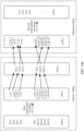
- an encoder may mark the m flag bits for reference in an interleaving mapping process of channel coding. Due to a limited code length, some of polarized source bits have specific reliability (that is, conditional entropy is small and close to 0), but are insufficient to be deleted. These bits may be for providing additional soft information for channel decoding. When a source code is constructed, m fixed bits with high reliability (that is, low conditional entropy) are marked as flag bits.
- the first K polarized subchannels with high reliability in the Nc polarized subchannels are information subchannels, that is, a quantity of the information subchannels is K.
- the flag bit is represented by a shadow.
- the source coding codeword is mapped to the information subchannels in a natural order to obtain the channel information bit sequence.
- the mapping in the natural order is: The 1 st bit of the source coding codeword is mapped to the 1 st information subchannel, the 2 nd bit of the source coding codeword is mapped to the second information subchannel, and so on, a K th bit of the source coding codeword is mapped to a K th information subchannel.
- the m flag bits are correspondingly mapped to the m information subchannels.
- a sequence number of an information subchannel to which an i th flag bit in the m flag bits is mapped is x i in the channel information bit sequence
- a sequence number of an information subchannel to which an (i+1) th flag bit in the m flag bits is mapped is xi+i in the channel information bit sequence.
- sequence number range [x i , x i+1 ) indicates that sequence numbers start from an information subchannel to which the i th flag bit in the m flag bits is mapped and end with an information subchannel previous to an information subchannel to the (i+1) th flag bit in the m flag bits is mapped.
- a sequence number of an information subchannel to which the 1 st flag bit in the m flag bits is mapped is x 1 in the channel information bit sequence
- a sequence number of an information subchannel to which the 2 nd flag bit in the m flag bits is mapped is x 2 in the channel information bit sequence
- a bit mapped to an information subchannel whose sequence number is x 1 and a bit mapped to an information subchannel with the lowest reliability in information subchannels whose sequence number range is [x 1 , x 2 ) are exchanged.
- the interleaving mapping process is divided into two steps: natural order based mapping and exchange.
- the natural mapping step may be omitted according to the same mapping rule, and the source coding codeword is directly mapped to the information subchannels to obtain the to-be-encoded channel bits. Results obtained in the two manners are the same.
- FIG. 9 is still used as an example.
- Bits in the source coding codeword are mapped to information subchannels one by one according to a natural order. When the 1 st flag bit is encountered, the 1 st flag bit is directly mapped to an information subchannel with the lowest reliability in [x 1 , x 2 ). When a bit corresponding to the information subchannel with the lowest reliability in [x 1 , x 2 ) in the source coding codeword is encountered, the bit is mapped to an information subchannel corresponding to the 1 st flag bit.
- parallel mapping may be performed according to a mapping rule.
- the source coding codeword is mapped to the information subchannels in parallel based on a mapping pattern corresponding to the mapping rule.
- the polar encoding method provided in the embodiment in FIG. 8 is a joint source-channel coding method.
- An embodiment of this application further provides a polar decoding method, which may be referred to as a joint source-channel decoding method, to improve performance of source polar codes.
- the polar decoding method is a separately protected solution in embodiments of this application, or may be combined based on the polar encoding scheme provided in FIG. 8 , to form a solution that needs to be protected in embodiments of this application.
- a procedure of a polar decoding method is as follows: The method is performed by a receiver or a decoder, and the receiver or the decoder may be a terminal device or a network device.
- the receiver receives to-be-decoded source information from a transmitter, and performs polar decoding according to the following method.
- the decoder receives to-be-decoded source information from an encoder, and performs polar decoding according to the following method. If the receiver or the decoder is a terminal device, the transmitter or the encoder may be a network device. If the receiver or the decoder is a network device, the transmitter or the encoder may be a terminal device.
- This step may correspond to step S601 of obtaining the to-be-decoded source information.
- the channel decoding result includes L1 to-be-decoded candidate source vectors whose reliability is in descending order, and the to-be-decoded source information is one of the L1 to-be-decoded candidate source vectors.
- a to-be-decoded candidate source vector may be selected as the to-be-decoded source information based on a path metric value or reliability.
- a method for performing first decoding on the to-be-decoded source information refer to the decoding process in the embodiment in FIG. 6 , or another decoding method, for example, SC decoding, may be used.
- channel decoding is first performed, and candidate channel decoding paths are output. For example, L channel decoding paths are output, where L is a decoding path width.
- a channel decoding path with the highest reliability is selected based on the path metric value, and first decoding, that is, source decoding, is performed on the channel decoding path with the highest reliability, to obtain a source decoding result.
- a decoder may further perform decoding according to the following method: Channel decoding is first performed, and candidate channel decoding paths are output. For example, L channel decoding paths are output, where L is a decoding path width.
- first decoding that is, source decoding
- a source decoding result is checked. If the check succeeds, the source decoding result is output. If the check fails, first decoding is then performed on a channel decoding path with the second highest reliability, and an obtained source decoding result of the channel decoding path with the second highest reliability is checked.
- the source decoding result is output. If the check succeeds, the source decoding result is output. If the check fails, first decoding continues to be performed until the check succeeds and a source decoding result is output, or until all channel decoding paths are traversed. If all the channel decoding paths are traversed, and there is no source decoding result that is successfully checked, a source decoding result of a channel decoding path with the highest reliability may be output.
- the coding process includes a source coding process and a channel coding process.
- the source coding process is as follows: First polar encoding is performed on to-be-encoded source bits s, to obtain and output a source coding codeword s comp .
- First polar encoding is performed on to-be-encoded source bits s, to obtain and output a source coding codeword s comp .
- For the source coding process refer to the coding process in any one of the foregoing application scenarios 1 to 4. Details are not described herein again.
- the channel coding process is as follows: Check coding, for example, CRC coding, is performed on an output source coding codeword s comp to obtain a check coding codeword c c ; s comp and c c are mapped to information subchannels in a natural order, that is, s comp and c c are placed in a natural mapping manner on information bits of an input sequence u of a channel polar code encoder; and polarization transformation is performed on u to obtain a final codeword x .
- Check coding for example, CRC coding
- a decoding method may be a list decoding method.
- Candidate results in the candidate decoding result list are sorted in descending order of reliability or probabilities, and a value of i may start from 1, that is, start from a candidate result with the highest reliability or probability.
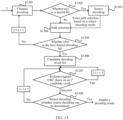
- an application scenario of the method used in FIG. 11a is consistent with that of the method used in FIG. 11b .
- the encoding method in FIG. 11a uses the encoding process in the application scenario 1
- the decoding method in FIG. 11b uses the decoding process in the application scenario 1.
- source decoding is performed on the candidate decoding result that is successfully checked. If there is a result on which the source CRC can succeed, it is considered that the source decoding result can be determined, and further polarization transformation is performed on the result on which the source CRC succeeds, to obtain the source decoding result. If there is no result on which the source CRC can succeed, S1103 is returned to.
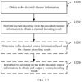
- the polar decoding method in the embodiment in FIG. 10 is joint source-channel decoding, and source decoding is performed after all bits in channel decoding are decoded.
- a procedure of another polar decoding method is as follows: The method is performed by a receiver or a decoder, and the receiver or the decoder may be a terminal device or a network device.
- the receiver receives to-be-decoded source information from a transmitter, and performs polar decoding according to the following method.
- the decoder receives to-be-decoded source information from an encoder, and performs polar decoding according to the following method. If the receiver or the decoder is a terminal device, the transmitter or the encoder may be a network device. If the receiver or the decoder is a network device, the transmitter or the encoder may be a terminal device.
- S1202. Perform second decoding on the to-be-decoded channel information to obtain a channel decoding result.
- a path metric value corresponding to an n1 th channel information bit is determined based on the following information: a path metric value corresponding to an (n1-1) th channel information bit, a path metric increment corresponding to the n1 th channel information bit, and a metric value corresponding to an n2 th source fixed bit obtained when first decoding is performed on the to-be-decoded source information to obtain the n2 th source fixed bit, where n1 and n2 are both positive integers.
- a channel decoding process when some bits are decoded, source decoding is performed on the some bits based on a channel decoding result of the some bits, and a value of the source decoding of the some bits is fed back to channel decoding of a next bit.
- soft information of the source decoding can assist decoding of channel information bits.
- paths for all bits before the n1 th channel information bit need to be considered, including a channel information bit and a channel fixed bit.
- the second decoding is performed on the to-be-decoded channel information, where the second decoding may be referred to as channel decoding.
- channel decoding when an x th information bit u x is decoded, an obtained path metric value corresponding to the x th information bit is a path metric value corresponding to a decoded (x-1) th information bit and a path metric increment corresponding to the x th information bit.
- channel decoding when channel decoding is performed on some special bits, source decoding is performed, and a channel decoding result of the special bits is obtained with assistance based on the source decoding.
- channel decoding may be performed according to a conventional channel decoding method.
- n1 may be a sequence number in 1 to K.
- first decoding that is, source decoding
- a metric value corresponding to the n2 th source fixed bit is obtained.
- a path metric value corresponding to the n1 th channel information bit is obtained with assistance based on the obtained metric value corresponding to the n2 th source fixed bit.
- An information subchannel on which the n1 th channel information bit is located has a mapping relationship with the n2 th source fixed bit in the to-be-decoded source information.
- information about the 1 st to the (n1-1) th channel information bits is obtained.
- Information about all source bits before the n2 th source fixed bit may be determined based on the information about the 1 st to the (n1-1) th channel information bits, where the source bits include source fixed bits and source redundant bits. For example, 1-(n2-1) source fixed bits are obtained by using 1-(n1-1) channel information bits.
- source decoding may be performed on a source redundant bit previous to the n2 th source fixed bit, to obtain the information about all the source bits before the n2 th source fixed bit.
- a metric value corresponding to the n2 th source fixed bit may be determined based on the information about all the source bits before the n2 th source fixed bit. For example, information about the 1 st to the (n2-1) th source fixed bits may be determined based on the information about the 1 st to the (n1-1) th channel information bits, and information about source redundant bits before the n2 th source fixed bit may be learned based on the information about the 1 st to the (n2-1) th source fixed bits.
- the information about all the source bits before the n2 th source fixed bit may be obtained. Then, the metric value corresponding to the n2 th source fixed bit is determined based on the information about all the source bits before the n2 th source fixed bit.
- soft information of the n2 th source fixed bit may be first determined based on the information about all the source bits before the n2 th source fixed bit, and the metric value corresponding to the n2 th source fixed bit is determined based on the soft information of the n2 th source fixed bit.
- the path metric value corresponding to the n1 th channel information bit may be determined based on a path metric value corresponding to a decoded (n1-1) th information bit and a path metric increment corresponding to the n1 th information bit.
- the path metric value corresponding to the n1 th channel information bit is determined based on the following three: a path metric value corresponding to the decoded (n1-1) th information bit, the path metric increment corresponding to the n1 th information bit, and the metric value corresponding to the n2 th source fixed bit.
- the path metric value corresponding to the n1 th channel information bit is a sum of the foregoing three values.
- the special bit may be a flag bit, and the flag bit is the flag bit described in the mapping rule B in the foregoing encoding embodiment.
- the source coding codeword includes a flag bit, and the source coding codeword is mapped to the information subchannels according to the mapping rule B to obtain to-be-encoded channel bits.
- the flag bit may be used as a special bit, and channel decoding is performed based on the flag bit.
- a value of n1 may be a sequence number of an information subchannel corresponding to each flag bit in K information subchannels.
- Channel decoding is performed on the to-be-decoded channel information.
- source decoding is then performed on the to-be-decoded source information.
- a source bit corresponding to the flag bit is decoded, a path metric increment corresponding to the source bit corresponding to the flag bit is obtained.
- mapping relationship between an information subchannel on which the flag bit is located and a source bit. For determining of the mapping relationship, refer to the foregoing mapping rule B.
- the mapping relationship is interleaving mapping
- the interleaving mapping is: sequentially mapping encoded source bits to information subchannels in a natural order to obtain a channel information bit sequence, where m bits in the encoded source bits are flag bits, and m is a positive integer; and exchanging a bit mapped to an information subchannel whose sequence number is x i and a bit mapped to an information subchannel whose sequence number is x j , to obtain to-be-encoded channel bits, where x i is a sequence number, in the channel information bit sequence, of an information subchannel to which an i th flag bit in the m flag bits is mapped, and x j is a sequence number, in the channel information bit sequence, of an information subchannel with lowest reliability in information subchannels whose sequence number range is [x i , x i+1 ), where xi+i is a sequence number, in the channel information bit sequence, of an information subchannel to which an (i+1) th flag bit in
- the encoder performs encoding according to the mapping rule B
- the decoder may also determine, according to the mapping rule B, a source bit corresponding to the flag bit during decoding, and assist in determining a decoding result of the flag bit based on a path metric increment corresponding to the source bit.
- the encoder and the decoder may negotiate the mapping rule B in advance, or the mapping rule B is specified in a protocol.
- the metric value corresponding to the n2 th source fixed bit is a path metric increment corresponding to the n2 th source fixed bit.
- ⁇ PMs represents a path metric increment corresponding to each source bit during source decoding.
- v s ( n2 ) indicates the n2 th source fixed bit.
- ⁇ PM s ( v s ( n 2)) represents the path metric increment corresponding to the n2 th source fixed bit.
- PM 1 n1 represents the path metric value corresponding to the n1 th channel information bit.
- PM 1 n 1 ⁇ 1 indicates a path metric value corresponding to the decoded (n1-1) th information bit.
- ⁇ PM ( u n1 ) indicates the path metric increment corresponding to the n1 th information bit.
- first decoding that is, source decoding
- Source decoding may be performed by using information obtained through channel decoding.
- the special bit may be any bit.
- the special bit may be an information bit previous to a channel fixed bit location, and is denoted as an n1 th channel information bit.
- the channel fixed bit is a channel frozen bit.
- a mapping relationship between an information subchannel on which the n1 th channel information bit is located and the n2 th source fixed bit in the to-be-decoded source information may be natural sequential mapping, or may be interleaving mapping. This is not limited in this embodiment of this application.
- a value of n1 may be a sequence number corresponding to an information bit previous to each fixed bit location.
- Channel decoding is performed on the to-be-decoded channel information.
- source decoding is then performed on the to-be-decoded source information.
- a source bit corresponding to the n1 th information bit is the n2 th source fixed bit.
- source decoding is performed on the n2 th source fixed bit, a path metric value corresponding to the 1 st to the n2 th source fixed bits is obtained.
- the metric value corresponding to the n2 th source fixed bit is a path metric value corresponding to the 1 st to the n2 th source fixed bits. It should be noted that, for the path metric value corresponding to the 1 st to the n2 th source fixed bits, a path of a source information bit before the n2 th source fixed bit does not need to be considered, and only a path of a source fixed bit needs to be considered.
- PMs represents a path metric value corresponding to each source bit during source decoding.
- PM 1 n1 represents the path metric value corresponding to the n1 th channel information bit.
- PM 1 n1 ⁇ 1 indicates a path metric value corresponding to the decoded (n1-1) th information bit.
- ⁇ PM ( u n1 ) indicates the path metric increment corresponding to the n1 th information bit.
- first decoding that is, source decoding
- Source decoding may be performed by using information obtained through channel decoding.
- the decoding method provided in the embodiment in FIG. 12 provides a channel decoding process. It may be understood that, when joint source-channel decoding is performed, after the second decoding is performed on the to-be-decoded channel information to obtain the channel decoding result in S1202, source decoding may be further performed. Optionally, after S1202, the method further includes the following steps.
- a method for performing first decoding on the to-be-decoded source information refer to the decoding process in the embodiment in FIG. 6 , or another decoding method, for example, SC decoding, may be used.
- the encoder performs encoding by using the embodiment in FIG. 8
- the decoder performs decoding by using the embodiment in FIG. 12 .
- the coding process includes a source coding process and a channel coding process.
- the source coding process is as follows: First polar encoding is performed on to-be-encoded source bits s, to obtain and output a source coding codeword s comp .
- First polar encoding is performed on to-be-encoded source bits s, to obtain and output a source coding codeword s comp .
- For the source coding process refer to the coding process in any one of the foregoing application scenarios 1 to 4. Details are not described herein again.
- the channel coding process is as follows: Check coding, for example, CRC coding, is performed on an output source coding codeword s comp to obtain a check coding codeword c c ; s comp and c c are mapped to information subchannels in a natural order, that is, s comp and c c are placed in a natural mapping manner on information bits of an input sequence u of a channel polar code encoder; and polarization transformation is performed on u to obtain a final codeword x.
- Check coding for example, CRC coding
- the decoding process is shown in FIG. 13 .
- the channel decoding method may be a list decoding method.
- S1303. Perform source decoding on to-be-decoded source information.
- source decoding is performed on a source fixed bit corresponding to u(j)
- a metric value of the source fixed bit corresponding to u(j) is obtained.
- the special bit is a flag bit
- the value of the source fixed bit corresponding to u(j) is a path metric increment corresponding to the source fixed bit corresponding to u(j).
- the special bit is any bit, for example, an information bit previous to a channel fixed bit location
- the value of the source fixed bit corresponding to u(j) is a path metric value of the source fixed bit corresponding to u(j).
- a path metric value corresponding to each channel decoding path u(j) may be determined based on the path metric increment corresponding to u(j) and a path metric value corresponding to a (j-1) th channel information bit u(j-1).
- a path is selected based on the path metric value corresponding to each channel decoding path u(j).
- a path metric value corresponding to each channel decoding path u(j) may be determined based on the path metric increment corresponding to u(j), a path metric value corresponding to a (j-1) th channel information bit u(j-1), and the metric value that is of the source fixed bit corresponding to u(j) and that is obtained in S1303.
- a path is selected based on the path metric value corresponding to each channel decoding path u(j).
- S1305. Determine whether a bit is the last channel decoding bit; if yes, obtain L candidate vectors and go to S1306; otherwise, return to S1301, and continue to decode a next channel decoding bit.
- a process after S1306 is a source decoding process. For details, refer to the description of the source decoding method in FIG. 12 .
- Candidate results in the candidate decoding result list are sorted in descending order of reliability or probabilities, and a value of i may start from 1, that is, start from a candidate result with the highest reliability or probability.
- Bits in v s include source fixed bits and redundant bits. The redundant bits are deleted, and the redundant bits are framed by dashed line boxes in source coding in FIG. 14a and FIG. 14b .
- check coding for example, CRC check coding
- a CRC check coding codeword of v s is added at the tail after the redundant bits are deleted
- a source coding codeword s' ⁇ s' (1), s' (2),..., s' ( K s ) ⁇ is output in the source coding, and then channel coding is entered.
- the channel fixed bits are framed by dashed line boxes in source coding in FIG. 14a and FIG. 14b .
- the source coding codeword s ' ⁇ s' (1), s' (2),..., s' ( K s ) ⁇ is mapped to an information subchannel in u c .
- a mapping manner may be a mapping rule A, which is shown in FIG. 14a ; or the mapping manner may be a mapping rule B, which is shown in FIG. 14b .
- embodiments of this application further provide a polar encoding apparatus and a polar decoding apparatus.
- the polar encoding apparatus and the polar decoding apparatus may include a hardware structure and/or a software module.
- the foregoing functions are implemented in a form of a hardware structure, a software module, or a hardware structure and a software module. Whether a function in the foregoing functions is performed by using the hardware structure, the software module, or the combination of the hardware structure and the software module depends on particular applications and design constraints of the technical solutions.
- an embodiment of this application further provides a polar encoding apparatus 1500.
- the polar encoding apparatus 1500 may be a polar code coding apparatus, an apparatus in the polar encoding apparatus, or an apparatus that can be used by matching with the polar encoding apparatus.
- the polar encoding apparatus 1500 may be a terminal device or a network device.
- the polar encoding apparatus 1500 may include a module for performing, in a one-to-one correspondence, the method/operation/step/action related to the polar encoding method in the foregoing method embodiments.
- the module may be a hardware circuit, may be software, or may be implemented by a hardware circuit in combination with software.
- the polar encoding apparatus 1500 may include a processing module 1501 and an input/output module 1502.
- the processing module 1501 is configured to: obtain to-be-encoded source bits; perform first polar encoding on the to-be-encoded source bits to obtain encoded source bits, where the first polar encoding includes first transformation and second transformation, the first transformation is polarization transformation, a mother code length corresponding to the first transformation is Ns, the polarization transformation is performed on the to-be-encoded source bits to obtain first source bits, and the second transformation is performed on the first source bits to obtain the encoded source bits; and determine assistance information based on the first source bits.
- the input/output module 1502 is configured to output a source coding codeword, where the source coding codeword includes the encoded source bits and the assistance information.
- the second transformation includes one or more of the following operations: a convolution operation, an upper triangular transformation operation, a compression operation, or an interleaving operation.
- the processing module 1501 when determining the assistance information based on the first source bits, is configured to: perform check coding on the first source bits to obtain check bits, where the check bits are the assistance information.
- the processing module 1501 when determining the assistance information based on the first source bits, is configured to: perform first decoding on the encoded source bits to obtain at least one candidate decoding result; determine a first decoding result that is in the at least one candidate decoding result and that matches the first source bits; and determine that indication information of the first decoding result is the assistance information.
- the processing module 1501 when performing first decoding on the encoded source bits to obtain the at least one candidate decoding result, is configured to perform first decoding on the encoded source bits to obtain L candidate vectors, where L is a positive integer.
- the processing module 1501 is configured to: compare the L candidate vectors with the first source bits; and determine a first vector in the L candidate vectors that is the same as the first source bits, where information about a sequence number of the first vector in the L candidate vectors is the indication information.
- the processing module 1501 is further configured to: perform second polar encoding on the source coding codeword to obtain a channel coding codeword, where a mother code length corresponding to the second polar encoding is Nc.
- the input/output module is further configured to output the channel coding codeword.
- m bits in the source coding codeword are flag bits, and m is a positive integer.
- the processing module 1501 is configured to: map, according to a mapping rule, the source coding codeword to information subchannels of a polarization subchannel of the second polar encoding, to obtain to-be-encoded channel bits, where the mapping rule includes interleaving mapping, and the interleaving mapping is: sequentially mapping the source coding codeword to the information subchannels in a natural order to obtain a channel information bit sequence; and exchanging a bit mapped to an information subchannel whose sequence number is x i and a bit mapped to an information subchannel whose sequence number is x j , to obtain the to-be-encoded channel bits, where x i is a sequence number, in the channel information bit sequence, of an information subchannel to which an i th flag bit in the m flag bits is mapped, and x j is
- reliability of the flag bit is higher than reliability of other bits except the m flag bits in the encoded source bits.
- the processing module 1501 may further perform other operations of the encoding method in the foregoing method embodiments. Details are not described herein again.
- an embodiment of this application further provides a polar decoding apparatus 1600.
- the polar decoding apparatus 1600 may be a polar decoding apparatus, an apparatus in the polar decoding apparatus, or an apparatus that can be used by matching with the polar decoding apparatus.
- the polar decoding apparatus 1600 may be a terminal device or a network device.
- the polar decoding apparatus 1600 may include a module for performing, in a one-to-one correspondence, the method/operation/step/action related to the polar decoding method in the foregoing method embodiments.
- the module may be a hardware circuit, may be software, or may be implemented by a hardware circuit in combination with software.
- the polar decoding apparatus 1600 may include a processing module 1601 and an input/output module 1602.
- the processing module 1601 is configured to: obtain to-be-decoded source information, where the to-be-decoded source information includes assistance information; perform first decoding on the to-be-decoded source information to obtain L candidate vectors, where L is a positive integer; determine a first vector in the L candidate vectors based on assistance information, where the assistance information is check bits or indication information, and the indication information indicates a sequence number of the first vector in the L candidate vectors; and perform polarization transformation on the first vector to obtain a source decoding result.
- the input/output module 1602 is configured to output the source decoding result.
- the assistance information is check bits; and when determining the first vector in the L candidate vectors based on assistance information, the processing module 1601 is configured to: sequentially check, based on the check bits, the L candidate vectors in descending order of reliability; and when the check succeeds, determine a candidate vector on which the check succeeds as the first vector.
- the assistance information is indication information
- the indication information indicates a sequence number of the first vector in the L candidate vectors.
- the processing module 1601 is configured to: determine, based on the indication information, the first vector corresponding to the sequence number indicated by the indication information in the L candidate vectors.
- the processing module 1601 when obtaining the to-be-decoded source information, is configured to: perform second decoding on to-be-decoded channel information to obtain a channel decoding result, where the channel decoding result includes L1 to-be-decoded candidate source vectors in descending order of reliability, and the to-be-decoded source information is one of the L1 to-be-decoded candidate source vectors.
- the input/output module 1602 is configured to obtain to-be-decoded channel information.
- the processing module 1601 is configured to perform second decoding on the to-be-decoded channel information to obtain a channel decoding result, where a path metric value corresponding to an n1 th channel information bit is determined based on the following information: a path metric value corresponding to an (n1-1) th channel information bit, a path metric increment corresponding to the n1 th channel information bit, and a metric value corresponding to an n2 th source fixed bit obtained when first decoding is performed on the to-be-decoded source information to obtain the n2 th source fixed bit, where n1 and n2 are both positive integers.
- the processing module 1601 is configured to obtain a path metric value corresponding to the 1 st to the n2 th source fixed bits when second decoding is performed on the to-be-decoded source information to obtain the n2 th source fixed bit.
- the processing module 1601 is configured to obtain a path metric increment corresponding to the n2 th source fixed bit when second decoding is performed on the to-be-decoded source information to obtain the n2 th source fixed bit.
- an information subchannel on which the n1 th channel information bit is located has a mapping relationship with the n2 th source fixed bit in the to-be-decoded source information.
- the mapping relationship is interleaving mapping
- the interleaving mapping is: sequentially mapping encoded source bits to information subchannels in a natural order to obtain a channel information bit sequence, where m bits in the encoded source bits are flag bits, and m is a positive integer; and exchanging a bit mapped to an information subchannel whose sequence number is x i and a bit mapped to an information subchannel whose sequence number is x j , to obtain to-be-encoded channel bits, where x i is a sequence number, in the channel information bit sequence, of an information subchannel to which an i th flag bit in the m flag bits is mapped, and x j is a sequence number, in the channel information bit sequence, of an information subchannel with lowest reliability in information subchannels whose sequence number range is [x i , x i+1 ), where xi+i is a sequence number, in the channel information bit sequence, of an information subchannel to which an (i+1) th flag bit in
- the path metric value corresponding to the n1 th channel information bit is a sum of the following three: the path metric value corresponding to the (n1-1) th channel information bit, the path metric increment corresponding to the n 1 th channel information bit, and the metric value corresponding to the n2 th source fixed bit obtained when second decoding is performed on to-be-decoded source information to obtain the n2 th source fixed bit.
- the processing module 1601 is further configured to: determine the to-be-decoded source information based on the channel decoding result; perform first decoding on the to-be-decoded source information to obtain L candidate vectors, where L is a positive integer; determine a first vector in the L candidate vectors based on assistance information, where the assistance information is check bits or indication information, and the indication information indicates a sequence number of the first vector in the L candidate vectors; and perform polarization transformation on the first vector to obtain a source decoding result.
- the input/output module 1602 is configured to output the source decoding result.
- the processing module 1601 may further perform other operations of the decoding method in the foregoing method embodiments. Details are not described herein again.
- Division into the modules in embodiments of this application is an example, is merely division into logical functions, and may be other division during actual implementation.
- functional modules in embodiments of this application may be integrated into one processor, each of the modules may exist alone physically, or two or more modules may be integrated into one module.
- the integrated module may be implemented in a form of hardware, or may be implemented in a form of a software functional module.
- FIG. 17 shows a polar encoding apparatus 1700 according to an embodiment of this application.
- the apparatus is configured to implement the polar encoding method provided in this application.
- the polar encoding apparatus 1700 may be an apparatus located in a polar encoding apparatus, may be the polar encoding apparatus, or may be an apparatus that can be used by matching with the polar encoding apparatus.
- the polar encoding apparatus 1700 may be a terminal device or a network device.
- the polar encoding apparatus 1700 may be a chip system or a chip. In this embodiment of this application, the chip system may include a chip, or may include a chip and another discrete component.
- the polar encoding apparatus 1700 includes at least one processor 1720, configured to implement the polar encoding method provided in embodiments of this application.
- the polar encoding apparatus 1700 may further include an input/output interface 1710.
- the input/output interface 1710 is configured to communicate with another apparatus by using a transmission medium.
- the polar encoding apparatus 1700 is a chip
- the polar encoding apparatus performs transmission with another chip or device through the input/output interface 1710.
- the processor 1720 is configured to implement the method in the foregoing method embodiments.
- the processor 1720 is configured to: obtain to-be-encoded source bits; perform first polar encoding on the to-be-encoded source bits to obtain encoded source bits, where the first polar encoding includes first transformation and second transformation, the first transformation is polarization transformation, a mother code length corresponding to the first transformation is Ns, the polarization transformation is performed on the to-be-encoded source bits to obtain first source bits, and the second transformation is performed on the first source bits to obtain the encoded source bits; and determine assistance information based on the first source bits.
- the input/output interface 1710 is configured to output a source coding codeword, where the source coding codeword includes the encoded source bits and the assistance information.
- the processor 1720 may further perform other operations of the encoding method in the foregoing method embodiments. Details are not described herein again.
- the polar encoding apparatus 1700 may further include at least one memory 1730, configured to store program instructions and/or data.
- the memory 1730 is coupled to the processor 1720.
- the coupling in this embodiment of this application may be an indirect coupling or a communication connection between apparatuses, units, or modules in an electrical form, a mechanical form, or another form, and is used for information exchange between the apparatuses, the units, or the modules.
- the processor 1720 may cooperate with the memory 1730.
- the processor 1720 may execute the program instructions stored in the memory 1730. At least one of the at least one memory may be integrated with the processor.
- the memory 1730 may be a non-volatile memory, such as a hard disk drive (hard disk drive, HDD) or a solid-state drive (solid-state drive, SSD), or may be a volatile memory (volatile memory), such as a random access memory (random-access memory, RAM).
- the memory is any other medium that can carry or store expected program code in a form of instructions or a data structure and that can be accessed by a computer, but is not limited thereto.
- the memory in embodiments of this application may alternatively be a circuit or any other apparatus that can implement a storage function, and is configured to store the program instructions and/or the data.
- the processor 1720 may be a general-purpose processor, a digital signal processor, an application-specific integrated circuit, a field programmable gate array or another programmable logic device, a discrete gate or transistor logic device, or a discrete hardware component, and may implement or perform the methods, steps, and logical block diagrams disclosed in embodiments of this application.
- the general-purpose processor may be a microprocessor or any conventional processor or the like. The steps of the methods disclosed with reference to embodiments of this application may be directly performed by a hardware processor, or may be performed by using a combination of hardware in the processor and a software module.
- FIG. 18 shows a polar decoding apparatus 1800 according to an embodiment of this application.
- the apparatus is configured to implement the polar encoding method provided in this application.
- the polar decoding apparatus 1800 may be an apparatus located in a polar decoding apparatus, may be the polar decoding apparatus, or may be an apparatus that can be used by matching with the polar decoding apparatus.
- the polar decoding apparatus 1800 may be a terminal device or a network device.
- the polar decoding apparatus 1800 may be a chip system or a chip. In this embodiment of this application, the chip system may include a chip, or may include a chip and another discrete component.
- the polar decoding apparatus 1800 includes at least one processor 1820, configured to implement the polar decoding method provided in embodiments of this application.
- the polar decoding apparatus 1800 may further include an input/output interface 1810.
- the input/output interface 1810 is configured to communicate with another apparatus by using a transmission medium.
- the polar decoding apparatus 1800 is a chip
- the polar encoding apparatus performs transmission with another chip or device through the input/output interface 1810.
- the processor 1820 is configured to implement the method in the foregoing method embodiments.
- the processor 1820 is configured to: obtain to-be-decoded source information, where the to-be-decoded source information includes assistance information; perform first decoding on the to-be-decoded source information to obtain L candidate vectors, where L is a positive integer; determine a first vector in the L candidate vectors based on assistance information, where the assistance information is check bits or indication information, and the indication information indicates a sequence number of the first vector in the L candidate vectors; and perform polarization transformation on the first vector to obtain a source decoding result.
- the input/output interface 1810 is configured to output the source decoding result.
- the input/output interface 1810 is configured to obtain to-be-decoded channel information.
- the processor 1820 is configured to perform second decoding on the to-be-decoded channel information to obtain a channel decoding result, where a path metric value corresponding to an n1 th channel information bit is determined based on the following information: a path metric value corresponding to an (n1-1) th channel information bit, a path metric increment corresponding to the n1 th channel information bit, and a metric value corresponding to an n2 th source fixed bit obtained when first decoding is performed on the to-be-decoded source information to obtain the n2 th source fixed bit, where n1 and n2 are both positive integers.
- the processor 1820 may further perform other operations of the decoding method in the foregoing method embodiments. Details are not described herein again.
- the polar decoding apparatus 1800 may further include at least one memory 1830, configured to store program instructions and/or data.
- the memory 1830 is coupled to the processor 1820.
- the coupling in this embodiment of this application may be an indirect coupling or a communication connection between apparatuses, units, or modules in an electrical form, a mechanical form, or another form, and is used for information exchange between the apparatuses, the units, or the modules.
- the processor 1820 may cooperate with the memory 1830.
- the processor 1820 may execute the program instructions stored in the memory 1830. At least one of the at least one memory may be integrated with the processor.
- the memory 1830 may be a non-volatile memory, such as a hard disk drive (hard disk drive, HDD) or a solid-state drive (solid-state drive, SSD), or may be a volatile memory (volatile memory), such as a random access memory (random-access memory, RAM).
- the memory is any other medium that can carry or store expected program code in a form of instructions or a data structure and that can be accessed by a computer, but is not limited thereto.
- the memory in embodiments of this application may alternatively be a circuit or any other apparatus that can implement a storage function, and is configured to store the program instructions and/or the data.
- the processor 1820 may be a general-purpose processor, a digital signal processor, an application-specific integrated circuit, a field programmable gate array or another programmable logic device, a discrete gate or transistor logic device, or a discrete hardware component, and may implement or perform the methods, steps, and logical block diagrams disclosed in embodiments of this application.
- the general-purpose processor may be a microprocessor or any conventional processor or the like. The steps of the methods disclosed with reference to embodiments of this application may be directly performed by a hardware processor, or may be performed by using a combination of hardware in the processor and a software module.
- FIG. 19 shows a communication apparatus 1900 according to an embodiment of this application.
- the apparatus is configured to implement the method provided in this application.
- the communication apparatus 1900 may be configured to implement the encoding method provided in embodiments of this application, or may be configured to implement the decoding method provided in embodiments of this application.
- the communication apparatus 1900 may be an encoding apparatus, may be an apparatus located in the encoding apparatus, or may be an apparatus that can match the encoding apparatus.
- the communication apparatus 1900 may be a decoding apparatus, may be an apparatus located in the decoding apparatus, or may be an apparatus that can match the decoding apparatus.
- the communication apparatus 1900 may be a chip system or a chip.
- the chip system may include a chip, or may include a chip and another discrete component.
- Some or all of the methods provided in the foregoing embodiments may be implemented by hardware or software.
- the communication apparatus 1900 includes an input interface circuit 1901, a logic circuit 1902, and an output interface circuit 1903.
- the input interface circuit 1901 is configured to obtain to-be-encoded source bits.
- the logic circuit 1902 is configured to perform first polar encoding on the to-be-encoded source bits to obtain encoded source bits, where the first polar encoding includes first transformation and second transformation, the first transformation is polarization transformation, a mother code length corresponding to the first transformation is Ns, the polarization transformation is performed on the to-be-encoded source bits to obtain first source bits, and the second transformation is performed on the first source bits to obtain the encoded source bits; and determine assistance information based on the first source bits.
- the output interface circuit 1903 is configured to output a source coding codeword, where the source coding codeword includes the encoded source bits and the assistance information.
- the input interface circuit 1901 is configured to obtain to-be-decoded source information, where the to-be-decoded source information includes assistance information.
- the logic circuit 1902 is configured to perform first decoding on the to-be-decoded source information to obtain L candidate vectors, where L is a positive integer; determine a first vector in the L candidate vectors based on assistance information, where the assistance information is check bits or indication information, and the indication information indicates a sequence number of the first vector in the L candidate vectors; and perform polarization transformation on the first vector to obtain a source decoding result.
- the output interface circuit 1903 is configured to output the source decoding result.
- the input interface circuit 1901 is configured to obtain to-be-decoded channel information.
- the logic circuit 1902 is configured to perform second decoding on the to-be-decoded channel information to obtain a channel decoding result, where a path metric value corresponding to an n1 th channel information bit is determined based on the following information: a path metric value corresponding to an (n1-1) th channel information bit, a path metric increment corresponding to the n 1 th channel information bit, and a metric value corresponding to an n2 th source fixed bit obtained when first decoding is performed on the to-be-decoded source information to obtain the n2 th source fixed bit, where n1 and n2 are both positive integers.
- the sorting apparatus 1900 may be a chip or an integrated circuit.
- the logic circuit 1902 may further perform other operations of the encoding method or the decoding method in the foregoing method embodiments. Details are not described herein again.
- the coding method and/or the decoding method provided in embodiments of this application may be applied to a communication system.
- An architecture of the communication system includes a network device and a terminal device.
- the communication system may be a 5G communication system, for example, a 5G new radio (new radio, NR) system, or may be applied to various future evolved communication systems, for example, a 6th generation (6th generation, 6G) communication system or a space-air-sea-ground integrated communication system.
- a network device 2001 provides a service for a terminal device 2002 within a coverage area of the network device. Refer to FIG. 20 .
- the network device 2001 provides radio access for one or more terminal devices 2002 within the coverage area of the network device 2001.
- the network device 2001 is a node in a radio access network (radio access network, RAN), and may also be referred to as a base station, or may be referred to as a RAN node (or device).
- RAN radio access network
- some examples of the network device 2001 are a next-generation NodeB (next-generation NodeB, gNB), a next-generation evolved NodeB (next-generation evolved NodeB, Ng-eNB), a transmission reception point (transmission reception point, TRP), an evolved NodeB (evolved NodeB, eNB), a radio network controller (radio network controller, RNC), a NodeB (NodeB, NB), a base station controller (base station controller, BSC), a base transceiver station (base transceiver station, BTS), a home base station (for example, a home evolved NodeB, or a home NodeB, HNB), a baseband unit (baseband unit, BBU), or a wireless
- the network device 2001 may alternatively be a satellite, and the satellite may also be referred to as a high-altitude platform, a high-altitude aircraft, or a satellite base station.
- the network device 2001 may be another device that has a function of the network device.
- the network device 2001 may be alternatively a device that functions as a network device in device-to-device (device to device, D2D) communication, vehicle-to-everything, or machine-to-machine (machine to machine, M2M) communication.
- the network device 2001 may be any possible network device in a future communication system.
- the terminal device 2002 is also referred to as user equipment (user equipment, UE), a mobile station (mobile station, MS), a mobile terminal (mobile terminal, MT), or the like, and is a device that provides a user with voice and/or data connectivity.
- the terminal device 2002 is a handheld device, a vehicle-mounted device, or the like that has a wireless connection function.
- the terminal device 2002 may be a mobile phone (mobile phone), a tablet computer, a notebook computer, a palmtop computer, a mobile internet device (mobile internet device, MID), a wearable device (for example, a smartwatch, a smart band, or a pedometer), a vehicle-mounted device (for example, a vehicle-mounted device on an automobile, a bicycle, an electric vehicle, an aircraft, a ship, a train, or a high-speed train), a virtual reality (virtual reality, VR) device, an augmented reality (augmented reality, AR) device, a wireless terminal in industrial control (industrial control), a smart home device (for example, a refrigerator, a television, an air conditioner, or an electricity meter), an intelligent robot, a workshop device, a wireless terminal in self-driving (self-driving), a wireless terminal in remote medical surgery (remote medical surgery), a wireless terminal in a smart grid (smart grid), a wireless terminal in transportation safety (transportation safety), a wireless terminal
- the terminal device 2002 may be another device that has a function of the terminal device.
- the terminal device 2002 may be alternatively a device that functions as a terminal device in device-to-device (device to device, D2D) communication, vehicle-to-everything, or machine-to-machine (machine to machine, M2M) communication.
- D2D device to device
- M2M machine-to-machine
- a network device that functions as a terminal device may also be considered as a terminal device.
- Some or all of the operations and functions performed by the encoding apparatus, the decoding apparatus, and the communication apparatus described in the foregoing method embodiments of this application may be implemented by a chip or an integrated circuit.
- An embodiment of this application provides a computer-readable storage medium storing a computer program.
- the computer program includes instructions used to perform the foregoing method embodiments.
- An embodiment of this application provides a computer program product including instructions.
- the computer program product runs on a computer, the computer is enabled to perform the foregoing method embodiments.
- embodiments of this application may be provided as a method, a system, or a computer program product. Therefore, this application may use a form of hardware only embodiments, software only embodiments, or embodiments with a combination of software and hardware. In addition, this application may use a form of a computer program product that is implemented on one or more computer-usable storage media (including but not limited to a disk memory, a CD-ROM, an optical memory, and the like) that include computer-usable program code.
- computer-usable storage media including but not limited to a disk memory, a CD-ROM, an optical memory, and the like
- These computer program instructions may be provided for a general-purpose computer, a dedicated computer, an embedded processor, or a processor of any other programmable data processing device to generate a machine, so that the instructions executed by a computer or a processor of any other programmable data processing device generate an apparatus for implementing a specific function in one or more processes in the flowcharts and/or in one or more blocks in the block diagrams.
- These computer program instructions may be stored in a computer-readable memory that can instruct the computer or any other programmable data processing device to work in a specific manner, so that the instructions stored in the computer-readable memory generate an artifact that includes an instruction apparatus.
- the instruction apparatus implements a specific function in one or more processes in the flowcharts and/or in one or more blocks in the block diagrams.
- the computer program instructions may alternatively be loaded onto a computer or another programmable data processing device, so that a series of operations and steps are performed on the computer or the another programmable device, so that computer-implemented processing is generated. Therefore, the instructions executed on the computer or the another programmable device provide steps for implementing a specific function in one or more procedures in the flowcharts and/or in one or more blocks in the block diagrams.
Landscapes
- Engineering & Computer Science (AREA)
- Theoretical Computer Science (AREA)
- Physics & Mathematics (AREA)
- Computer Networks & Wireless Communication (AREA)
- Signal Processing (AREA)
- Probability & Statistics with Applications (AREA)
- Electromagnetism (AREA)
- Error Detection And Correction (AREA)
Applications Claiming Priority (2)
| Application Number | Priority Date | Filing Date | Title |
|---|---|---|---|
| CN202110653044.4A CN115473536A (zh) | 2021-06-11 | 2021-06-11 | 一种极化码编码方法、译码方法及装置 |
| PCT/CN2022/093800 WO2022257718A1 (fr) | 2021-06-11 | 2022-05-19 | Procédés et appareils de codage et de décodage de code polaire |
Publications (2)
| Publication Number | Publication Date |
|---|---|
| EP4340231A1 true EP4340231A1 (fr) | 2024-03-20 |
| EP4340231A4 EP4340231A4 (fr) | 2025-02-05 |
Family
ID=84364971
Family Applications (1)
| Application Number | Title | Priority Date | Filing Date |
|---|---|---|---|
| EP22819316.5A Pending EP4340231A4 (fr) | 2021-06-11 | 2022-05-19 | Procédés et appareils de codage et de décodage de code polaire |
Country Status (4)
| Country | Link |
|---|---|
| US (1) | US12506495B2 (fr) |
| EP (1) | EP4340231A4 (fr) |
| CN (1) | CN115473536A (fr) |
| WO (1) | WO2022257718A1 (fr) |
Families Citing this family (1)
| Publication number | Priority date | Publication date | Assignee | Title |
|---|---|---|---|---|
| CN117176185B (zh) * | 2023-10-18 | 2024-02-09 | 苏州元脑智能科技有限公司 | 一种基于极化码的数据编解码方法、装置和存储介质 |
Family Cites Families (48)
| Publication number | Priority date | Publication date | Assignee | Title |
|---|---|---|---|---|
| CN103780329B (zh) * | 2012-10-17 | 2018-05-04 | 华为技术有限公司 | 一种编译码的方法、装置及系统 |
| CN110113132B (zh) * | 2017-01-25 | 2020-07-07 | 华为技术有限公司 | 一种编译码方法和终端 |
| CN108809506B (zh) * | 2017-05-05 | 2020-09-04 | 华为技术有限公司 | 一种编码方法及装置 |
| CN109150199B (zh) * | 2017-06-17 | 2024-06-25 | 华为技术有限公司 | 一种极化Polar码的交织处理方法及装置 |
| CN108234081B (zh) * | 2017-09-08 | 2019-02-12 | 华为技术有限公司 | 编码方法及装置 |
| WO2019200607A1 (fr) * | 2018-04-20 | 2019-10-24 | Qualcomm Incorporated | Harq de codes polaires à bits de contrôle de parité |
| CN112399181B (zh) * | 2019-08-19 | 2022-08-26 | 华为技术有限公司 | 图像编解码的方法、装置和存储介质 |
| CN112584144B (zh) * | 2019-09-30 | 2022-04-12 | 华为技术有限公司 | 一种图像信号处理方法及装置 |
| CN114930726A (zh) * | 2020-01-27 | 2022-08-19 | 华为技术有限公司 | 用于借助于极化码对消息进行编码或解码的设备和方法 |
| CN112039634B (zh) * | 2020-08-27 | 2023-08-29 | 上海金卓科技有限公司 | 一种极化码的译码方法、装置、计算机设备及存储介质 |
| CN114826478A (zh) * | 2021-01-29 | 2022-07-29 | 华为技术有限公司 | 编码调制与解调解码方法及装置 |
| CN115051898A (zh) * | 2021-03-09 | 2022-09-13 | 华为技术有限公司 | 一种通信方法及通信装置 |
| CN115133936A (zh) * | 2021-03-27 | 2022-09-30 | 华为技术有限公司 | 编码方法、译码方法以及通信装置 |
| CN115149964B (zh) * | 2021-03-31 | 2026-03-24 | 华为技术有限公司 | 一种极化码分段编码方法及相关装置 |
| CN115225201A (zh) * | 2021-04-16 | 2022-10-21 | 华为技术有限公司 | 一种调制方法、解调方法及通信装置 |
| CN115276892A (zh) * | 2021-04-30 | 2022-11-01 | 上海华为技术有限公司 | 一种信号生成方法、一种信号处理方法以及相关设备 |
| CN117178525A (zh) * | 2021-05-04 | 2023-12-05 | 华为技术有限公司 | 用于脏纸编解码方案的设备和方法 |
| CN117413475A (zh) * | 2021-06-18 | 2024-01-16 | 华为技术有限公司 | 一种数据处理方法、装置及系统 |
| CN115567151A (zh) * | 2021-07-02 | 2023-01-03 | 华为技术有限公司 | 一种编码、译码方法及装置 |
| CN115694595B (zh) * | 2021-07-31 | 2025-09-26 | 华为技术有限公司 | 一种卫星通信系统中出站传输控制方法、系统及相关装置 |
| CN118433151A (zh) * | 2021-08-06 | 2024-08-02 | 华为技术有限公司 | 北斗通信系统中的信件下载查询方法、系统及相关装置 |
| EP4369780B1 (fr) * | 2021-08-06 | 2025-10-08 | Huawei Technologies Co., Ltd. | Procédé et système de compression de données dans un système de communication beidou, et appareil associé |
| WO2023046300A1 (fr) * | 2021-09-27 | 2023-03-30 | Huawei Technologies Co., Ltd. | Appareil et procédé pour la génération d'un ensemble gelé associé à un code polaire |
| EP4401367A4 (fr) * | 2021-09-30 | 2024-11-27 | Huawei Technologies Co., Ltd. | Procédé et appareil de communication pour système de fidélité sans fil (wifi) |
| CN115913472A (zh) * | 2021-09-30 | 2023-04-04 | 华为技术有限公司 | 重传方法及装置 |
| CN116073945A (zh) * | 2021-10-31 | 2023-05-05 | 华为技术有限公司 | 一种信息处理方法及通信装置 |
| CN116095862A (zh) * | 2021-11-05 | 2023-05-09 | 华为技术有限公司 | 一种通信方法及装置 |
| CN116095645A (zh) * | 2021-11-05 | 2023-05-09 | 华为技术有限公司 | 一种通信方法和设备 |
| US11791844B2 (en) * | 2021-12-22 | 2023-10-17 | Huawei Technologies Co., Ltd. | Systems and methods for using special nodes for polar encoding in polar codes |
| EP4443824A4 (fr) * | 2021-12-29 | 2025-09-17 | Huawei Tech Co Ltd | Procédé de codage de code concaténé, procédé de décodage de code concaténé et appareil de communication |
| CN116582854A (zh) * | 2022-01-30 | 2023-08-11 | 华为技术有限公司 | 一种符号处理的方法与装置 |
| CN116938401A (zh) * | 2022-03-31 | 2023-10-24 | 华为技术有限公司 | 数据的传输方法和通信装置 |
| CN116980070A (zh) * | 2022-04-15 | 2023-10-31 | 华为技术有限公司 | 一种编码方法和装置 |
| CN116996169A (zh) * | 2022-04-22 | 2023-11-03 | 华为技术有限公司 | 一种信息传输方法和装置 |
| EP4505608A1 (fr) * | 2022-04-28 | 2025-02-12 | Huawei Technologies Co., Ltd. | Codage à étages multiples et décodage à étages multiples de bits d'information |
| CN117155410A (zh) * | 2022-05-23 | 2023-12-01 | 华为技术有限公司 | 一种编码、译码方法及装置 |
| CN117155514A (zh) * | 2022-05-24 | 2023-12-01 | 华为技术有限公司 | 一种通信方法及通信装置 |
| CN117200940A (zh) * | 2022-05-26 | 2023-12-08 | 华为技术有限公司 | 一种信息传输方法和装置 |
| CN117318878A (zh) * | 2022-06-17 | 2023-12-29 | 华为技术有限公司 | 一种通信方法及装置 |
| WO2024000564A1 (fr) * | 2022-07-01 | 2024-01-04 | 华为技术有限公司 | Procédé de communication et appareil de communication |
| CN117460057A (zh) * | 2022-07-14 | 2024-01-26 | 华为技术有限公司 | 通信方法、装置、设备以及存储介质 |
| CN117459191A (zh) * | 2022-07-19 | 2024-01-26 | 华为技术有限公司 | 一种通信方法及设备 |
| EP4550698A4 (fr) * | 2022-08-08 | 2025-08-27 | Huawei Tech Co Ltd | Procédé de traitement de données, appareil et dispositif |
| EP4581890A4 (fr) * | 2022-09-23 | 2025-10-22 | Huawei Tech Co Ltd | Procédés, système et appareil de retransmission dans des communications sans fil à retard de propagation important |
| CN119999159A (zh) * | 2022-10-11 | 2025-05-13 | 华为技术有限公司 | 一种确定循环冗余校验比特的方法、通信方法及装置 |
| US12587312B2 (en) * | 2022-10-13 | 2026-03-24 | Huawei Technologies Co., Ltd. | Hybrid product polar codes-based communication systems and methods |
| US12107605B1 (en) * | 2023-03-27 | 2024-10-01 | Huawei Technologies Co., Ltd. | Application-specific hardware device for decoding non-binary polar codes |
| US12170530B1 (en) * | 2023-07-17 | 2024-12-17 | Huawei Technologies Co., Ltd. | Flexible-rate polar decoder-based communication systems and methods |
-
2021
- 2021-06-11 CN CN202110653044.4A patent/CN115473536A/zh active Pending
-
2022
- 2022-05-19 WO PCT/CN2022/093800 patent/WO2022257718A1/fr not_active Ceased
- 2022-05-19 EP EP22819316.5A patent/EP4340231A4/fr active Pending
-
2023
- 2023-12-07 US US18/532,211 patent/US12506495B2/en active Active
Also Published As
| Publication number | Publication date |
|---|---|
| US20240120939A1 (en) | 2024-04-11 |
| US12506495B2 (en) | 2025-12-23 |
| CN115473536A (zh) | 2022-12-13 |
| WO2022257718A1 (fr) | 2022-12-15 |
| EP4340231A4 (fr) | 2025-02-05 |
Similar Documents
| Publication | Publication Date | Title |
|---|---|---|
| CN112886969B (zh) | 一种极化码编码方法及装置 | |
| US11432186B2 (en) | Method and device for transmitting data with rate matching | |
| US11171741B2 (en) | Polar code transmission method and apparatus | |
| US11211947B2 (en) | Polar code encoding method and apparatus, polar code decoding method and apparatus, and device | |
| EP4518164A1 (fr) | Procédé et appareil de codage et de décodage | |
| EP3618320B1 (fr) | Appareil et procédé d'adaptation de débit pour codes polaires | |
| WO2017121334A1 (fr) | Procédé et dispositif de traitement de données | |
| CN108282259A (zh) | 一种编码方法及装置 | |
| US11171673B2 (en) | Decoding method and apparatus | |
| EP4191911A1 (fr) | Procédé et appareil de codage, et procédé et appareil de décodage | |
| US12506495B2 (en) | Polar encoding method and apparatus and polar decoding method and apparatus | |
| US11296724B2 (en) | Encoding method and apparatus | |
| CN115336202A (zh) | 一种极化码的编译码方法及装置 | |
| US20250070802A1 (en) | Recovering scrambling sequence initialization from frozen bits of an uncoded downlink control information vector | |
| CN111130565A (zh) | 一种基于神经网络的译码方法及装置 | |
| US10425190B2 (en) | Channel encoding method and apparatus in wireless communications | |
| EP3734873B1 (fr) | Procédé de codage de canal et dispositif de codage | |
| CN121333478A (zh) | 信道编码的方法和装置,以及信道解码的方法和装置 |
Legal Events
| Date | Code | Title | Description |
|---|---|---|---|
| STAA | Information on the status of an ep patent application or granted ep patent |
Free format text: STATUS: THE INTERNATIONAL PUBLICATION HAS BEEN MADE |
|
| PUAI | Public reference made under article 153(3) epc to a published international application that has entered the european phase |
Free format text: ORIGINAL CODE: 0009012 |
|
| STAA | Information on the status of an ep patent application or granted ep patent |
Free format text: STATUS: REQUEST FOR EXAMINATION WAS MADE |
|
| 17P | Request for examination filed |
Effective date: 20231212 |
|
| AK | Designated contracting states |
Kind code of ref document: A1 Designated state(s): AL AT BE BG CH CY CZ DE DK EE ES FI FR GB GR HR HU IE IS IT LI LT LU LV MC MK MT NL NO PL PT RO RS SE SI SK SM TR |
|
| DAV | Request for validation of the european patent (deleted) | ||
| DAX | Request for extension of the european patent (deleted) | ||
| RIC1 | Information provided on ipc code assigned before grant |
Ipc: H03M 13/00 20060101ALI20241004BHEP Ipc: H04L 1/00 20060101ALI20241004BHEP Ipc: H03M 13/09 20060101ALI20241004BHEP Ipc: H03M 7/14 20060101ALI20241004BHEP Ipc: H04B 10/516 20130101ALI20241004BHEP Ipc: H03M 7/30 20060101ALI20241004BHEP Ipc: H03M 13/13 20060101AFI20241004BHEP |
|
| A4 | Supplementary search report drawn up and despatched |
Effective date: 20250109 |
|
| RIC1 | Information provided on ipc code assigned before grant |
Ipc: H03M 13/00 20060101ALI20250102BHEP Ipc: H04L 1/00 20060101ALI20250102BHEP Ipc: H03M 13/09 20060101ALI20250102BHEP Ipc: H03M 7/14 20060101ALI20250102BHEP Ipc: H04B 10/516 20130101ALI20250102BHEP Ipc: H03M 7/30 20060101ALI20250102BHEP Ipc: H03M 13/13 20060101AFI20250102BHEP |