EP4340286A2 - Leistungsverbesserung einer ru-duplizierung mit vordefinierten verschachtelungsmustern in der drahtlosen kommunikation - Google Patents
Leistungsverbesserung einer ru-duplizierung mit vordefinierten verschachtelungsmustern in der drahtlosen kommunikation Download PDFInfo
- Publication number
- EP4340286A2 EP4340286A2 EP23198029.3A EP23198029A EP4340286A2 EP 4340286 A2 EP4340286 A2 EP 4340286A2 EP 23198029 A EP23198029 A EP 23198029A EP 4340286 A2 EP4340286 A2 EP 4340286A2
- Authority
- EP
- European Patent Office
- Prior art keywords
- duplication
- elr
- rus
- interleaving
- referred
- Prior art date
- Legal status (The legal status is an assumption and is not a legal conclusion. Google has not performed a legal analysis and makes no representation as to the accuracy of the status listed.)
- Pending
Links
- 238000004891 communication Methods 0.000 title claims abstract description 46
- 238000000034 method Methods 0.000 claims abstract description 51
- 230000005540 biological transmission Effects 0.000 claims description 14
- 238000012549 training Methods 0.000 claims description 6
- 238000004088 simulation Methods 0.000 description 70
- 238000010586 diagram Methods 0.000 description 30
- 230000008569 process Effects 0.000 description 27
- 238000013461 design Methods 0.000 description 26
- 230000006870 function Effects 0.000 description 4
- OVGWMUWIRHGGJP-WVDJAODQSA-N (z)-7-[(1s,3r,4r,5s)-3-[(e,3r)-3-hydroxyoct-1-enyl]-6-thiabicyclo[3.1.1]heptan-4-yl]hept-5-enoic acid Chemical compound OC(=O)CCC\C=C/C[C@@H]1[C@@H](/C=C/[C@H](O)CCCCC)C[C@@H]2S[C@H]1C2 OVGWMUWIRHGGJP-WVDJAODQSA-N 0.000 description 3
- 101100161473 Arabidopsis thaliana ABCB25 gene Proteins 0.000 description 3
- 101000988961 Escherichia coli Heat-stable enterotoxin A2 Proteins 0.000 description 3
- 101100096893 Mus musculus Sult2a1 gene Proteins 0.000 description 3
- 101150081243 STA1 gene Proteins 0.000 description 3
- 230000008901 benefit Effects 0.000 description 3
- 229940102240 option 2 Drugs 0.000 description 3
- 239000003990 capacitor Substances 0.000 description 2
- 230000008859 change Effects 0.000 description 2
- 238000010276 construction Methods 0.000 description 2
- 238000005516 engineering process Methods 0.000 description 2
- 101000752249 Homo sapiens Rho guanine nucleotide exchange factor 3 Proteins 0.000 description 1
- 102100021689 Rho guanine nucleotide exchange factor 3 Human genes 0.000 description 1
- 238000013459 approach Methods 0.000 description 1
- 230000001419 dependent effect Effects 0.000 description 1
- 230000007774 longterm Effects 0.000 description 1
- 238000012986 modification Methods 0.000 description 1
- 230000004048 modification Effects 0.000 description 1
- 239000003607 modifier Substances 0.000 description 1
- 230000003068 static effect Effects 0.000 description 1
Images










Classifications
-
- H—ELECTRICITY
- H04—ELECTRIC COMMUNICATION TECHNIQUE
- H04L—TRANSMISSION OF DIGITAL INFORMATION, e.g. TELEGRAPHIC COMMUNICATION
- H04L1/00—Arrangements for detecting or preventing errors in the information received
- H04L1/004—Arrangements for detecting or preventing errors in the information received by using forward error control
- H04L1/0056—Systems characterized by the type of code used
- H04L1/0071—Use of interleaving
-
- H—ELECTRICITY
- H04—ELECTRIC COMMUNICATION TECHNIQUE
- H04L—TRANSMISSION OF DIGITAL INFORMATION, e.g. TELEGRAPHIC COMMUNICATION
- H04L5/00—Arrangements affording multiple use of the transmission path
- H04L5/003—Arrangements for allocating sub-channels of the transmission path
- H04L5/0053—Allocation of signalling, i.e. of overhead other than pilot signals
-
- H—ELECTRICITY
- H04—ELECTRIC COMMUNICATION TECHNIQUE
- H04L—TRANSMISSION OF DIGITAL INFORMATION, e.g. TELEGRAPHIC COMMUNICATION
- H04L1/00—Arrangements for detecting or preventing errors in the information received
- H04L1/08—Arrangements for detecting or preventing errors in the information received by repeating transmission, e.g. Verdan system
-
- H—ELECTRICITY
- H04—ELECTRIC COMMUNICATION TECHNIQUE
- H04L—TRANSMISSION OF DIGITAL INFORMATION, e.g. TELEGRAPHIC COMMUNICATION
- H04L5/00—Arrangements affording multiple use of the transmission path
- H04L5/0091—Signalling for the administration of the divided path, e.g. signalling of configuration information
- H04L5/0094—Indication of how sub-channels of the path are allocated
-
- H—ELECTRICITY
- H04—ELECTRIC COMMUNICATION TECHNIQUE
- H04W—WIRELESS COMMUNICATION NETWORKS
- H04W84/00—Network topologies
- H04W84/02—Hierarchically pre-organised networks, e.g. paging networks, cellular networks, WLAN [Wireless Local Area Network] or WLL [Wireless Local Loop]
- H04W84/10—Small scale networks; Flat hierarchical networks
- H04W84/12—WLAN [Wireless Local Area Networks]
Definitions
- the present disclosure is generally related to wireless communications and, more particularly, to performance enhancement of resource unit (RU) duplication with predefined interleaving patterns in wireless communications.
- RU resource unit
- RU duplication is proposed to extend the coverage range for wireless local area network (WLAN) connectivity.
- WLAN wireless local area network
- An objective of the present disclosure is to provide schemes, concepts, designs, techniques, methods and apparatuses pertaining to performance enhancement of RU duplication with predefined interleaving patterns in wireless communications.
- packet error rate (PER) performance simulation results show that the gain of RU duplications with predefined interleaving patterns may be up to 1.5dB.
- the interleaving patterns of RU duplication in the frequency domain may be predefined with some options. In a first option, the same interleaving patterns may be kept with no change across orthogonal frequency-division multiplexing (OFDM) symbols. In a second option, interleaving patterns may be periodically or alternatively switched over OFDM symbols.
- OFDM orthogonal frequency-division multiplexing
- a method and an apparatus according to the invention are defined in the independent claims. The dependent claims define preferred embodiments thereof.
- a method may involve generating at least one RU.
- the method may also involve performing a wireless communication with RU duplication in a frequency domain using either: (a) a same interleaving pattern applied across OFDM symbols of each duplicated RU of the at least one RU; or (b) two or more interleaving patterns periodically or alternatively switched over OFDM symbols of two or more duplicated RUs of the at least one RU.
- an apparatus may include a transceiver configured to communicate wirelessly and a processor coupled to the transceiver.
- the processor may generate at least one RU.
- the processor may also perform a wireless communication with RU duplication in a frequency domain using either: (a) a same interleaving pattern applied across OFDM symbols of each duplicated RU of the at least one RU; or (b) two or more interleaving patterns periodically or alternatively switched over OFDM symbols of two or more duplicated RUs of the at least one RU.
- radio access technologies such as, Wi-Fi
- the proposed concepts, schemes and any variation(s)/derivative(s) thereof may be implemented in, for and by other types of radio access technologies, networks and network topologies such as, for example and without limitation, Bluetooth, ZigBee, 5 th Generation (5G)/New Radio (NR), Long-Term Evolution (LTE), LTE-Advanced, LTE-Advanced Pro, Internet-of-Things (IoT), Industrial IoT (IIoT) and narrowband IoT (NB-loT).
- 5G 5 th Generation
- NR 5 th Generation
- LTE Long-Term Evolution
- LTE-Advanced LTE-Advanced
- LTE-Advanced Pro Internet-of-Things
- IoT Industrial IoT
- NB-loT narrowband IoT
- Implementations in accordance with the present disclosure relate to various techniques, methods, schemes and/or solutions pertaining to performance enhancement of RU duplication with predefined interleaving patterns in wireless communications.
- a number of possible solutions may be implemented separately or jointly. That is, although these possible solutions may be described below separately, two or more of these possible solutions may be implemented in one combination or another.
- a regular RU refers to a RU with tones that are continuous (e.g., adjacent to one another) and not interleaved, interlaced or otherwise distributed.
- a 26-tone regular RU may be interchangeably denoted as RU26 (or rRU26)
- a 52-tone regular RU may be interchangeably denoted as RU52 (or rRU52)
- a 106-tone regular RU may be interchangeably denoted as RU106 (or rRU 106)
- a 242-tone regular RU may be interchangeably denoted as RU242 (or rRU242), and so on.
- an aggregate (26+52)-tone regular multi-RU may be interchangeably denoted as MRU78 (or rMRU78), an aggregate (26+106)-tone regular MRU may be interchangeably denoted as MRU132 (or rMRU132), and so on.
- a bandwidth of 20MHz may be interchangeably denoted as BW20 or BW20M
- a bandwidth of 40MHz may be interchangeably denoted as BW40 or BW40M
- a bandwidth of 80MHz may be interchangeably denoted as BW80 or BW80M
- a bandwidth of 160MHz may be interchangeably denoted as BW160 or BW160M
- a bandwidth of 240MHz may be interchangeably denoted as BW240 or BW240M
- a bandwidth of 320MHz may be interchangeably denoted as BW320 or BW320M
- a bandwidth of 480MHz may be interchangeably denoted as BW480 or BW480M
- a bandwidth of 500MHz may be interchangeably denoted as BW500 or BW500M
- a bandwidth of 520MHz may be interchangeably denoted as BW520 or BW520M
- a bandwidth of 540MHz may be interchangeably denoted as BW540 or BW540M
- a bandwidth of 640MHz may be
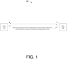
- FIG. 1 illustrates an example network environment 100 in which various solutions and schemes in accordance with the present disclosure may be implemented.
- FIG. 2 ⁇ FIG. 31 illustrate examples of implementation of various proposed schemes in network environment 100 in accordance with the present disclosure. The following description of various proposed schemes is provided with reference to FIG. 1 ⁇ FIG. 31 .
- network environment 100 may involve at least a station (STA) 110 communicating wirelessly with a STA 120.
- STA 110 and STA 120 may be an access point (AP) STA or, alternatively, either of STA 110 and STA 120 may function as a non-AP STA.
- STA 110 and STA 120 may be associated with a basic service set (BSS) in accordance with one or more IEEE 802.11 standards (e.g., IEEE 802.11be and future-developed standards).
- BSS basic service set
- IEEE 802.11 e.g., IEEE 802.11be and future-developed standards.
- Each of STA 110 and STA 120 may be configured to communicate with each other by utilizing the various proposed schemes of performance enhancement of RU duplication with predefined interleaving patterns in wireless communications in accordance with various proposed schemes described below.
- STA 110 and STA 120 may function as a "user" in the proposed schemes and examples described below. It is noteworthy that, while the various proposed schemes may be individually or separately described below, in actual implementations some or all of the proposed schemes may be utilized or otherwise implemented jointly. Of course, each of the proposed schemes may be utilized or otherwise implemented individually or separately.
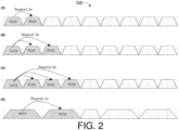
- FIG. 2 illustrates an example design 200 under a proposed scheme in accordance with the present disclosure.
- Design 200 may pertain to duplication of RU26 and RU52 with different numbers of repetition/duplication.
- Part (A) of FIG. 2 shows two times (2x) of duplication of a RU26.
- Part (B) of FIG. 2 shows three times (3x) of duplication of a RU26.
- Part (C) of FIG. 2 shows four times (4x) of duplication of a RU26.
- Part (D) of FIG. 2 shows two times (2x) of duplication of a RU52.
- a given RU e.g., RU26 or RU52
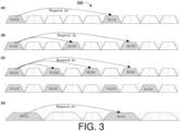
- FIG. 3 illustrates an example design 300 under a proposed scheme in accordance with the present disclosure.
- Design 300 may pertain to RU duplication with predefined interleaving patterns.
- RU duplication may be performed with predefined interleaving patterns.
- Part (A) of FIG. 3 shows two times (2x) of duplication of a RU26 with a predefined interleaving pattern.
- Part (B) of FIG. 3 shows three times (3x) of duplication of a RU26 with a predefined interleaving pattern.
- Part (C) of FIG. 3 shows four times (4x) of duplication of a RU26 with a predefined interleaving pattern.
- duplications of the RU are not adjacent to one another (e.g., not contiguous) in the frequency domain.
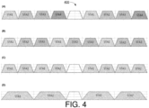
- FIG. 4 illustrates an example design 400 under a proposed scheme in accordance with the present disclosure.
- Design 400 may pertain to interleaved RU duplication for orthogonal frequency-division multiple-access (OFDMA) multi-users.
- Part (A) of FIG. 4 shows two times (2x) of duplication of respective RU26 for four users with a predefined interleaving pattern.
- Part (B) of FIG. 4 shows three times (3x) of duplication of respective RU26 for three users with a predefined interleaving pattern.
- Part (C) of FIG. 4 shows four times (4x) of duplication of respective RU26 for two users with a predefined interleaving pattern.
- Part (D) of FIG. 4 shows two times (2x) of duplication of respective RU52 for two users with a predefined interleaving pattern.
- FIG. 5 illustrates an example design 500 under a proposed scheme in accordance with the present disclosure.
- Design 500 may pertain to interleaved RU duplication for OFDMA multi-users.
- RU26 with four times (4x) of duplication may also be performed.
- Part (A) of FIG. 5 shows four times (4x) of duplication of respective RU26 for two users (e.g., STA1 and STA2) with a predefined interleaving pattern.
- FIG. 5 shows two times (2x) of duplication of respective RU52 for a first user (e.g., STA1) and four times (4x) of duplication of respective RU26 for a second user (e.g., STA2) with a predefined interleaving pattern.
- Part (C) of FIG. 5 shows two times (2x) of duplication of respective RU52 for a first user (e.g., STA1) and two times (2x) of duplication of respective RU26 for two users (e.g., STA2 and STA3) with a predefined interleaving pattern.
- FIG. 6 illustrates an example design 600 under a proposed scheme in accordance with the present disclosure.
- Design 600 may pertain to RU duplication with a predefined interleaving pattern.
- 6x an example of six times (6x) of duplication of a RU26 with a predefined interleaving pattern.
- interleaved RU duplication e.g., RU duplication or repetition with a predefined interleaving pattern
- a first option Option-1
- the same interleaving pattern may be kept with no change across OFDM symbols.
- Option-2 interleaving patterns may be periodically or alternatively switched over OFDM symbols.
- FIG. 7 illustrates an example scenario 700 under the proposed scheme with respect to Option-1.
- Part (A) of FIG. 7 shows an example of downlink (DL) transmission of an enhanced long range (ELR) physical-layer protocol data unit (PPDU) in which the preamble, ELR short training field (ELR-STF) and ELR long training field (ELR-LTF) are transmitted without any interleaving pattern, while transmission of RU(s) of an ELR data (ELR-DATA) is performed with RU duplication in the frequency domain using the same interleaving pattern across OFDM symbols of the ELR data.
- ELR enhanced long range
- PPDU physical-layer protocol data unit
- ELR-STF ELR short training field
- ELR-LTF ELR long training field
- FIG. 7 shows an example of uplink (UL) transmission of a trigger-based (TB) PPDU with the preamble transmitted without any interleaving pattern, while transmission of RUs of the ELR-STF, ELR-LTF and ELR-DATA is performed with RU duplication in the frequency domain using the same interleaving pattern across OFDM symbols of the ELR-STF, ELR-LTF and ELR data.
- UL uplink
- TB trigger-based
- FIG. 8 illustrates an example scenario 800 under the proposed scheme with respect to Option-2.
- FIG. 8 shows an example of DL transmission of an ELR PPDU with the preamble, ELR short training field (ELR-STF), ELR long training field (ELR-LTF) are transmitted without any interleaving pattern, while transmission of RU(s) of an ELR-DATA is performed with RU duplication in the frequency domain with interleaving patterns periodically or alternatively switched over OFDM symbols.
- ELR-STF ELR short training field
- ELR-LTF ELR long training field
- a first interleaving pattern (interleaving pattern-1) may be used in RU duplication for a first repetition of ELR-DATA
- a second interleaving pattern (interleaving pattern-2) may be used in RU duplication for a second repetition of ELR-DATA
- the first interleaving pattern (interleaving pattern-1) may be used in RU duplication for a third repetition of ELR-DATA
- the second interleaving pattern (interleaving pattern-2) may be used in RU duplication for a fourth repetition of ELR-DATA, and so on.
- Option-2 may be applicable in DL PPDU transmission scenarios but may not be applicable in other transmission scenarios.
- FIG. 9 illustrates an example design 900 under a proposed scheme in accordance with the present disclosure.
- Design 900 may pertain to a BW20 RU hierarchical structure and index.
- a RU26 may be duplicated nine times
- a RU52 may be duplicated four times
- a RU106 may be duplicated two times in the BW20.
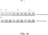
- FIG. 10 illustrates an example scenario 1000 under a proposed scheme in accordance with the present disclosure.
- Scenario 1000 may pertain to three times (3x) of duplication of a RU26 for three users (e.g., user-1, user-2 and user-3).
- Part (A) of FIG. 10 shows an example of RU duplication without interleaving for the three users.
- Part (B) of FIG. 10 shows an example of RU duplication with interleaving.
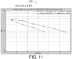
- FIG. 11 illustrates an example scenario 1100 under a proposed scheme in accordance with the present disclosure.
- Scenario 1100 may pertain to PER performance comparisons in simulation with respect to the 3x RU duplication of scenario 1000.
- the simulation utilized a modulation and coding scheme (MCS) of MCS0 with respect to a STA (e.g., STA 110 or STA 120) with one transmitter antenna and one receiver antenna (1T1R) using one spatial stream (1ss) in BW20 with RU26 duplication.
- MCS modulation and coding scheme
- the "RU242" of the FIG. 11 means that RU26 is duplicated within the tone range of 20MHz or RU242. This meaning can be applied to the figures hereafter, such as FIG. 12 to FIG. 17 , FIG. 19 to FIG. 24 and FIG. 26 to FIG.
- the upper curve in the graph represents a simulation result of RU duplication without interleaving.
- the lower curve in the graph represents a simulation result of RU duplication with interleaving.
- FIG. 12 illustrates an example scenario 1200 under a proposed scheme in accordance with the present disclosure.
- Scenario 1200 may pertain to PER performance comparisons in simulation with respect to the 3x RU duplication of scenario 1000.
- the simulation utilized MCS0 with respect to a STA (e.g., STA 110 or STA 120) with 1T1R using 1ss in BW20 with RU26 duplication.
- the curve to the right in the graph represents a simulation result of RU duplication without interleaving.
- the curve to the left in the graph represents a simulation result of RU duplication with interleaving.
- FIG. 13 illustrates an example scenario 1300 under a proposed scheme in accordance with the present disclosure.
- Scenario 1300 may pertain to PER performance comparisons in simulation with respect to the 3x RU duplication of scenario 1000.
- the simulation utilized MCS0 with respect to a STA (e.g., STA 110 or STA 120) with 1T1R using 1ss in BW20 with RU26 duplication.
- the curve to the right in the graph represents a simulation result of RU duplication without interleaving.
- the curve to the left in the graph represents a simulation result of RU duplication with interleaving.
- FIG. 14 illustrates an example scenario 1400 under a proposed scheme in accordance with the present disclosure.
- Scenario 1400 may pertain to PER performance comparisons in simulation with respect to the 3x RU duplication of scenario 1000.
- the simulation utilized MCS0 with respect to a STA (e.g., STA 110 or STA 120) with one transmitter antenna and two receiver antennas (1T2R) using 1ss in BW20 with RU26 duplication.
- the curve to the right in the graph represents a simulation result of RU duplication without interleaving.
- the curve to the left in the graph represents a simulation result of RU duplication with interleaving.
- FIG. 15 illustrates an example scenario 1500 under a proposed scheme in accordance with the present disclosure.
- Scenario 1500 may pertain to PER performance comparisons in simulation with respect to the 3x RU duplication of scenario 1000.
- the simulation utilized MCS15 with respect to a STA (e.g., STA 110 or STA 120) with 1T2R using 1ss in BW20 with RU26 duplication.
- the curve to the right in the graph represents a simulation result of RU duplication without interleaving.
- the curve to the left in the graph represents a simulation result of RU duplication with interleaving.
- FIG. 16 illustrates an example scenario 1600 under a proposed scheme in accordance with the present disclosure.
- Scenario 1600 may pertain to PER performance comparisons in simulation with respect to the 3x RU duplication of scenario 1000.
- the simulation utilized MCS15 with respect to a STA (e.g., STA 110 or STA 120) with one transmitter antenna and four receiver antennas (1T4R) using 1ss in BW20 with RU26 duplication.
- the curve to the right in the graph represents a simulation result of RU duplication without interleaving.
- the curve to the left in the graph represents a simulation result of RU duplication with interleaving.
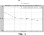
- FIG. 17 illustrates an example scenario 1700 under a proposed scheme in accordance with the present disclosure.
- Scenario 1700 may pertain to PER performance comparisons in simulation with respect to the 3x RU duplication of scenario 1000.
- the simulation utilized MCS15 with respect to a STA (e.g., STA 110 or STA 120) with 1T4R using 1ss in BW20 with RU26 duplication.
- the curve to the right in the graph represents a simulation result of RU duplication without interleaving.
- the curve to the left in the graph represents a simulation result of RU duplication with interleaving.
- FIG. 18 illustrates an example scenario 1800 under a proposed scheme in accordance with the present disclosure.
- Scenario 1800 may pertain to four times (4x) of duplication of a RU26 for two users (e.g., user-1 and user-2).
- Part (A) of FIG. 18 shows an example of RU duplication without interleaving for the three users.
- Part (B) of FIG. 18 shows an example of RU duplication with interleaving.
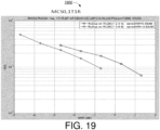
- FIG. 19 illustrates an example scenario 1900 under a proposed scheme in accordance with the present disclosure.
- Scenario 1900 may pertain to PER performance comparisons in simulation with respect to the 4x RU duplication of scenario 1800.
- the simulation utilized MCS0 with respect to a STA (e.g., STA 110 or STA 120) with 1T1R using 1ss in BW20 with RU26 duplication.
- the curve to the right in the graph represents a simulation result of RU duplication without interleaving.
- the curve to the left in the graph represents a simulation result of RU duplication with interleaving.
- FIG. 20 illustrates an example scenario 2000 under a proposed scheme in accordance with the present disclosure.
- Scenario 2000 may pertain to PER performance comparisons in simulation with respect to the 4x RU duplication of scenario 1800.
- the simulation utilized MCS0 with respect to a STA (e.g., STA 110 or STA 120) with 1T1R using 1ss in BW20 with RU26 duplication.
- the curve to the right in the graph represents a simulation result of RU duplication without interleaving.
- the curve to the left in the graph represents a simulation result of RU duplication with interleaving.
- FIG. 21 illustrates an example scenario 2100 under a proposed scheme in accordance with the present disclosure.
- Scenario 2100 may pertain to PER performance comparisons in simulation with respect to the 4x RU duplication of scenario 1800.
- the simulation utilized MCS0 with respect to a STA (e.g., STA 110 or STA 120) with 1T2R using 1ss in BW20 with RU26 duplication.
- the curve to the right in the graph represents a simulation result of RU duplication without interleaving.
- the curve to the left in the graph represents a simulation result of RU duplication with interleaving.
- FIG. 22 illustrates an example scenario 2200 under a proposed scheme in accordance with the present disclosure.
- Scenario 2200 may pertain to PER performance comparisons in simulation with respect to the 4x RU duplication of scenario 1800.
- the simulation utilized MCS0 with respect to a STA (e.g., STA 110 or STA 120) with 1T2R using 1ss in BW20 with RU26 duplication.
- the curve to the right in the graph represents a simulation result of RU duplication without interleaving.
- the curve to the left in the graph represents a simulation result of RU duplication with interleaving.
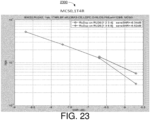
- FIG. 23 illustrates an example scenario 2300 under a proposed scheme in accordance with the present disclosure.
- Scenario 2300 may pertain to PER performance comparisons in simulation with respect to the 4x RU duplication of scenario 1800.
- the simulation utilized MCS0 with respect to a STA (e.g., STA 110 or STA 120) with 1T4R using 1ss in BW20 with RU26 duplication.
- the curve to the right in the graph represents a simulation result of RU duplication without interleaving.
- the curve to the left in the graph represents a simulation result of RU duplication with interleaving.
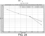
- FIG. 24 illustrates an example scenario 2400 under a proposed scheme in accordance with the present disclosure.
- Scenario 2400 may pertain to PER performance comparisons in simulation with respect to the 4x RU duplication of scenario 1800.
- the simulation utilized MCS0 with respect to a STA (e.g., STA 110 or STA 120) with 1T4R using 1ss in BW20 with RU26 duplication.
- the curve to the right in the graph represents a simulation result of RU duplication without interleaving.
- the curve to the left in the graph represents a simulation result of RU duplication with interleaving.
- FIG. 25 illustrates an example scenario 2500 under a proposed scheme in accordance with the present disclosure.
- Scenario 2500 may pertain to two times (2x) of duplication of a RU52 for two users (e.g., user-1 and user-2).
- Part (A) of FIG. 25 shows an example of RU duplication without interleaving for the three users.
- Part (B) of FIG. 25 shows an example of RU duplication with interleaving.
- FIG. 26 illustrates an example scenario 2600 under a proposed scheme in accordance with the present disclosure.
- Scenario 2600 may pertain to PER performance comparisons in simulation with respect to the 2x RU duplication of scenario 2500.
- the simulation utilized MCS0 with respect to a STA (e.g., STA 110 or STA 120) with 1T1R using 1ss in BW20 with RU52 duplication.
- the curve to the right in the graph represents a simulation result of RU duplication without interleaving.
- the curve to the left in the graph represents a simulation result of RU duplication with interleaving.
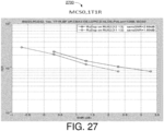
- FIG. 27 illustrates an example scenario 2700 under a proposed scheme in accordance with the present disclosure.
- Scenario 2700 may pertain to PER performance comparisons in simulation with respect to the 2x RU duplication of scenario 2500.
- the simulation utilized MCS0 with respect to a STA (e.g., STA 110 or STA 120) with 1T1R using 1ss in BW20 with RU52 duplication.
- the curve to the right in the graph represents a simulation result of RU duplication without interleaving.
- the curve to the left in the graph represents a simulation result of RU duplication with interleaving.
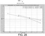
- FIG. 28 illustrates an example scenario 2800 under a proposed scheme in accordance with the present disclosure with respect to the 2x RU duplication of scenario 2500.
- Scenario 2800 may pertain to PER performance comparisons in simulation.
- the simulation utilized MCS0 with respect to a STA (e.g., STA 110 or STA 120) with 1T2R using 1ss in BW20 with RU52 duplication.
- the curve to the right in the graph represents a simulation result of RU duplication without interleaving.
- the curve to the left in the graph represents a simulation result of RU duplication with interleaving.
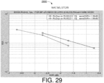
- FIG. 29 illustrates an example scenario 2900 under a proposed scheme in accordance with the present disclosure.
- Scenario 2900 may pertain to PER performance comparisons in simulation with respect to the 2x RU duplication of scenario 2500.
- the simulation utilized MCS0 with respect to a STA (e.g., STA 110 or STA 120) with 1T2R using 1ss in BW20 with RU52 duplication.
- the curve to the right in the graph represents a simulation result of RU duplication without interleaving.
- the curve to the left in the graph represents a simulation result of RU duplication with interleaving.
- FIG. 30 illustrates an example system 3000 having at least an example apparatus 3010 and an example apparatus 3020 in accordance with an implementation of the present disclosure.
- apparatus 3010 and apparatus 3020 may perform various functions to implement schemes, techniques, processes and methods described herein pertaining to performance enhancement of RU duplication with predefined interleaving patterns in wireless communications, including the various schemes described above with respect to various proposed designs, concepts, schemes, systems and methods described above as well as processes described below.
- apparatus 3010 may be implemented in STA 110 and apparatus 3020 may be implemented in STA 120, or vice versa.
- Each of apparatus 3010 and apparatus 3020 may be a part of an electronic apparatus, which may be a non-AP STA or an AP STA, such as a portable or mobile apparatus, a wearable apparatus, a wireless communication apparatus or a computing apparatus.
- an electronic apparatus which may be a non-AP STA or an AP STA, such as a portable or mobile apparatus, a wearable apparatus, a wireless communication apparatus or a computing apparatus.
- each of apparatus 3010 and apparatus 3020 may be implemented in a smartphone, a smart watch, a personal digital assistant, a digital camera, or a computing equipment such as a tablet computer, a laptop computer or a notebook computer.
- Each of apparatus 3010 and apparatus 3020 may also be a part of a machine type apparatus, which may be an IoT apparatus such as an immobile or a stationary apparatus, a home apparatus, a wire communication apparatus or a computing apparatus.
- each of apparatus 3010 and apparatus 3020 may be implemented in a smart thermostat, a smart fridge, a smart door lock, a wireless speaker or a home control center.
- apparatus 3010 and/or apparatus 3020 may be implemented in a network node, such as an AP in a WLAN.
- each of apparatus 3010 and apparatus 3020 may be implemented in the form of one or more integrated-circuit (IC) chips such as, for example and without limitation, one or more single-core processors, one or more multi-core processors, one or more reduced-instruction set computing (RISC) processors, or one or more complex-instruction-set-computing (CISC) processors.
- IC integrated-circuit
- RISC reduced-instruction set computing
- CISC complex-instruction-set-computing
- each of apparatus 3010 and apparatus 3020 may be implemented in or as a STA or an AP.
- Each of apparatus 3010 and apparatus 3020 may include at least some of those components shown in FIG. 30 such as a processor 3012 and a processor 3022, respectively, for example.
- Each of apparatus 3010 and apparatus 3020 may further include one or more other components not pertinent to the proposed scheme of the present disclosure (e.g., internal power supply, display device and/or user interface device), and, thus, such component(s) of apparatus 3010 and apparatus 3020 are neither shown in FIG. 30 nor described below in the interest of simplicity and brevity.
- other components e.g., internal power supply, display device and/or user interface device
- each of processor 3012 and processor 3022 may be implemented in the form of one or more single-core processors, one or more multi-core processors, one or more RISC processors or one or more CISC processors. That is, even though a singular term "a processor" is used herein to refer to processor 3012 and processor 3022, each of processor 3012 and processor 3022 may include multiple processors in some implementations and a single processor in other implementations in accordance with the present disclosure.
- each of processor 3012 and processor 3022 may be implemented in the form of hardware (and, optionally, firmware) with electronic components including, for example and without limitation, one or more transistors, one or more diodes, one or more capacitors, one or more resistors, one or more inductors, one or more memristors and/or one or more varactors that are configured and arranged to achieve specific purposes in accordance with the present disclosure.
- each of processor 3012 and processor 3022 is a special-purpose machine specifically designed, arranged and configured to perform specific tasks including those pertaining to performance enhancement of RU duplication with predefined interleaving patterns in wireless communications in accordance with various implementations of the present disclosure.
- apparatus 3010 may also include a transceiver 3016 coupled to processor 3012.
- Transceiver 3016 may include a transmitter capable of wirelessly transmitting and a receiver capable of wirelessly receiving data.
- apparatus 3020 may also include a transceiver 3026 coupled to processor 3022.
- Transceiver 3026 may include a transmitter capable of wirelessly transmitting and a receiver capable of wirelessly receiving data.
- transceiver 3016 and transceiver 3026 are illustrated as being external to and separate from processor 3012 and processor 3022, respectively, in some implementations, transceiver 3016 may be an integral part of processor 3012 as a system on chip (SoC), and transceiver 3026 may be an integral part of processor 3022 as a SoC.
- SoC system on chip
- apparatus 3010 may further include a memory 3014 coupled to processor 3012 and capable of being accessed by processor 3012 and storing data therein.
- apparatus 3020 may further include a memory 3024 coupled to processor 3022 and capable of being accessed by processor 3022 and storing data therein.
- RAM random-access memory
- DRAM dynamic RAM
- SRAM static RAM
- T-RAM thyristor RAM
- Z-RAM zero-capacitor RAM
- each of memory 3014 and memory 3024 may include a type of read-only memory (ROM) such as mask ROM, programmable ROM (PROM), erasable programmable ROM (EPROM) and/or electrically erasable programmable ROM (EEPROM).
- ROM read-only memory
- PROM programmable ROM
- EPROM erasable programmable ROM
- EEPROM electrically erasable programmable ROM
- each of memory 3014 and memory 3024 may include a type of non-volatile random-access memory (NVRAM) such as flash memory, solid-state memory, ferroelectric RAM (FeRAM), magnetoresistive RAM (MRAM) and/or phase-change memory.
- NVRAM non-volatile random-access memory
- Each of apparatus 3010 and apparatus 3020 may be a communication entity capable of communicating with each other using various proposed schemes in accordance with the present disclosure.
- a description of capabilities of apparatus 3010, as STA 110, and apparatus 3020, as STA 120, is provided below in the context of example process 3100.
- apparatus 3020 may be applied to apparatus 3010 although a detailed description thereof is not provided solely in the interest of brevity.
- example implementations described below are provided in the context of WLAN, the same may be implemented in other types of networks.
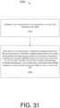
- FIG. 31 illustrates an example process 3100 in accordance with an implementation of the present disclosure.
- Process 3100 may represent an aspect of implementing various proposed designs, concepts, schemes, systems and methods described above. More specifically, process 3100 may represent an aspect of the proposed concepts and schemes pertaining to performance enhancement of RU duplication with predefined interleaving patterns in wireless communications in accordance with the present disclosure.
- Process 3100 may include one or more operations, actions, or functions as illustrated by one or more of blocks 3110 and 3120. Although illustrated as discrete blocks, various blocks of process 3100 may be divided into additional blocks, combined into fewer blocks, or eliminated, depending on the desired implementation. Moreover, the blocks/sub-blocks of process 3100 may be executed in the order shown in FIG. 31 or, alternatively, in a different order.
- Process 3100 may be implemented by or in apparatus 3010 and apparatus 3020 as well as any variations thereof. Solely for illustrative purposes and without limiting the scope, process 3100 is described below in the context of apparatus 3010 implemented in or as STA 110 functioning as a non-AP STA and apparatus 3020 implemented in or as STA 120 functioning as an AP STA of a wireless network such as a WLAN in network environment 100 in accordance with one or more of IEEE 802.11 standards. Process 3100 may begin at block 3110.
- process 3100 may involve processor 3012 of apparatus 3010 generating at least one RU. Process 3100 may proceed from 3110 to 3120.
- process 3100 may involve processor 3012 performing, via transceiver 3016, a wireless communication (e.g., with apparatus 3020) with RU duplication in a frequency domain using either: (a) a same interleaving pattern applied across OFDM symbols of each duplicated RU of the at least one RU; or (b) two or more interleaving patterns periodically or alternatively switched over OFDM symbols of two or more duplicated RUs of the at least one RU.
- a wireless communication e.g., with apparatus 3020
- RU duplication in a frequency domain using either: (a) a same interleaving pattern applied across OFDM symbols of each duplicated RU of the at least one RU; or (b) two or more interleaving patterns periodically or alternatively switched over OFDM symbols of two or more duplicated RUs of the at least one RU.
- the at least one RU may include a plurality of RUs of different sizes.
- process 3100 may involve processor 3012 duplicating the plurality of RUs of different sizes.
- the at least one RU may include a plurality of RUs of a same size.
- process 3100 may involve processor 3012 duplicating the plurality of RUs different number of times such that a first RU of the plurality of RUs is duplicated N times and a second RU of the plurality of RUs is duplicated M times, with N not equal to M.
- N may be either equal or not equal to M.
- the at least one RU may include a plurality of RUs of different sizes.
- process 3100 may involve processor 3012 duplicating the plurality of RUs different number of times such that a first RU of the plurality of RUs of a first size is duplicated N times and a second RU of the plurality of RUs of a second size is duplicated M times, with N not equal to M and with the first size not equal to the second size.
- N may be either equal or not equal to M.
- the at least one RU may include a 26-tone RU (RU26).
- process 3100 may involve processor 3012 duplicating the RU26 three times (3x) for each of one or more users.
- process 3100 may involve processor 3012 duplicating the RU26 four times (4x) for each of one or more users.
- process 3100 may involve processor 3012 performing a DL communication of an ELR PPDU with RU duplication using the same interleaving pattern such that a preamble, an ELR-STF and an ELR-LTF of the ELR PPDU are transmitted without any interleaving pattern while transmission of one or more RUs of the at least one RU in an ELR-DATA is performed with RU duplication using the same interleaving pattern.
- process 3100 may involve processor 3012 performing an UL communication of a TB ELR PPDU with RU duplication using the same interleaving pattern such that a preamble of the TB ELR PPDU is transmitted without any interleaving pattern while transmission of one or more RUs of the at least one RU in an ELR-STF, an ELR-LTF and an ELR-DATA is performed with RU duplication using the same interleaving pattern.
- process 3100 may involve processor 3012 performing a DL communication of an ELR PPDU with RU duplication using the two or more interleaving patterns that are periodically or alternatively switched such that a preamble, an ELR-STF and an ELR-LTF of the ELR PPDU are transmitted without any interleaving pattern while transmission of two or more RUs of the at least one RU in an ELR-DATA is performed with RU duplication using the interleaving patterns periodically or alternatively switched in the frequency domain.
- process 3100 may involve processor 3012 duplicating the at least one RU such that duplications of the at least one RU are not adjacent to one another in the frequency domain.
- any two components so associated can also be viewed as being “operably connected”, or “operably coupled”, to each other to achieve the desired functionality, and any two components capable of being so associated can also be viewed as being “operably couplable”, to each other to achieve the desired functionality.
- operably couplable include but are not limited to physically mateable and/or physically interacting components and/or wirelessly interactable and/or wirelessly interacting components and/or logically interacting and/or logically interactable components.
Landscapes
- Engineering & Computer Science (AREA)
- Signal Processing (AREA)
- Computer Networks & Wireless Communication (AREA)
- Mobile Radio Communication Systems (AREA)
- Radio Transmission System (AREA)
Applications Claiming Priority (2)
| Application Number | Priority Date | Filing Date | Title |
|---|---|---|---|
| US202263376123P | 2022-09-19 | 2022-09-19 | |
| US18/369,068 US20240097820A1 (en) | 2022-09-19 | 2023-09-15 | Performance Enhancement Of RU Duplication With Predefined Interleaving Patterns In Wireless Communications |
Publications (2)
| Publication Number | Publication Date |
|---|---|
| EP4340286A2 true EP4340286A2 (de) | 2024-03-20 |
| EP4340286A3 EP4340286A3 (de) | 2024-04-10 |
Family
ID=88093470
Family Applications (1)
| Application Number | Title | Priority Date | Filing Date |
|---|---|---|---|
| EP23198029.3A Pending EP4340286A3 (de) | 2022-09-19 | 2023-09-18 | Leistungsverbesserung einer ru-duplizierung mit vordefinierten verschachtelungsmustern in der drahtlosen kommunikation |
Country Status (3)
| Country | Link |
|---|---|
| US (1) | US20240097820A1 (de) |
| EP (1) | EP4340286A3 (de) |
| TW (1) | TW202415039A (de) |
Families Citing this family (4)
| Publication number | Priority date | Publication date | Assignee | Title |
|---|---|---|---|---|
| WO2025228435A1 (en) * | 2024-05-03 | 2025-11-06 | Mediatek Inc. | Short training field and long training field transmission methods for enhanced long range wi-fi |
| WO2025228418A1 (en) * | 2024-05-03 | 2025-11-06 | Mediatek Inc. | Data transmission methods for enhanced long range wi-fi |
| WO2025247375A1 (en) * | 2024-05-31 | 2025-12-04 | Mediatek Inc. | Signaling field designs for next-generation enhanced long range wi-fi |
| WO2025258881A1 (ko) * | 2024-06-14 | 2025-12-18 | 엘지전자 주식회사 | 장거리 통신을 위한 트레이닝 신호의 구성 |
Family Cites Families (12)
| Publication number | Priority date | Publication date | Assignee | Title |
|---|---|---|---|---|
| US9246635B2 (en) * | 2013-11-11 | 2016-01-26 | Lg Electronics Inc. | Apparatus for transmitting broadcast signals, apparatus for receiving broadcast signals, method for transmitting broadcast signals and method for receiving broadcast signals |
| GB201410025D0 (en) * | 2014-06-05 | 2014-07-16 | Ocado Ltd | Systems and methods for communication |
| US10355812B2 (en) * | 2016-02-05 | 2019-07-16 | Samsung Electronics Co., Ltd. | Multiple access method, and corresponding transmission method, receiver and transmitter |
| KR102164967B1 (ko) * | 2017-01-06 | 2020-10-13 | 한국전자통신연구원 | 통신 시스템에서 제어 채널의 송수신 방법 및 장치 |
| CN110463122B (zh) * | 2017-07-12 | 2022-04-12 | Lg 电子株式会社 | 在tdd特殊子帧上接收下行链路物理信道的方法和nb-iot设备 |
| US11387937B2 (en) * | 2019-08-07 | 2022-07-12 | Huawei Technologies Co., Ltd. | Preamble with detectable WLAN version identification |
| US12489570B2 (en) * | 2020-03-13 | 2025-12-02 | Qualcomm Incorporated | Distributed tone mapping for power spectral density (PSD) limits |
| US11882062B2 (en) * | 2020-06-16 | 2024-01-23 | Nxp Usa, Inc. | Method and apparatus for wireless communications |
| CN115997372B (zh) * | 2020-07-02 | 2025-06-24 | Lg电子株式会社 | 在无线局域网系统中接收其中数据被复制并应用相位旋转的ppdu的方法和装置 |
| US11870735B2 (en) * | 2020-07-28 | 2024-01-09 | Mediatek Singapore Pte. Ltd. | Simplification for distributed-tone resource units in 6GHz low-power indoor systems |
| WO2023041773A1 (en) * | 2021-09-20 | 2023-03-23 | Sony Group Corporation | First and second communication devices and methods |
| US20240015059A1 (en) * | 2022-07-07 | 2024-01-11 | Nxp Usa, Inc. | Method and system for range extension in wireless communication |
-
2023
- 2023-09-15 US US18/369,068 patent/US20240097820A1/en active Pending
- 2023-09-18 EP EP23198029.3A patent/EP4340286A3/de active Pending
- 2023-09-19 TW TW112135721A patent/TW202415039A/zh unknown
Also Published As
| Publication number | Publication date |
|---|---|
| TW202415039A (zh) | 2024-04-01 |
| US20240097820A1 (en) | 2024-03-21 |
| EP4340286A3 (de) | 2024-04-10 |
Similar Documents
| Publication | Publication Date | Title |
|---|---|---|
| EP3945693B1 (de) | Designvereinfachung für ressourceneinheiten mit verteiltem ton in 6-hgz-innenraumsystemen mit niedriger leistungsaufnahme | |
| US12160383B2 (en) | EHT-STF transmission for distributed-tone resource units in 6GHz low-power indoor systems | |
| EP4340286A2 (de) | Leistungsverbesserung einer ru-duplizierung mit vordefinierten verschachtelungsmustern in der drahtlosen kommunikation | |
| EP4047894A1 (de) | Eht-ltf-sequenzentwurf für verteilte ton-ressourceneinheiten mit papr-reduktion | |
| US11997523B2 (en) | Efficient trigger-based multi-user uplink transmissions in wireless local area networks | |
| EP4319071A1 (de) | Papr-reduktion zur duplizierung einer ressourceneinheit und tonwiederholung | |
| US20250310162A1 (en) | Wide bandwidth resource unit tone plan designs for next-generation wlan | |
| EP4156589A1 (de) | Globale csd-indexzuweisung für übertragungen von ressourceneinheiten mit verteilten tönen | |
| EP4588295A1 (de) | 4x-ltf-sequenzdesign für breite bandbreiten in der drahtlosen kommunikation | |
| EP4319028A1 (de) | Übertragungsverfahren zur verteilung von ressourceneinheiten und tonwiederholung für erweiterte fernkommunikation | |
| EP4340266A1 (de) | Parameterdesigns physikalischer schichten zur ermöglichung von ru-duplikation und tonwiederholung für wlan der nächsten generation | |
| EP4340309A1 (de) | Stf-sequenzdesign für breite bandbreiten in der drahtlosen kommunikation | |
| EP4344117A1 (de) | Entwürfe für ressourceneinheiten mit verteilten tönen für breitbandige160 mhz in der drahtlosen kommunikation | |
| EP4239932A1 (de) | Skalierbare wellenform- und numerologieentwürfe für wlan der nächsten generation im 60ghz-band | |
| US20230299931A1 (en) | Channelization Of 60GHz Band For Next-Generation WLAN | |
| WO2024165047A1 (en) | Time domain symbol repetition for enhanced long range wi-fi | |
| WO2023237111A1 (en) | Designs of multi-ru in wider bandwidth ppdu for next-generation wlan | |
| WO2024251277A1 (en) | Multiple mru transmission methods for next-generation wlan systems | |
| WO2025185610A1 (en) | Enhanced long range transmission for next-generation wi-fi in wireless communications | |
| WO2024160248A1 (en) | Sub-resource unit based adaptive modulation schemes in wireless communications | |
| WO2025228418A1 (en) | Data transmission methods for enhanced long range wi-fi | |
| EP4346150A1 (de) | Betrieb einer ressourceneinheit mit verteilten tönen für breitbandbreitband in wlan-systemen der nächsten generation | |
| US20250080295A1 (en) | Distributed-Tone Resource Unit Based Enhanced Long Range Communication Schemes In WLAN | |
| WO2026046200A1 (en) | Coding and rate matching designs for uhr enhanced long range wi-fi | |
| WO2023237037A1 (en) | Wide bandwidth resource unit tone plan designs for next-generation wlan |
Legal Events
| Date | Code | Title | Description |
|---|---|---|---|
| PUAI | Public reference made under article 153(3) epc to a published international application that has entered the european phase |
Free format text: ORIGINAL CODE: 0009012 |
|
| STAA | Information on the status of an ep patent application or granted ep patent |
Free format text: STATUS: THE APPLICATION HAS BEEN PUBLISHED |
|
| PUAL | Search report despatched |
Free format text: ORIGINAL CODE: 0009013 |
|
| AK | Designated contracting states |
Kind code of ref document: A2 Designated state(s): AL AT BE BG CH CY CZ DE DK EE ES FI FR GB GR HR HU IE IS IT LI LT LU LV MC ME MK MT NL NO PL PT RO RS SE SI SK SM TR |
|
| AK | Designated contracting states |
Kind code of ref document: A3 Designated state(s): AL AT BE BG CH CY CZ DE DK EE ES FI FR GB GR HR HU IE IS IT LI LT LU LV MC ME MK MT NL NO PL PT RO RS SE SI SK SM TR |
|
| RIC1 | Information provided on ipc code assigned before grant |
Ipc: H04W 84/12 20090101ALI20240305BHEP Ipc: H04W 72/04 20230101ALI20240305BHEP Ipc: H04L 5/00 20060101AFI20240305BHEP |
|
| STAA | Information on the status of an ep patent application or granted ep patent |
Free format text: STATUS: REQUEST FOR EXAMINATION WAS MADE |
|
| 17P | Request for examination filed |
Effective date: 20240702 |
|
| RBV | Designated contracting states (corrected) |
Designated state(s): AL AT BE BG CH CY CZ DE DK EE ES FI FR GB GR HR HU IE IS IT LI LT LU LV MC ME MK MT NL NO PL PT RO RS SE SI SK SM TR |