EP4340773B1 - Intraorale scannerhülse - Google Patents
Intraorale scannerhülse Download PDFInfo
- Publication number
- EP4340773B1 EP4340773B1 EP22729932.8A EP22729932A EP4340773B1 EP 4340773 B1 EP4340773 B1 EP 4340773B1 EP 22729932 A EP22729932 A EP 22729932A EP 4340773 B1 EP4340773 B1 EP 4340773B1
- Authority
- EP
- European Patent Office
- Prior art keywords
- sleeve
- transparent cover
- window opening
- window
- hollow body
- Prior art date
- Legal status (The legal status is an assumption and is not a legal conclusion. Google has not performed a legal analysis and makes no representation as to the accuracy of the status listed.)
- Active
Links
Images







Classifications
-
- A—HUMAN NECESSITIES
- A61—MEDICAL OR VETERINARY SCIENCE; HYGIENE
- A61C—DENTISTRY; APPARATUS OR METHODS FOR ORAL OR DENTAL HYGIENE
- A61C9/00—Impression cups, i.e. impression trays; Impression methods
- A61C9/004—Means or methods for taking digitized impressions
- A61C9/0046—Data acquisition means or methods
- A61C9/0053—Optical means or methods, e.g. scanning the teeth by a laser or light beam
-
- A—HUMAN NECESSITIES
- A61—MEDICAL OR VETERINARY SCIENCE; HYGIENE
- A61B—DIAGNOSIS; SURGERY; IDENTIFICATION
- A61B1/00—Instruments for performing medical examinations of the interior of cavities or tubes of the body by visual or photographical inspection, e.g. endoscopes; Illuminating arrangements therefor
- A61B1/00142—Instruments for performing medical examinations of the interior of cavities or tubes of the body by visual or photographical inspection, e.g. endoscopes; Illuminating arrangements therefor with means for preventing contamination, e.g. by using a sanitary sheath
-
- A—HUMAN NECESSITIES
- A61—MEDICAL OR VETERINARY SCIENCE; HYGIENE
- A61B—DIAGNOSIS; SURGERY; IDENTIFICATION
- A61B1/00—Instruments for performing medical examinations of the interior of cavities or tubes of the body by visual or photographical inspection, e.g. endoscopes; Illuminating arrangements therefor
- A61B1/24—Instruments for performing medical examinations of the interior of cavities or tubes of the body by visual or photographical inspection, e.g. endoscopes; Illuminating arrangements therefor for the mouth, i.e. stomatoscopes, e.g. with tongue depressors; Instruments for opening or keeping open the mouth
Definitions
- the apparatuses and methods described herein may relate to protective sleeves for optical scanners, and particularly for intraoral scanner that may be useful in scanning the intraoral cavity.
- An intraoral scanner may provide such imaging.
- an intraoral scanner may include a hand-held sensing component for scanning within the patient's oral cavity.
- the hand-held component may be referred to as a wand, and may include one or more windows for transmitting and/or receiving light to form images from within the patient's oral cavity.
- a protective element referred to herein as a sleeve or as a protective sleeve, may be used with the wand.
- the sleeve can act as barrier between the wand and the patient to protect the patient from cross-contamination.
- the sleeve may be removable from the wand so that the sleeve can be replaced before using the wand with the next patient.
- the optical qualities and the shape and size of the sleeves may affect the performance of the intraoral scanner.
- the barrier device can include a cover that has an integrated window for passing optical signals between the scanning device and an external environment.
- the cover includes multiple engagement features configured to engage with corresponding engagement features of the scanner device.
- the cover can include a sleeve that covers a handle portion of the scanning device to prevent contamination of the handle from a user's hand or glove.
- Described herein are methods and apparatuses, including protective sleeves, systems including protective sleeves, and methods of using them to address these problems and that may enhance the safety and functionality of intraoral scanners.
- sleeves for an intraoral scanner that are configured to securely couple with an intraoral scanner wand.
- These sleeves may be adapted as a unitary (single) body and may include one or more internal structures that are integrally formed with the unitary body on the inside of the sleeve to guide and direct the distal end of a wand of an intraoral scanner into the sleeve securely without risking damage to the wand of the intraoral scanner and/or the window (e.g., glass cover window) of the sleeve.
- sleeves for use with an intraoral scanner that include: a sleeve body configured to fit onto a wand of an intraoral scanner; a window through the sleeve body formed of a transparent material (e.g., glass or equivalent material such as a transparent plastic), wherein the window is configured to align with a field of view of the intraoral scanner.
- the window e.g., glass insert
- the window may include one or more identifiers configured to impinge into the field of view of the intraoral scanner when the sleeve is attached to the intraoral scanner.
- the identifier may include a projection or protrusion into the window opening.
- the identifier may identify one or more of: the identity of the sleeve and the use status of the sleeve (e.g., sleeve is on/not on).
- the sleeve body may be configured to be worn over the wand, and/or attached to the end of the wand.
- an intraoral scanning system may include: an intraoral scanner comprising a wand having a transmission window for transmitting and/or receiving light to form images from within the patient's oral cavity and a processor, the transmission window having field of view; and a sleeve configured to be worn on the wand, the sleeve comprising a sleeve body, a sleeve window through the sleeve body, the sleeve window configured to align with the transmission window.
- any of the sleeves described herein may include one or more internal guiding structures (e.g., ramps, slides, etc.) within the inside of the sleeve for guiding and/or securing the wand of the intraoral scanner in the sleeve to prevent damage to the wand and/or to prevent damage to the sleeve, and in particular the window (transparent, e.g., glass, cover of the sleeve) through which imaging may be performed.
- This internal guiding structure e.g., ramp
- This internal guiding structure may be formed integrally with (e.g., injection molded as part of) the inside of the sleeve, and of the same material as the sleeve.
- sleeves for intraoral scanners may include: an elongate and hollow body having a distal end and a proximal end, wherein the distal end is tapered and closed, and the proximal end is open to receive an intraoral scanner; a window opening on a lateral side of the distal end; a transparent (e.g., glass, clear plastic, etc.) cover over the window opening; and an internal guiding structure (e.g., ramp) formed integrally with the elongate and hollow body, wherein the ramp is positioned within the hollow body proximal to the window opening, and configured to guide a distal end of the intraoral scanner away from the window opening as the intraoral scanner is inserted into the sleeve.
- an internal guiding structure e.g., ramp
- the internal guiding structure comprises a plurality of ribs or fins extending in a proximal to distal direction within the hollow body.
- the ribs or fins may have a triangular shape (e.g., having a more acute angle, e.g., between 5 degrees and 45 degrees, proximally and a less acute angle, e.g., between 25 degrees and 90 degrees, distally.
- the internal guiding structure may be arranged within 10 cm of the window opening, on the same side of the hollow body as the window opening, and proximal to the hollow opening, so as to guide the distal end of a wand into the correct position and alignment with the window opening, for imaging through the transparent window.
- any of these apparatuses may include a foam at least partially circumferentially around the window opening within the hollow body.
- the transparent cover may be secured against the foam.
- the form may be a compressible foam.
- the foam may seal the transparent window against the window opening of the sleeve.
- any of the sleeves described herein may include one or more projections from a periphery of the window into the window opening configured to impinge into a field of view of the intraoral scanner when the intraoral scanner is engaged with the sleeve.
- These one or more projections may be detected by the intraoral scanner, and their shape and/or position may be detected by the intraoral scanner automatically or manually to identify the identity (e.g., make, model, batch, etc.) of the sleeve and/or that the sleeve has attached over the wand; in some examples the projection or other marking on the sleeve may be detected and used to confirm that the sleeve has been correctly or fully coupled to the wand.
- any of the sleeves described herein may include an extension at the proximal end of the rigid portion of the sleeve.
- the sleeve's elongate and hollow body may be formed of a proximal region including a rigid or semi-rigid body.
- a softer, more flexible extension region may be attached and/or may extend from the proximal end of the sleeve.
- the sleeve may include an extension extending from the proximal end of the elongate and hollow body.
- the sleeve extension is welded (e.g., laser welded) to the sleeve.
- the material forming the sleeve extension may be the same as the material of the sleeve (e.g., polyethylene).
- the sleeve extension may be configured to invert over itself when pulled distally, such as when removing the sleeve from over the wand.
- the sleeve extension may prevent contamination by inverting back over itself (trapping any contaminated portions within the sleeve).
- the sleeve may be formed of a polymeric material, such as, for example, a polyethylene material.
- any of these sleeves may include an adhesive seal around the window opening sealing the transparent cover to the window opening.
- the adhesive seal may be formed of a liquid adhesive that is polymerized, e.g. around the edges of the window opening, including along the transparent cover.
- the sleeve includes a sealing frame coupled to an outside of the elongate and hollow body so that the transparent cover is sandwiched between a periphery of the window opening and a sealing frame window opening.
- the sealing frame may be formed of a different material or the same material.
- the sealing frame is coupled to the elongate and hollow body by a mechanical attachment, such as a friction fit, a snap fit, etc.
- the sealing frame may be coupled to the elongate and hollow body over the window opening by one or more snap fits.
- any of these sealing frames described herein may include an adhesive channel peripherally arranged at least partially around the sealing frame window opening.
- An adhesive material may be applied into the channel during fabrication and allowed to polymerize to form the adhesive seal securing and sealing the transparent cover over the window opening.
- the elongate and hollow body may include a seating region configured to hold the transparent cover.
- the sealing frame may be secured flush with the outer surface of the sleeve.
- the sealing frame may be configured to secure to the seating region so that an outer surface of the sealing frame is flush with an outer surface of the elongate and hollow body.
- the sealing frame may be secured to the sleeve over and around the window opening by a weld.
- the transparent cover is secured to the sleeve by one or more projections (e.g., "snaps") formed by undercutting a peripheral region of the window opening.
- the elongate and hollow body may include a seating region configured to hold the transparent cover, further comprising a plurality of snaps projecting into the seating region from the periphery of the window opening, wherein the snaps are configured to secure the transparent cover within the searing region.
- the elongate and hollow body comprises a seating region configured to hold the transparent cover, further wherein the window opening comprises a plurality of heat-press detents projecting into the window opening from the periphery of the window opening, wherein the heat-press detents are configured to secure the transparent cover within the searing region.
- the elongate and hollow body of the cover is formed integrally a flattened cylinder having a tapering distal end region that is closed.
- the elongate and hollow body of the cover is formed by a single piece that folds over itself to secure closed and form the tapered, flattened cylindrical shape, referred to as a "clamshell" body.
- the elongate and hollow body may be formed as a clamshell body having a living hinge at the distal end of the elongate and hollow body. A lateral seam on either side of the elongate and hollow body may be sealed closed.
- the lateral seam(s) along the sides extending from the distal end to the proximal end opening are formed with the top half is folded over and engages the bottom half; the top half and bottom half may engage with each other by a friction fit or other engagement.
- the seam(s) may be sealed together using an adhesive and/or by welding (e.g., laser welding) or the like.
- any of the sleeves described herein may include a flavorant.
- the flavorant may be any appropriate flavor, e.g., mint, cinnamon, citrus (orange, grapefruit, etc.), peppermint, chocolate, etc.
- the flavorant may be added to the material forming the sleeve. In some examples the flavorant is added as a coating applied to an outer surface of the cover. The flavorant may be sprayed on or dip coated, etc.
- any of the transparent windows may include one or more anti-fogging or de-fogging components, including (but not limited to) coatings or layers for anti-fogging/defogging).
- the sleeves described herein may be configured to provide a seal and protection against contamination of the wand so that the same wand may be used with different patients by exchanging sterile sleeves between patients. Any of these sleeves may be configured to seal to greater than 90 kPa.
- the wand may be inserted into the sleeves and guided (e.g., using an internal guiding structure, e.g., ramp, or other guiding feature within the sleeve) so that the imaging sensor(s) of the wand are aligned and positioned correctly and predictably relative to the window opening and transparent cover of the sleeve.
- an internal guiding structure e.g., ramp, or other guiding feature within the sleeve
- the imaging window of the wand (which may be open or may include a cover, e.g., transparent wand cover) may be positioned either against the transparent cover of the sleeve or within a known tolerance of, e.g., about 0.2 mm (e.g., between 0.8 mm and 0.01 mm, between about 0.5 mm and 0.01 mm, between 0.4 mm and 0.1 mm, etc.).
- the internal guiding structure features described herein may be configured to position the wand in a fixed relation to the window opening and transparent cover.
- a sleeve for an intraoral scanner may include: an elongate and hollow body having a distal end and a proximal end, wherein the distal end is tapered and closed and the proximal end is open to receive an intraoral scanner; a window opening on a lateral side of the distal end; a transparent cover over the window opening; a sealing frame coupled to an outside of the elongate and hollow body so that the transparent cover is sandwiched between a periphery of the window opening and a sealing frame window opening; and an adhesive channel peripherally at least partially around the sealing frame window opening holding an adhesive securing the transparent cover within the window opening.
- a sleeve for an intraoral scanner may include: an elongate and hollow body having a distal end and a proximal end, wherein the distal end is tapered and closed and the proximal end is open to receive an intraoral scanner; a window opening on a lateral side of the distal end; a transparent cover over the window opening; wherein the elongate and hollow body comprises a clamshell body having a living hinge at the distal end of the elongate and hollow body, further wherein a lateral seam on either side of the elongate and hollow body is sealed closed.
- the protective sleeves may include a body portion, which may be configured to attach to a hand-held wand portion of an intraoral scanner, and a window portion through which the intraoral scanner may transmit light and/or receive images.
- the window portion may be covered with a transparent cover (e.g., a glass cover, a polymeric cover, etc.).
- the protective sleeves ("sleeves") for intraoral scanners described herein may include one or more projections of the peripheral of the window into the field of view of an intraoral scanner when used, which may indicate that the sleeve is attached, is attached correctly, and/or may indicate the identity of the sleeve.
- the sleeve may include an internal guiding structure (e.g., a projection, ramp, slide, etc.) that may guide or direct and/or secure a wand of an intraoral scanner within the lumen of the sleeve so that the imaging region of the wand is aligned with the transparent window, but without scratching or otherwise damaging the transparent window from within the sleeve as the wand is inserted into the sleeve.
- the internal guiding structure e.g., ramp
- the projection may be integrally formed with the body of the sleeve.
- any of the sleeves described herein may be configured for injection molding to form the sleeve as an integral (single body) piece. Also described herein are methods of inserting a wand into a sleeve using the projection (e.g., ramp) to guide the wand into position.
- the internal guiding structures described herein may alternatively and equivalently be referred to as internal guides or internal guide projections.
- any of the sleeves described herein may include a sleeve extension extending from the rigid or semi-rigid body of the sleeve at the distal end opening so that it may cover more of the intraoral scanner and/or handle, cord, etc. of the intraoral scanner.
- the sleeve extension may be more flexible than the sleeve.
- the material of the sleeve may be formed of the same material as the more flexible sleeve extension.
- any of the sleeves described herein may be configured so that the sleeve may be more easily assemble, including in particular attaching or coupling the transparent cover of the sleeve into the sleeve.
- the sleeve may be configured so that the transparent cover may be added to the sleeve from outside of the sleeve rather than through the inner lumen of the sleeve.
- the sleeve may include a sealing frame that may be attached or otherwise coupled to an outside of the sleeve so that the transparent cover is sandwiched between a peripheral region of the window opening and a window opening of the sealing frame.
- any of the sleeves described herein may include a seal, which in some examples may be formed of an adhesive sealing material, such as a polymerizing liquid adhesive sealing material that may cure to form the seal.
- a seal which in some examples may be formed of an adhesive sealing material, such as a polymerizing liquid adhesive sealing material that may cure to form the seal.
- Any of the sleeves described herein may include a channel for holding and/or guiding the seal material around the window.
- a sealing frame may include an adhesive channel.
- the sealing frames for the sleeves described herein may be configured to mate with a seating region in the body of the sleeve.
- the seating region may also be configured to secure the transparent cover between the sealing frame and the seating region, including in compression.
- the sealing frame may be coupled (e.g., attached) to the body of the sleeve (including into the seating region) by one or more attachments.
- the one or more attachments may be snaps (including snaps formed integrally into the body of the sleeve and/or the sealing frame), stays, screws, etc.
- the sleeve includes one or more attachments (e.g., snaps, friction fits, etc.) that may be integrally formed into the body, e.g., around the periphery of the window opening through the body.
- the attachments may be configured to secure the transparent cover to the sleeve without requiring an additional sealing cover.
- the sleeve window region may include a seating region that is configured to mate with the transparent cover with a high degree of tolerance, such as with less than a 1 mm gap (less than: a 0.9 mm gap, a 0.8 mm gap, a 0.7 mm gap, a 0.6 mm gap, a 0.5 mm gap, a 0.4 mm gap, a 0.3 mm gap, a 0.2 mm gap, a 0.1 mm gap, etc.).
- the one or more attachments e.g., snaps
- the one or more attachments e.g., snaps
- the periphery of the sleeve window may secure the transparent cover in the seating region of the sleeve.
- any of these sleeves may also include a seal (e.g., an adhesive seal) around the sleeve window, sealing the transparent cover over the window opening of the sleeve.
- a seal e.g., an adhesive seal
- methods of assembling any of the sleeves described herein including methods of assembling a sleeve including one or more attachments for securing the transparent cover to the sleeve.
- any of these sleeves may also include a sealing material around the periphery of the window to seal the transparent cover to the perimeter of the window.
- the body of the sleeve may be configured as a clamshell structure that includes a hinge region (e.g., a living hinge) so that two halves of the sleeve may be folded together (along the hinge region) and secured together to form the sleeve having an inner hollow region (e.g., lumen) into which the wand of an intraoral scanner may be inserted and aligned for imaging through the transparent cover of the sleeve.
- the living hinge may be on the distal end of the assembled sleeve device or it may be located on a side of the assembled sleeve.
- the sleeve may be formed integrally (e.g., by injection molding, etc., as described for other types of sleeves, and may be folded back onto itself to form the assembled sleeve.
- the transparent window may be inserted a seating region and sealed into position.
- the transparent window may be inserted from the (future) inside of the sleeve.
- a sealing material e.g., adhesive
- an attachment e.g., snap, hook, etc.
- the two halves of the sleeve may be assembled together and sealed together by a laser weld or welds along the joining region of the two halves.
- a protective sleeve may be configured as a rigid, semi-rigid or compliant body that may mate with a hand-held wand portion of an intraoral scanner.
- the body may be configured to extend over the wand; the protective sleeve may form a barrier against the transmission of contamination such as bacteria, viruses, and like.
- the body may be configured to act specifically as a barrier to saliva, mucus and other biological fluids.
- the protective sleeve, including the body of the protective sleeve may be formed at least in part from a polymeric material, such as a silicone, latex or other polymer.
- the body of the sleeve may extend over the wand and/or all or some of a cord or cable.
- the sleeve may include an extension region for extending over handle, cord and/or cable.
- the sleeve, including the window and body of the sleeve (also including any extension of the sleeve) may be formed of a flexible barrier material (e.g., a plastic or other polymeric material) that may provide a fluid and/or pathogen barrier.
- the protective sleeve may include a window portion that is configured to align with a corresponding window on the wand to transmit light and/or other information for forming images of the patient's dental cavity.
- the window region may be sized and/or shaped to match or refine the imaging window of the wand.
- the sleeve window may be sized and/or shaped so that at least a portion of the sleeve window projects or extends at least partially into the field of view of the imaging window of the wand, in order to aid in authentication and/or confirmation that the sleeve is applied, and/or is applied correctly.
- the sleeve window may be formed of a transparent material, and in particular may be formed of a material that is transparent to the one or more wavelength(s) used by the intraoral scanner for imaging the patient's dentition.
- the transparent cover may be formed of an optically clear material, or a material that is transparent in the optical wavelengths and/or the fluorescent wavelength(s) being used and/or the near-infrared wavelengths.
- the sleeve may be formed of a material that is rigid or semi-rigid and may be a polymeric material, e.g., polycarbonate, polymethyl methacrylate (PMMA), polyethylene terephthalate (PET), amorphous copolyesters, polyvinyl chloride (PVC), liquid silicone rubber (LSR), cyclic olefin copolymers, polyethylene (PE), ionomer resin, transparent polypropylene (PP), fluorinated ethylene propylene (FEP), methyl methacrylate-acrylonitrile-butadiene-styrene (MABS, e.g., transparent ABS), polystyrene (general purpose - GPPS), styrene methyl methacrylate (SMMA), etc.
- a polymeric material e.g., polycarbonate, polymethyl methacrylate (PMMA), polyethylene terephthalate (PET), amorphous copolyesters, polyviny
- the transparent cover may likewise be formed of any of these materials, and/or may be formed of glass.
- One or more material may be used.
- the sleeve window may be sealed to the body portion to perfect the barrier against biological contamination. In some variations, all or a portion of the sleeve may also be formed of the same material as the window. In some variations the sleeve may be formed of a material that is different from the window.
- the protective sleeve may mate with and engage the intraoral scanner.
- the protective sleeve may be configured to cover a hand-held wand of an intraoral scanner.
- the protective sleeve extends over the end of the hand-held wand so that the window of the protective sleeve aligns with the imaging window of the wand.
- the body of the protective sleeve may extend over the hand-held wand and in some variations down the body of the wand some distance (e.g., 6 inches or more, 8 inches or more, 12 inches or more, 16 inches or more, 2 feet or more, 3 feet or more, 4 feet or more, 5 feet or more, etc.).
- the protective sleeve may also be textured for gripping (e.g. by a user's hand) securely when operating the intraoral scanner.
- the protective sleeve may also include one or more ridges, bumps, channels, textures, etc., to assist in gripping.
- a protective sleeve may comprise a housing configured to fit over a portion of an intraoral scanning device and protect the intraoral scanning device from an external environment.
- the intraoral scanning device e.g., wand
- the intraoral scanning device may comprise a first aperture (e.g., opening) for transmission of optical signals
- the sleeve may include a second aperture (the sleeve window which is typically covered by a transparent cover) for transmission of the optical signals.
- the second aperture may be aligned with the first aperture when the wand is inserted into the sleeve housing.
- the protective sleeve may be configured so that when the wand is inserted into the sleeve, the transparent cover is aligned with a defogging element of the wand of the intraoral scanner.
- a defogging element of the wand of the intraoral scanner.
- an external surface of the transparent cover may receive heat generated by a defogging element to prevent fogging of the transparent element.
- the transparent cover may be adapted for defogging (e.g., including a coating of an anti-fogging/defogging coating, thermally conductive coating(s), etc.).
- the sleeves described herein may be referred to as protective sleeves.
- the sleeves may include additional materials and components, including lighting (e.g., one or more LEDs), sensors, circuitry, or the like, which may be embedded and/or held within the protective sleeves.
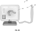
- FIG. 1 illustrates one example of an intraoral scanner as described herein, including a wand 103.
- an intraoral scanner 100 is the iTero ® intraoral digital scanner manufactured by Align Technology, Inc.
- an intraoral scanner may include a hand-held wand 103, which may include an optical system (including projection/imaging optics) comprising one or more lenses and having an optical axis.
- the apparatus may also include illumination optics.
- the apparatus can comprise an axial scanner (e.g., a depth scanning module) that is configured to be move the projection/imaging optics system along the optical axis.
- the apparatus may include a beam splitter configured to transmit light from the light source (after passing through the pattern) to the object and reflect light returning from the object onto an imaging sensor.
- the apparatus may include an image sensor configured to receive light returning from the object (via the projection/imaging optics) through the beam splitter.
- the apparatus can be configured for 3D scanning to at least a portion of the object, for example, intraoral dental 3D scanning for all derivatives of dental restorative and orthodontics indications.
- the apparatuses for confocal scanning disclosed here can include a confocal illuminator.
- the optical system may include a projection/imaging system or subsystem including projection optics and imaging optics.
- the projection optics and the imaging optics can be configured to share the same optical elements (lenses) and the same optical path.
- the apparatus can comprise the depth scanning module, which comprise a compact linear actuator, for example, a voice coil motor (VCM).
- VCM voice coil motor
- the scanner can comprise a front tip, which can include a 45-degree (e.g., back-heated defogging) fold mirror.
- the scanner may include one or more processors and may include on ore more illumination sources (LEDs, lasers, etc.).
- the hand-held wand 103 also include a window 107 providing optical access into the scanner.
- the window may include an optically transparent cover.
- the scanner may be wireless or wired to additional components of the system, including one or more additional processors.
- the scanner may generally illuminate and/or image in the visible spectrum, in the infrared or near-infrared spectrum, in the florescence spectrum, etc.
- a display 105 may also be included as part of the system.
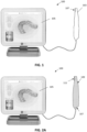
- the intraoral scanner shown in FIG. 1 may be used with one or more sleeves, as shown in FIGS. 2 and 3 .
- the intraoral scanner 100 includes a protective sleeve 109 that is placed over the hand-held wand 103, so that a sleeve window 111 is aligned with the window in the scanner 107 (not visible in FIG. 2A ).
- FIG. 2B shows an alternative variation in which the sleeve 109 is longer, extending over the wand and connecting cable.
- the sleeve shown in FIG. 2B includes a sleeve extension; the distal end of the sleeve (the sleeve body) may be formed to have a more rigid or semi-rigid body, while the more proximal end extending from this sleeve body may be more flexible.
- the sleeve body is formed from the same material (e.g., poly a polyethylene material) as the sleeve extension; the two regions may be laser welded together. The difference in rigidity of these regions may depend on the thickness of the material.
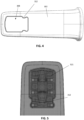
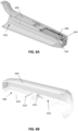
- FIGS. 3A-3B illustrate two examples of protective sleeves 309, 309' as described herein.
- FIG. 3A shows the sleeve body 302, which may be an elongate and hollow body having a distal end 304 and a proximal end 306, wherein the very distal end (of the distal end region) is tapered and closed, and the proximal end is open to receive an intraoral scanner wand.
- the sleeve also includes a window opening 308 that is covered by a transparent cover 310.
- the base (the proximal end) of the sleeve body in this example is flared outwards 314.
- FIG. 3B shows another example of a sleeve that is very similar to that shown in FIG 3A but includes a pair of protruding regions 312 at the window periphery, which project slightly into the field of view of a wand that is inserted into the inner hollow body of the sleeve.
- any of the sleeves may include a notch, protrusion (e.g., bumps, projections, etc.) on the sleeve window, such as the periphery of the sleeve window, that may be within the field of view of the intraoral scanner when the sleeve is attached and may be detected by the intraoral scanner.
- the protrusion is formed of the window of the sleeve itself in an area that is exposed to the camera, as shown in FIGS. 4 and 5 .
- the region just next to the protrusions may include opening through which one or more light sources (e.g., LEDs) in the wand may project light for scanning.
- the projections 312 are shown extending from the edge of the window into the field of view of the camera(s) in the wand 521, when the wand is inserted into the sleeve as shown.
- the sleeves described herein may be fabricated as a single unitary device, to which (in some examples) the transparent cover may be added.
- the material of the entire sleeve may be transparent, and the transparent cover may be integrated (and integrally formed) with the rest of the body of the sleeve.
- the body of the sleeve is formed of a polymeric material such as PE (Polyethylene) or materials that include PE with other materials.
- PE Polyethylene
- the sleeve may be formed of a mixture of HDPE and LDPE (e.g., between 60-95% HDPE and between 5-40% LDPE).
- the PE may be laser welded as described herein to secure, e.g., the extension region.
- any of the sleeves described herein may include one or more internal (within the hollow cavity of the sleeve) guiding structures, such as ramps, to guide and/or lock (e.g., releasably lock) the wand in position so that it is aligned and/or secured within the sleeve.
- Any of these internal guiding structures may also be retainers that retain (releasably retain) the wand within the sleeve and prevent it from moving substantially within the sleeve, which may miss-align the wand imaging optics and the transparent cover (or window) of the sleeve.
- the internal guiding structure is formed integrally (as a single piece, e.g., as by injection molding) with the body of the sleeve.
- the internal guiding structure may be configured as a ramp that is positioned just proximal (e.g., within about 1 cm, within about 2 cm, within about 3 cm, within about 4 cm, within about 5 cm, within about 6 cm, within about 7 cm, within about 8 cm, within about 9 cm, within about 10 cm, etc.) to the window opening region of the sleeve, on the internal surface of the sleeve.
- the internal guiding structure is a ramp formed of a plurality of triangular ribs or wings that extend from the inside of the sleeve body.
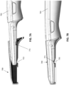
- FIGS. 6A and 6B illustrate cross-sections of an example of a sleeve similar to those shown in FIGS. 3A-3B .
- FIG. 6B shows the inside 630 of the sleeve 609 including an internal guiding structure 633 configured as a ramp or slide.
- an internal guiding structure 633 configured as a ramp or slide.
- only a single ramp/slide is shown; additional ramps/slides may be positioned adjacent to the window (in the half of the sleeve not shown in FIG. 6B for example).
- the internal guiding structure may generally have a surface that extends from the inner wall of the sleeve up above the height of the window region relative to the inter wall, which may guide the wand and prevent it from scraping or scratching the inside of the window region 608 of the sleeve (e.g., the transparent cover in variations including a transparent cover).
- FIGS. 6C-6E illustrate examples of internal guiding structure (e.g., ramps) that may be used, shown in cross-section.
- the internal guiding structure e.g., ramps
- the internal guiding structure has an approximately triangular cross-section for guiding a wand into the hollow distal end of the sleeve. As the wand is slid distally 678, it may be guided by the ramp distal face to side up, away from the edge of the window 608.
- the distal face has an angle 670, 670', 670" relative to the wall of the cover from which it is formed (and extends into the inner hollow of the sleeve) that may be between about 10 degrees and about 50 degrees (e.g., between about 10 degrees and about 45 degrees, between about 10 degrees and 40 degrees, between about 15 degrees and 50 degrees, etc.).
- the ramp is offset a distance 675 from the window opening 608 and thus the transparent cover 610.
- the opposite side of the ramp may also be curved and form a ramp face that may help remove the wand from the sleeve back over the ramp; in some variations this second, proximal-facing ramp may be angled relative to the wall of the cover from which the ramp is formed with a greater angle than the distal-facing ramp.
- the angle 671, 671', 671" of the proximal-facing ramp may be between about 15 and about 90 degrees.
- Either or both the distal-facing ramp and the proximal-facing ramp may have a continuous (e.g., smooth) curve as shown in FIGS. 6A-6D .
- the proximal-facing ramp is an abrupt transition (having a 90-degree angle).
- the spacing (offset distance) 675, 675', 675" between the ramp and the window opening may be, e.g., between about 1 mm and about 2 cm (e.g., between 1 mm and 1 cm, between 1 mm and 9 mm, etc.).
- the internal guiding structure is not offset from the edge of the window region 608, but may be immediately adjacent to it.
- the internal guiding structure is a ramp having a triangular cross-section in which the top of the ramp is shown with a curved corner 673. This corner may be rounded (as shown) or sharp. In some examples the top is flattened.
- the internal guiding structure may have a trapezoidal shape (which may have sharp or rounded edges).
- the examples of internal guiding structures shown in FIGS. 6C-6E are also shown with sleeves in which the transparent cover 610 of the window region 608 is shown schematically on the inside of the cover.
- the transparent cover may be on the outside surface 678 or may be flush (e.g., within a seating region) of the window region.
- the internal guiding structure 633 may comprise a plurality of fins, as shown in FIG. 6B .
- the internal guiding structure includes two thin fin-like lengths extending in the proximal-to-distal direction within the inside of the sleeve and having a triangular longitudinal cross-section.
- the proximal-facing side of each ramp may be connected to a surface that extends between the fins (forming a proximal-facing surface).
- This proximal-facing surface may be optional; in some examples the internal guiding structure is formed of an arrangement of spaced apart (e.g., by 0.1 mm, 0.2 mm, 0.3 mm, 0.4 mm, 0.5 mm, 0.7 mm, 0.8 mm, 1 mm, 1.1 mm, 1.2 mm, etc., between 0.1 mm and 3 mm, between 0.1 mm and 2 mm, between 0.1 mm and 1.5 mm, between 0.1 mm and 1 mm, etc.) the fins extending from the inner wall of the body of the sleeve. Any number of fins (e.g., 1, 2, 3, 4, 5, 6, 7, 8, etc.) may be used for each internal guiding structure.
- any number of fins e.g., 1, 2, 3, 4, 5, 6, 7, 8, etc.
- the transparent cover is attached on the inside of the sleeve, as shown in FIG. 6A .
- the transparent cover 610 forming a portion of the window region 608 is sealed to the periphery of the window region by a foam (window foam) material.
- the foam may be, for example, MED 5696R Adhesive foam (e.g., Avery Dennison) or MED 2123R adhesive (Vancive Medical Technologies).
- the foam may be compressible and may adhesively secure the transparent cover to the body of the sleeve.
- Some examples of the sleeves described herein do not include foam.
- an elastic material may be used instead of foam.
- the elastic material may be an adhesive that can be applied as a liquid or gel (or paste) but that cures into a solid, forming a seal between the body of the sleeve and the transparent cover.
- the cover may be applied over the distal end of a wand, for example by sliding the wand into the cover or by sliding the cover over the wand, or some combination.
- the wand of the intraoral scanner may slide within the hollow inner region of the sleeve and the internal guiding structure (ramp) may deflect the distal tip up and away from the transparent window (e.g., in some examples the transparent cover of the window) which may protect the transparent window and allow the wand to be positioned optimally relative to the sleeve.
- FIGS. 7A-7B illustrate one method of attaching a cover 709 to a wand of an intraoral scanner 703.
- the distal end of the wand is inserted into the distal end opening of the sleeve, and advanced to the internal guiding structure (e.g., ramp or slide 70).
- the internal guiding structure guides the tip of the wand above the window region and may act as a securement to reliably hold the wand in position, as shown in FIG. 7B .
- the wand includes an engagement region 771 for engaging the internal guiding structure.
- the internal guiding structure may fit into the engagement region of the wand, allowing the tip of the wand, including the imaging window of the wand, to be aligned with the window region of the sleeve in a fixed position.
- the engagement region may also engage releasably hold the wand in this position relative to the sleeve until the sleeve is withdrawn proximally.
- the imaging window of the wand may push down against the window region, which may include a foam material, as described above, which may be compressed.
- the wand of the intraoral scanner may be disengaged from the internal guiding structure by pulling the wand proximally (and/or the sleeve distally) with sufficient force so that the sidewall of the engagement region slides along the proximal-facing side of the internal guiding structure, driving the wand up, away from the window region of the sleeve, and allowing it to be withdrawn out of the sleeve.
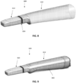
- any of the sleeves described herein may include a sleeve extension portion that extend proximally from the more rigid (or semi-rigid) proximal end, as shown in the examples of FIGS. 8 and 9 .
- the sleeve 809 includes a more rigid distal sleeve portion 810 and a more flexible proximal sleeve extension portion 819.
- the proximal sleeve portion may be attached to the distal sleeve by an adhesive or a weld.
- the sleeve extension is welded (e.g., laser welded) 854 to the sleeve (the distal portion of the sleeve).
- the material forming the sleeve extension may be the same as the material of the distal portion of the sleeve (e.g., polyethylene or a mixture of polyethylene and other polymers or other forms of polyethylene).
- the sleeve extension may be configured to invert over itself when pulled distally, such as when removing the sleeve from over the wand.
- FIG. 9 shows an example of the sleeve of FIG. 8 applied over a wand 803 of an intraoral scanner.
- the sleeve extension may extend for between 5 inches and 5 feed from the distal sleeve portion (e.g., between 6 inches and 4 feet, etc.).
- the sleeve extension may be configured to roll up over itself for removal, so as to trap any contamination on the outer surface of the sleeve within the rolled-up portion.
- the sleeve extension be tapered with a wider proximal end than the distal region coupled to the distal (more rigid) sleeve region.
- the sleeve extension may be biased (pre-rolled) back over itself.
- a new and clean sleeve may include a rolled-up sleeve extension that may be rolled out proximally when applied over the wand.
- the rolled-up sleeve may be rolled so that the more distal portion is rolled within the more proximal portion.
- Once rolled out the sleeve extension may remain unrolled during use (and is some examples may include a fastener, such as an adhesive and/or tie, to remain unrolled and applied over the wand or cord of the wand) until it is removed.
- the sleeve extension may therefore be biased to roll back up to the original configuration.
- FIGS. 10A-10H illustrate outer views of one example of a sleeve; as in any of the sleeves descried and illustrated herein, a sleeve extension region may be included, but not shown.
- the example sleeve in FIGS. 10A-10H is similar to the sleeve shown in FIG. 3B .
- the sleeve in FIGS 10A-10H may include an elongate and hollow body 1041 having a distal end and a proximal end. As mentioned, the body may be rigid or semi-rigid. This body may also be referred to as the distal sleeve region in any of the sleeves described herein.
- the distal end of the sleeve 1043 is tapered and closed.
- the taper is rounded, as shown, and is compressed down so that a section through the distal end region forms a squrcle (a rounded square or rectangle) and/or ovoid cross-section, as shown in the bottom and top views of FIGS. 10C and 10D , respectively, as well as the side views of FIGS. 10E and 10F .
- the proximal end is opened 1014 to receive an intraoral scanner.
- a flexible sleeve extension may be attached to the proximal end of the more rigid distal sleeve.
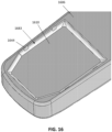
- the sleeve of FIGS. 10A-10H also includes a window opening 1008 on a lateral side of the distal end region.
- the sleeve includes a transparent cover 1010 over the window opening.
- FIGS. 11A-11C illustrate another example 1106 of a sleeve similar to that shown in FIG. 3A , described above.
- the example shown in FIGS. 11A-11C has the same side views, top view and bottom views, and back view as the example shown in FIGS. 10A-10H .
- any of the sleeves described herein may also or alternatively a transparent cover (e.g., window) that is installed from (and in some examples onto) the outside of the sleeve. Fabrication of sleeves in which the transparent window may be installed from the outside of the sleeve rather than the inside may be much easier and less expensive as compared to mounting the transparent cover from the inside (or on an inside surface).
- Some of the sleeve examples described herein may be molded (e.g., by molding, extruding, etc.) with a window opening formed in the device. The transparent cover may then be mounted to the sleeve from the outer surface.
- any of the devices described herein may include a receiving area in the distal region of the body of the sleeve around the window opening of the sleeve.
- the receiving area may be a transparent cover (e.g., window) receiving area that may seat and secure the transparent cover.
- the receiving area may be configured to seat the transparent cover in a particular orientation; for example, the receiving area may include a recessed region (recessed from the outer surface of the sleeve) that may include a lip or edge around the window opening through the sleeve on which the transparent cover may sit.
- the receiving area may include a channel or passage on or adjacent to the seating lip or edge for holding a sealing material, including a liquid or gel adhesive material that may polymerize into the seal.
- any of the receiving areas described herein may include one or more fasteners for securing the transparent cover in the seating area.
- the seating area may be recessed into the body of the sleeve, as described; alternatively or additionally the seating area may extend proud of the body of the sleeve.
- any of the sleeves described herein may include a sealing frame that may fit over a transparent cover (e.g., window) receiving area around the window region.
- FIGS. 12A-12B illustrate a section through another example of a sleeve in which a wan of an intraoral scanner 1236 has been inserted.
- the sleeve includes a receiving area 1235 and a sealing frame 1231 that is shown coupled to an outside of the elongate and hollow body 1241 of the sleeve so that the transparent cover 1210 is sandwiched between a periphery (e.g., the receiving or seating area 1235, which may be a lip or ledge) of the window opening and a sealing frame window opening.
- FIG. 12B shows an enlarged view of region 12B of FIG. 12A .
- the sealing frame 1231 may include a channel or passage 1237 ("adhesive ditch") within which an adhesive material (e.g., gel, liquid, etc.) may be applied to secure the transparent cover over the window opening, e.g., by sealing between the sealing frame and the receiving area 1235 around the window.
- an adhesive material e.g., gel, liquid, etc.
- either or both the sealing frame and the body of the sleeve may include an adhesive channel that may peripherally surround at least partially around the sealing frame window opening, allowing holding an adhesive securing the transparent cover within the window opening.
- the wand when the wand is fully engaged with the sleeve, the wand may include portion on or adjacent to the imaging window of the wand through which images may be captured that may rest against the transparent cover.
- the wand may include a metal spacing projection 1238 adjacent to the imaging window of the wand that may sit directly against 1239 the transparent cover of the sleeve, as shown. In some variations this connection may allow for anti-fogging (e.g., heating) of the transparent cover.
- This configuration in which a portion of the wand contacts (e.g., presses against) the wand may be configured so that the imaging window of the wand is precisely positioned relative to the window of the sleeve.
- the spacing projection 1238 of the wand contacting the window may be referred to as a spacing portion or spacing projection of the wand, and may be metal or non-metal (e.g., plastic).
- the sealing frame 1231 may be secured to the body of the sleeve (the rigid or semi-rigid distal portion of the sleeve) by an adhesive and/or by a mechanical fastener such as a snap or the like.
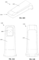
- FIGS. 13A-13B illustrate another example of a sleeve including a sealing frame 1331 that seals a transparent cover 1310.
- the window may be placed into the seating region of the sleeve, which is sized and configured to receive the transparent cover as shown.
- the transparent cover may be easily positioned without requiring force (pressure) to be applied.
- an adhesive may be applied to the periphery of the sealing frame 1311 such as within a channel ("adhesive ditch") 1327 and the sealing frame 1331 may be applied over and into the receiving area of the sleeve as shown in FIG. 13B .
- the receiving area 1331 is recessed so that the sealing frame sits flush with the outer surface of the sleeve when the sealing frame is secured down.
- the sealing frame may also or alternatively be secured to the rest of the sleeve by one or more snaps 1344.
- the frame may mechanically hold the transparent cover in place until the adhesive is cured, without requiring a fixing jig.
- the sleeve may include a receiving area in the distal region of the body of the sleeve around the window opening of the sleeve that is configured to receive and hold a transparent cover without requiring a sealing frame.
- the transparent window is secured by an adhesive applied around the window opening 1408 of the body of the sleeve 1406 either before or after the transparent window has been applied.
- FIG. 14 shows one variations of a sleeve in which a seating region is included at the distal end.
- the window region includes a peripheral seating area in which one or more snaps are included.
- the snaps are formed from the sleeve body (as a unitary portion) and may include a ramped overhang portion 1546 and an undercut region; the transparent cover 1510 edge may slide against the ramped overhang portion and displace (e.g., bend) it out of the way (or may itself bend out of the way) so that it may seat into the seating region 1535, as shown in FIG. 15 .
- An adhesive may be applied around the periphery of the window opening to seal the transparent cover within the window opening (not shown).
- FIG. 15 also shows a section through the sleeve while the sleeve is being worn over a wand of an intraoral scanner 1536.
- the wand also includes one or more spacing projection regions 1538 that may contact the transparent cover 1510.
- FIG. 16 illustrates the sleeve of FIG. 15 with an adhesive seal 1683 (which may be fully cured) shown.
- the transparent cover (window 1610) is held in place by the snaps 1644 formed integrally into the body along with the seating region of the sleeve 1606.
- one of the sides of the window opening may include a shelf and an overhang rather than a snap; the overhang may secure the transparent cover on one side and one or more snaps may be on the opposite side of the window opening and shelf (seating area).
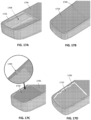
- FIGS. 17A-17D illustrate one example of a sleeve in which the transparent cover is heat-pressed (heat staked) in position.
- the body of the sleeve 1706 includes a window opening 1708 with a seating area 1735 having a lip around the perimeter of the window opening.
- a transparent cover that fits the seating area may be positioned onto the seating area from outside of the sleeve, as shown in FIG. 17B.
- FIG. 17C shows that multiple regions of the periphery may then be deformed to secure the transparent cover within the seating area, by (in one example) heat pressing.
- a heat may be applied at one or more points to melt and deform the polymeric peripheral region so that it forms a heat stake 1789 that extends over and locks the transparent cover in position, as shown.
- An adhesive sealing material 1783 may then be applied to seal the edges of the transparent window 1710 to the sleeve, as shown in FIG. 17D .
- this sleeve example may also be formed as a single injected part implementation into which the transparent window may be attached.
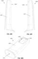
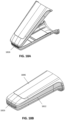
- FIGS. 18A and 18B illustrate an example of a sleeve having a body that is formed as a clamshell including a living hinge region that may be molded or otherwise formed as a single piece (e.g., by injection molding) and may be closed along the living hinge to form the hollow sleeve (e.g., the distal, rigid/semi-rigid sleeve portion).
- FIG. 18A shows the body prior to closing (or during closing) while FIG. 18B shows the sleeve in the closed configuration.
- FIGS. 19A and 19B illustrate an example of a sleeve body similar to that shown in FIGS. 18A-18B prior to folding about the hinge region 1926.
- the body includes two halves forming the front 1926 and back 1928 of the sleeve, separated by a living hinge.
- the window opening 1908 through the front side is included.
- the window opening includes a seating area 1935 on the inner side of the sleeve in which the transparent cover may be positioned and secured.
- Region 19B is shown in greater detail in FIG. 19B .
- the edge of the front and back sides of the sleeve may be configured to mate with each other with a friction fit (e.g., by including lips or ridges 1829 that may engage with each other when assembled and closed together). This region may be welded as mentioned above.
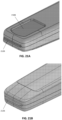
- FIGS. 20A and 20B Prior to closing and sealing, the transparent cover may be added, as illustrated in FIGS. 20A and 20B .
- an adhesive may be applied in the seating area 2035 and the transparent cover 2010 may be placed 2069 onto the seating area, as shown in FIG. 20B .
- the body may then be folded (by folding the top 2026 together with the bottom 2028) to form the closed and sleeve 2006, as shown in FIG. 20C , and the closed edges 2022 may be sealed, as mentioned above.
- a sleeve extension may optionally be added.
- FIGS. 21A and 21B show the distal end, including the hinge region (configured das a living hinge in this example) in greater detail.
- FIG. 21A shows the front, including the window formed by the transparent cover 2110.
- FIG. 21B shows the back.
- any of the sleeves described herein may include features shown in any of these examples.
- Other sleeve designs may also incorporate all or some of these features.
- the sleeve may be fabricated as a single piece, including the transparent window; for example, the entire sleeve (e.g., the sleeve distal end in regions including a sleeve extension) may be transparent.
- a transparent sleeve including an integral transparent cover may include the internal guiding structure (e.g., ramp) as described herein.
- the sleeves described herein may be configured to withstand pressure of at least about 50 kPa, such as at least about 60 kPa, at least about 70 kPa, at least about 80 kPa, at least about 90 kPa, at least about 100 kPa, etc.
- the sleeve may be configured, e.g., by the position of the seating area for the window, so that there is a minimum separation between the sleeve window (transparent cover) and the imaging window of the wand.
- the minimum clearance between the sleeve window and the imaging window may be about 0.1 mm, about 0.2 mm, about 0.3 mm, etc. This minimum distance may also be maintained in part based on a spacing projection adjacent to the imaging window of the wand, as described above.
- any of the sleeves described herein may include a flavor.
- the sleeve (particularly the distal end region) may be coated or may incorporate a flavorant. Any appropriate flavorant may be used. Flavorants may be coated by dipping, spraying or the like.
- systems and/or sleeves described herein may be configured for single, one-time (e.g., one continuous session) or a limited duration of time use.
- Any of the methods (including user interfaces) described herein may be implemented as software, hardware or firmware, and may be described as a non-transitory computer-readable storage medium storing a set of instructions capable of being executed by a processor (e.g., computer, tablet, smartphone, etc.), that when executed by the processor causes the processor to control perform any of the steps, including but not limited to: displaying, communicating with the user, analyzing, modifying parameters (including timing, frequency, intensity, etc.), determining, alerting, or the like.
- a processor e.g., computer, tablet, smartphone, etc.
- references to a structure or feature that is disposed "adjacent" another feature may have portions that overlap or underlie the adjacent feature.
- the device may be otherwise oriented (rotated 90 degrees or at other orientations) and the spatially relative descriptors used herein interpreted accordingly.
- the terms “upwardly”, “downwardly”, “vertical”, “horizontal” and the like are used herein for the purpose of explanation only unless specifically indicated otherwise.
- first and second may be used herein to describe various features/elements (including steps), these features/elements should not be limited by these terms, unless the context indicates otherwise. These terms may be used to distinguish one feature/element from another feature/element. Thus, a first feature/element discussed below could be termed a second feature/element, and similarly, a second feature/element discussed below could be termed a first feature/element without departing from the teachings of the present invention.
- any of the apparatuses and methods described herein should be understood to be inclusive, but all or a sub-set of the components and/or steps may alternatively be exclusive and may be expressed as "consisting of” or alternatively “consisting essentially of” the various components, steps, sub-components or sub-steps.
- a numeric value may have a value that is +/- 0.1% of the stated value (or range of values), +/- 1% of the stated value (or range of values), +/- 2% of the stated value (or range of values), +/- 5% of the stated value (or range of values), +/- 10% of the stated value (or range of values), etc.
- Any numerical values given herein should also be understood to include about or approximately that value, unless the context indicates otherwise. For example, if the value "10" is disclosed, then “about 10" is also disclosed. Any numerical range recited herein is intended to include all sub-ranges subsumed therein.
Landscapes
- Health & Medical Sciences (AREA)
- Life Sciences & Earth Sciences (AREA)
- Surgery (AREA)
- Veterinary Medicine (AREA)
- Public Health (AREA)
- Physics & Mathematics (AREA)
- General Health & Medical Sciences (AREA)
- Optics & Photonics (AREA)
- Animal Behavior & Ethology (AREA)
- Biophysics (AREA)
- Pathology (AREA)
- Engineering & Computer Science (AREA)
- Biomedical Technology (AREA)
- Heart & Thoracic Surgery (AREA)
- Medical Informatics (AREA)
- Molecular Biology (AREA)
- Radiology & Medical Imaging (AREA)
- Nuclear Medicine, Radiotherapy & Molecular Imaging (AREA)
- Oral & Maxillofacial Surgery (AREA)
- Dentistry (AREA)
- Epidemiology (AREA)
- Endoscopes (AREA)
- Dental Tools And Instruments Or Auxiliary Dental Instruments (AREA)
Claims (14)
- Hülse (609) für einen intraoralen Scanner (100), wobei die Hülse umfasst:einen länglichen und hohlen Körper (1041) mit einem distalen Ende und einem proximalen Ende, wobei das distale Ende verjüngt und geschlossen ist und das proximale Ende offen ist, um einen intraoralen Scanner aufzunehmen;eine Fensteröffnung (608) auf einer lateralen Seite des distalen Endes;eine transparente Abdeckung (610) über der Fensteröffnung undeine Rampe (633), die integral mit dem länglichen und hohlen Körper geformt ist, wobei die Rampe innerhalb des hohlen Körpers proximal zu der Fensteröffnung positioniert ist und dazu konfiguriert ist, ein distales Ende des intraoralen Scanners von der Fensteröffnung weg zu leiten, wenn der intraorale Scanner in die Hülse eingeführt wird, und dadurch gekennzeichnet, dass die Rampe eine Vielzahl von Rippen umfasst, die sich in einer proximalen zu einer distalen Richtung innerhalb des hohlen Körpers erstrecken.
- Hülse nach Anspruch 1, weiterhin umfassend einen Schaumstoff zumindest zum Teil umfänglich um die Fensteröffnung innerhalb des hohlen Körpers, wobei die transparente Abdeckung gegen den Schaumstoff gesichert ist.
- Hülse nach Anspruch 1, weiterhin umfassend eine Hülsenverlängerung (819), die sich von dem proximalen Ende des länglichen und hohlen Körpers erstreckt.
- Hülse nach Anspruch 3, wobei die Hülsenverlängerung dazu konfiguriert ist, sich auf sich selbst umzukehren, wenn sie distal gezogen wird.
- Hülse nach Anspruch 1, wobei die Hülse aus einem Polyethylenmaterial hergestellt ist.
- Hülse nach Anspruch 1, weiterhin umfassend eine Klebedichtung (1683) um die Fensteröffnung, die die transparente Abdeckung an der Fensteröffnung abdichtet.
- Hülse nach Anspruch 1, weiterhin umfassend einen Dichtungsrahmen (1231), der an eine Außenseite des länglichen und hohlen Körpers gekoppelt ist, so dass die transparente Abdeckung zwischen einem Rand der Fensteröffnung und einer Dichtungsrahmenfensteröffnung eingeschoben ist.
- Hülse nach Anspruch 7, wobei der Dichtungsrahmen durch eine oder mehrere Schnappverschlüsse (1344) an den länglichen und hohlen Körper gekoppelt ist.
- Hülse nach Anspruch 7, wobei der Dichtungsrahmen einen Klebekanal (1327) umfasst, der am Rand um die Dichtungsrahmenfensteröffnung eingerichtet ist.
- Hülse nach Anspruch 7, wobei der längliche und hohle Körper eine Auflageregion (1535) umfasst, die dazu konfiguriert ist, die transparente Abdeckung zu halten, weiterhin wobei der Dichtungsrahmen dazu konfiguriert ist, die Auflageregion zu sichern, so dass eine Außenfläche des Dichtungsrahmens mit einer Außenfläche des länglichen und hohlen Körpers bündig ist.
- Hülse nach Anspruch 1, wobei der längliche und hohle Körper eine Auflageregion umfasst, die dazu konfiguriert ist, die transparente Abdeckung zu halten, weiterhin umfassend eine Vielzahl von Schnappern, die von dem Rand der Fensteröffnung in die Auflageregion vorragen, wobei die Schnapper dazu konfiguriert sind, die transparente Abdeckung innerhalb der Auflageregion zu sichern.
- Hülse nach Anspruch 1, wobei der längliche und hohle Körper eine Auflageregion umfasst, die dazu konfiguriert ist, die transparente Abdeckung zu halten, weiterhin wobei die Fensteröffnung eine Vielzahl von Wärmepressrasten umfasst, die von dem Rand der Fensteröffnung in die Fensteröffnung vorragen, wobei die Wärmepressrasten dazu konfiguriert sind, die transparente Abdeckung innerhalb der Auflageregion zu sichern.
- Hülse nach Anspruch 1, wobei der längliche und hohle Körper einen Muschelschalenkörper mit einem Filmscharnier (1826) an dem distalen Ende des länglichen und hohlen Körpers umfasst, weiterhin wobei eine laterale Naht an beiden Seiten des länglichen und hohlen Körpers abgedichtet geschlossen ist.
- Hülse nach Anspruch 1, wobei die Hülse einen Geschmacksstoff umfasst, die der Hülse einen Geschmack gibt.
Applications Claiming Priority (2)
| Application Number | Priority Date | Filing Date | Title |
|---|---|---|---|
| US202163189915P | 2021-05-18 | 2021-05-18 | |
| PCT/US2022/029780 WO2022245906A1 (en) | 2021-05-18 | 2022-05-18 | Intraoral scanner sleeve |
Publications (3)
| Publication Number | Publication Date |
|---|---|
| EP4340773A1 EP4340773A1 (de) | 2024-03-27 |
| EP4340773C0 EP4340773C0 (de) | 2025-05-21 |
| EP4340773B1 true EP4340773B1 (de) | 2025-05-21 |
Family
ID=82019950
Family Applications (1)
| Application Number | Title | Priority Date | Filing Date |
|---|---|---|---|
| EP22729932.8A Active EP4340773B1 (de) | 2021-05-18 | 2022-05-18 | Intraorale scannerhülse |
Country Status (4)
| Country | Link |
|---|---|
| US (2) | US12329358B2 (de) |
| EP (1) | EP4340773B1 (de) |
| CN (1) | CN117355280A (de) |
| WO (1) | WO2022245906A1 (de) |
Families Citing this family (8)
| Publication number | Priority date | Publication date | Assignee | Title |
|---|---|---|---|---|
| AU2016380989A1 (en) | 2015-12-29 | 2018-07-12 | CEEK Women’s Health, Inc. | Sleeve for speculum and use thereof |
| US10507087B2 (en) | 2016-07-27 | 2019-12-17 | Align Technology, Inc. | Methods and apparatuses for forming a three-dimensional volumetric model of a subject's teeth |
| EP4792730A2 (de) | 2018-01-26 | 2026-08-19 | Align Technology, Inc. | Intraorales abtastsystem |
| US11096765B2 (en) | 2018-06-22 | 2021-08-24 | Align Technology, Inc. | Light field intraoral 3D scanner with structured light illumination |
| USD924397S1 (en) * | 2018-10-11 | 2021-07-06 | Ceek Women's Health, Inc. | Medical device sleeve |
| EP4371526B1 (de) * | 2022-11-21 | 2025-06-11 | 3Shape A/S | Intraorales scansystem |
| US20240268934A1 (en) * | 2023-02-10 | 2024-08-15 | Jeffery A. Scolnick | Offset IntraOral Cavity Scanner |
| US12685620B2 (en) | 2023-08-11 | 2026-07-21 | Align Technology, Inc. | Image-based longitudinal analysis |
Citations (3)
| Publication number | Priority date | Publication date | Assignee | Title |
|---|---|---|---|---|
| US20200163533A1 (en) * | 2017-06-14 | 2020-05-28 | Dentsply Sirona Inc. | Window system for an intraoral scanner |
| US20200315434A1 (en) * | 2019-04-05 | 2020-10-08 | Align Technology, Inc. | Intraoral scanner sleeve authentication and identification |
| WO2021021854A1 (en) * | 2019-07-29 | 2021-02-04 | Align Technology, Inc. | Full-scanner barrier for an intra-oral device |
Family Cites Families (143)
| Publication number | Priority date | Publication date | Assignee | Title |
|---|---|---|---|---|
| US3769980A (en) * | 1971-06-28 | 1973-11-06 | Medical Concepts Inc | Medical instruments |
| JPS5850881Y2 (ja) * | 1978-07-27 | 1983-11-19 | オリンパス光学工業株式会社 | 内視鏡 |
| DE4226612A1 (de) * | 1992-08-11 | 1994-02-17 | Siemens Ag | Verfahren und Vorrichtung zur Bearbeitung von Zahnhartsubstanz |
| US20030107652A1 (en) * | 1992-09-11 | 2003-06-12 | Williams Ronald R. | Dental video camera |
| US5408992A (en) * | 1993-11-05 | 1995-04-25 | British Technology Group Usa Inc. | Endoscopic device for intraoral use |
| JP2802244B2 (ja) * | 1994-08-29 | 1998-09-24 | オリンパス光学工業株式会社 | 内視鏡用シース |
| EP0840574B1 (de) | 1995-07-21 | 2003-02-19 | Cadent Ltd. | Verfahren und system zur dreidimensionalen bilderfassung von zähnen |
| IL120867A0 (en) | 1997-05-20 | 1997-09-30 | Cadent Ltd | Computer user interface for orthodontic use |
| IL120892A (en) | 1997-05-22 | 2000-08-31 | Cadent Ltd | Method for obtaining a dental occlusion map |
| US6334772B1 (en) | 1997-09-30 | 2002-01-01 | Cadent Ltd. | Placing an orthodontic element on a tooth surface |
| US7507088B2 (en) | 1997-09-30 | 2009-03-24 | Cadent Ltd. | Method for comparing orthodontic element placement |
| IL125659A (en) | 1998-08-05 | 2002-09-12 | Cadent Ltd | Method and device for three-dimensional simulation of a structure |
| IL126838A (en) | 1998-11-01 | 2003-04-10 | Cadent Ltd | Dental image processing method and system |
| US6641530B2 (en) * | 1998-12-14 | 2003-11-04 | Fuji Photo Optical Co., Ltd. | Endoscope with objective lens drive mechanism |
| US6095811A (en) * | 1999-01-27 | 2000-08-01 | Welch Allyn, Inc. | Gripping handle for diagnostic instrument |
| US7914442B1 (en) * | 1999-03-01 | 2011-03-29 | Gazdzinski Robert F | Endoscopic smart probe and method |
| US6379296B1 (en) * | 1999-03-26 | 2002-04-30 | Richard W. Baggett | Medical lighting device |
| US6542249B1 (en) | 1999-07-20 | 2003-04-01 | The University Of Western Ontario | Three-dimensional measurement method and apparatus |
| EP1237464B1 (de) * | 1999-12-08 | 2005-07-20 | X-Rite Incorporated | Optisches messgerät |
| US7373286B2 (en) | 2000-02-17 | 2008-05-13 | Align Technology, Inc. | Efficient data representation of teeth model |
| US6463344B1 (en) | 2000-02-17 | 2002-10-08 | Align Technology, Inc. | Efficient data representation of teeth model |
| US6633789B1 (en) | 2000-02-17 | 2003-10-14 | Align Technology, Inc. | Effiicient data representation of teeth model |
| WO2003057041A1 (en) | 2002-01-14 | 2003-07-17 | Cadent Ltd. | Method and sytem for imaging a patient's teeth arrangement |
| US7255558B2 (en) | 2002-06-18 | 2007-08-14 | Cadent, Ltd. | Dental imaging instrument having air stream auxiliary |
| US6979196B2 (en) | 2002-06-21 | 2005-12-27 | Align Technology, Inc. | Systems and methods for automated bite-setting of tooth models |
| US7030383B2 (en) | 2003-08-04 | 2006-04-18 | Cadent Ltd. | Speckle reduction method and apparatus |
| US7202466B2 (en) | 2003-08-25 | 2007-04-10 | Cadent Ltd. | Apparatus and method for providing high intensity non-coherent light and for speckle reduction |
| US8371848B2 (en) * | 2003-12-08 | 2013-02-12 | J. Morita Manufacturing Corporation | Dental diagnostic and treatment apparatus |
| US7698068B2 (en) | 2004-06-17 | 2010-04-13 | Cadent Ltd. | Method for providing data associated with the intraoral cavity |
| US7610647B2 (en) * | 2004-09-03 | 2009-11-03 | S.C. Johnson & Son, Inc. | Cleaning system |
| US7347868B2 (en) * | 2004-10-26 | 2008-03-25 | Baronova, Inc. | Medical device delivery catheter |
| JP5154955B2 (ja) | 2005-03-03 | 2013-02-27 | カデント・リミテツド | 口腔スキャニング用システムおよび方法 |
| JP4648780B2 (ja) * | 2005-07-11 | 2011-03-09 | Hoya株式会社 | 電子内視鏡用撮像素子パッケージ |
| US20100010308A1 (en) * | 2005-08-17 | 2010-01-14 | Michael Braun | Hygiene protector for endoscopes, endoscope with hygiene protector, and method for fitting a hygiene protector onto an endoscope |
| JP5693846B2 (ja) * | 2006-07-21 | 2015-04-01 | オンコスコープ・インコーポレーテツド | 特に内視鏡用途に使用される光ファイバプローブで使用するための保護プローブ先端 |
| US7916911B2 (en) | 2007-02-26 | 2011-03-29 | Align Technology, Inc. | System and method for digital tooth imaging |
| CA2681883A1 (en) * | 2007-04-11 | 2008-10-23 | Tyco Healthcare Group Lp | Endoscopic/laparoscopic introducer sleeve |
| JP2010528941A (ja) * | 2007-06-01 | 2010-08-26 | ダビッドソン,ローデリック,イアン | 吸収性材料裏地を有する輸送用容器 |
| US10307041B2 (en) * | 2007-06-08 | 2019-06-04 | Medeon Biodesign, Inc. | Lens cover modification |
| US20090069763A1 (en) * | 2007-09-11 | 2009-03-12 | Dicarlo Paul | Flat Expandable Effusion Drain |
| US8388521B2 (en) * | 2008-05-19 | 2013-03-05 | Boston Scientific Scimed, Inc. | Integrated locking device with active sealing |
| US8108189B2 (en) | 2008-03-25 | 2012-01-31 | Align Technologies, Inc. | Reconstruction of non-visible part of tooth |
| KR101706619B1 (ko) | 2008-07-03 | 2017-02-14 | 얼라인 테크널러지, 인크. | 치과 과정에서 사용하기 위한 방법, 장치 및 시스템 |
| US20100041952A1 (en) * | 2008-08-12 | 2010-02-18 | Omnimed Enterprises LLC | Medical Instrument Light Source Connection Device |
| US20100273355A1 (en) * | 2009-04-22 | 2010-10-28 | Tyco Electronics Corporation | Image guide wire connection |
| EP2255748A1 (de) * | 2009-05-29 | 2010-12-01 | 3M Innovative Properties Company | Zahnfleischretraktionszusammensetzung, Herstellungsverfahren dafür und Verwendung davon |
| US8033991B2 (en) * | 2009-09-14 | 2011-10-11 | Artann Laboratories Inc. | Handgrip for assessment of colonoscope manipulation |
| US8587582B2 (en) | 2009-11-02 | 2013-11-19 | Align Technology, Inc. | Generating a dynamic three-dimensional occlusogram |
| US20110106029A1 (en) * | 2009-11-02 | 2011-05-05 | Garren Mary L | Polyp trap |
| US8244028B2 (en) | 2010-04-30 | 2012-08-14 | Align Technology, Inc. | Virtual cephalometric imaging |
| ES2848157T3 (es) | 2010-07-19 | 2021-08-05 | Align Technology Inc | Procedimientos y sistemas para crear e interactuar con modelos virtuales tridimensionales |
| US20120029280A1 (en) * | 2010-07-29 | 2012-02-02 | Cannuflow, Inc. | Arthroscopic System |
| US20120029289A1 (en) * | 2010-07-29 | 2012-02-02 | Cannuflow, Inc. | Optical Cap for Use With Arthroscopic System |
| US20120156634A1 (en) * | 2010-12-21 | 2012-06-21 | The Procter & Gamble Company | Intraoral Imaging Devices And Methods |
| CN103796703B (zh) * | 2011-05-27 | 2016-05-25 | 克纳维医药公司 | 具有流体旋转接头的医疗探针 |
| US20120323069A1 (en) * | 2011-06-17 | 2012-12-20 | Stout Christopher A | Endoscope system adapter |
| JP2013135750A (ja) * | 2011-12-28 | 2013-07-11 | Omron Healthcare Co Ltd | 電動歯ブラシおよび替えブラシ |
| US9192305B2 (en) | 2012-09-28 | 2015-11-24 | Align Technology, Inc. | Estimating a surface texture of a tooth |
| US8948482B2 (en) | 2012-11-01 | 2015-02-03 | Align Technology, Inc. | Motion compensation in a three dimensional scan |
| US9717402B2 (en) | 2012-11-21 | 2017-08-01 | Align Technology, Inc. | Confocal imaging using astigmatism |
| US9668829B2 (en) | 2012-12-19 | 2017-06-06 | Align Technology, Inc. | Methods and systems for dental procedures |
| US10098714B2 (en) | 2012-12-19 | 2018-10-16 | Align Technology, Inc. | Apparatus and method for optically scanning an object in registration with a reference pattern |
| GB2517397A (en) * | 2013-05-17 | 2015-02-25 | Partners For Endoscopy Ltd | A gas and liquid supply system for an endoscope |
| US9393087B2 (en) | 2013-08-01 | 2016-07-19 | Align Technology, Inc. | Methods and systems for generating color images |
| US10111714B2 (en) | 2014-01-27 | 2018-10-30 | Align Technology, Inc. | Adhesive objects for improving image registration of intraoral images |
| US10111581B2 (en) * | 2014-02-27 | 2018-10-30 | Align Technology, Inc. | Thermal defogging system and method |
| US9510757B2 (en) | 2014-05-07 | 2016-12-06 | Align Technology, Inc. | Identification of areas of interest during intraoral scans |
| US9431887B2 (en) | 2014-06-06 | 2016-08-30 | Align Technology, Inc. | Lens positioning system |
| US9491863B2 (en) | 2014-06-26 | 2016-11-08 | Align Technology, Inc. | Mounting system that maintains stability of optics as temperature changes |
| US9261356B2 (en) | 2014-07-03 | 2016-02-16 | Align Technology, Inc. | Confocal surface topography measurement with fixed focal positions |
| US9261358B2 (en) | 2014-07-03 | 2016-02-16 | Align Technology, Inc. | Chromatic confocal system |
| US9439568B2 (en) | 2014-07-03 | 2016-09-13 | Align Technology, Inc. | Apparatus and method for measuring surface topography optically |
| US10772506B2 (en) | 2014-07-07 | 2020-09-15 | Align Technology, Inc. | Apparatus for dental confocal imaging |
| US9693839B2 (en) | 2014-07-17 | 2017-07-04 | Align Technology, Inc. | Probe head and apparatus for intraoral confocal imaging using polarization-retarding coatings |
| US9675430B2 (en) | 2014-08-15 | 2017-06-13 | Align Technology, Inc. | Confocal imaging apparatus with curved focal surface |
| US9724177B2 (en) | 2014-08-19 | 2017-08-08 | Align Technology, Inc. | Viewfinder with real-time tracking for intraoral scanning |
| US9660418B2 (en) | 2014-08-27 | 2017-05-23 | Align Technology, Inc. | VCSEL based low coherence emitter for confocal 3D scanner |
| USD760901S1 (en) | 2014-09-18 | 2016-07-05 | Align Technology, Inc. | Intraoral scanner wand |
| USD742518S1 (en) | 2014-09-18 | 2015-11-03 | Align Technology, Inc. | Intraoral scanner wand |
| GB2531557B (en) * | 2014-10-22 | 2017-02-08 | Keymed (Medical & Ind Equipment) Ltd | Fluid dispensing device |
| US10453269B2 (en) | 2014-12-08 | 2019-10-22 | Align Technology, Inc. | Intraoral scanning using ultrasound and optical scan data |
| JP5977914B1 (ja) * | 2015-01-27 | 2016-08-24 | オリンパス株式会社 | 内視鏡 |
| US10504386B2 (en) | 2015-01-27 | 2019-12-10 | Align Technology, Inc. | Training method and system for oral-cavity-imaging-and-modeling equipment |
| US10076389B2 (en) | 2015-02-13 | 2018-09-18 | Align Technology, Inc. | Three-dimensional tooth modeling using a two-dimensional x-ray image |
| US10108269B2 (en) | 2015-03-06 | 2018-10-23 | Align Technology, Inc. | Intraoral scanner with touch sensitive input |
| USD768861S1 (en) | 2015-03-06 | 2016-10-11 | Align Technology, Inc. | Combined desktop display and computer for intraoral scanner |
| US9451873B1 (en) | 2015-03-06 | 2016-09-27 | Align Technology, Inc. | Automatic selection and locking of intraoral images |
| USD771817S1 (en) | 2015-03-06 | 2016-11-15 | Align Technology, Inc. | Combined cart-mounted display and computer for intraoral scanner |
| US9844426B2 (en) | 2015-03-12 | 2017-12-19 | Align Technology, Inc. | Digital dental tray |
| USD774193S1 (en) | 2015-08-24 | 2016-12-13 | Align Technology, Inc. | Sleeve for an intraoral scanner |
| JP1577736S (de) | 2015-08-24 | 2017-05-29 | ||
| US11896203B2 (en) * | 2015-09-07 | 2024-02-13 | Plasmatica Ltd. | Methods and systems for providing plasma treatments to optical surfaces |
| US20170112589A1 (en) * | 2015-10-27 | 2017-04-27 | Ryan Ramkhelawan | Distal Tip Soak Basin, Agitator and Methods of Use |
| USD818579S1 (en) | 2016-03-04 | 2018-05-22 | Densmart Dental Co., Ltd. | Protective cover |
| US10136972B2 (en) | 2016-06-30 | 2018-11-27 | Align Technology, Inc. | Historical scan reference for intraoral scans |
| US10507087B2 (en) * | 2016-07-27 | 2019-12-17 | Align Technology, Inc. | Methods and apparatuses for forming a three-dimensional volumetric model of a subject's teeth |
| CN210727927U (zh) | 2016-07-27 | 2020-06-12 | 阿莱恩技术有限公司 | 口内扫描系统 |
| JP6393855B2 (ja) * | 2016-08-26 | 2018-09-19 | オリンパス株式会社 | 洗浄器具及び内視鏡システム |
| US10888399B2 (en) | 2016-12-16 | 2021-01-12 | Align Technology, Inc. | Augmented reality enhancements for dental practitioners |
| US10456043B2 (en) | 2017-01-12 | 2019-10-29 | Align Technology, Inc. | Compact confocal dental scanning apparatus |
| US10499793B2 (en) | 2017-02-17 | 2019-12-10 | Align Technology, Inc. | Longitudinal analysis and visualization under limited accuracy system |
| JP1601874S (de) | 2017-03-20 | 2018-04-16 | ||
| US10708574B2 (en) | 2017-06-15 | 2020-07-07 | Align Technology, Inc. | Three dimensional imaging apparatus with color sensor |
| US11633268B2 (en) | 2017-07-27 | 2023-04-25 | Align Technology, Inc. | Tooth shading, transparency and glazing |
| CN110996836B (zh) | 2017-07-27 | 2023-04-11 | 阿莱恩技术有限公司 | 用于通过光学相干断层扫描术来处理正畸矫正器的系统和方法 |
| CN111050627B (zh) * | 2017-08-30 | 2022-05-31 | 富士胶片株式会社 | 内窥镜用粘接剂、固化物、内窥镜及内窥镜的制造方法 |
| USD875925S1 (en) | 2017-09-20 | 2020-02-18 | Fresenius Vial Sas | Cover for a medical infusion pump |
| US10258227B1 (en) * | 2017-10-18 | 2019-04-16 | Digital Doc LLC | Bilateral illumination attachment for dental camera |
| US10980613B2 (en) | 2017-12-29 | 2021-04-20 | Align Technology, Inc. | Augmented reality enhancements for dental practitioners |
| CN114948303B (zh) | 2018-01-26 | 2025-02-25 | 阿莱恩技术有限公司 | 可视修复和正畸治疗计划 |
| EP4792730A2 (de) | 2018-01-26 | 2026-08-19 | Align Technology, Inc. | Intraorales abtastsystem |
| USD862692S1 (en) | 2018-02-20 | 2019-10-08 | Onko Solutions Llc | Disposable cover for medical device |
| US20190275307A1 (en) * | 2018-03-06 | 2019-09-12 | Alpine Medical Devices, Llc | Method of using an endoscopic dilator |
| USD884175S1 (en) | 2018-03-19 | 2020-05-12 | 3D Imaging And Stimulation Corp. Americas | Intraoral scanner |
| JP7311534B2 (ja) * | 2018-04-23 | 2023-07-19 | アトロポス・リミテッド | 組織収容システムのためのガード装置 |
| US11096765B2 (en) | 2018-06-22 | 2021-08-24 | Align Technology, Inc. | Light field intraoral 3D scanner with structured light illumination |
| EP3813652A4 (de) * | 2018-07-13 | 2022-03-16 | PLAQLESS Ltd. | Vorrichtung zur intraoralen bildgebung |
| EP3849395B1 (de) * | 2018-09-12 | 2023-11-01 | 3Shape A/S | Hülle für eine spitze einer abtastvorrichtung und system dafür |
| USD925739S1 (en) | 2018-10-31 | 2021-07-20 | Align Technology, Inc. | Sleeve for an intraoral scanner |
| USD905234S1 (en) | 2018-11-16 | 2020-12-15 | Devicor Medical Products, Inc. | Sterile cover |
| US11367192B2 (en) | 2019-03-08 | 2022-06-21 | Align Technology, Inc. | Foreign object filtering for intraoral scanning |
| US20200288959A1 (en) * | 2019-03-11 | 2020-09-17 | Palodex Group Oy | Intraoral scanner and tip assembly |
| USD916288S1 (en) | 2019-03-12 | 2021-04-13 | 3Shape A/S | Handheld intraoral scanner |
| USD910850S1 (en) | 2019-03-12 | 2021-02-16 | 3Shape A/S | Handheld intraoral scanner |
| CN113382669A (zh) * | 2019-03-18 | 2021-09-10 | 奥林巴斯株式会社 | 内窥镜的前端单元 |
| WO2020188687A1 (ja) * | 2019-03-18 | 2020-09-24 | オリンパス株式会社 | 内視鏡の先端枠及び先端ユニット |
| US11238586B2 (en) | 2019-05-02 | 2022-02-01 | Align Technology, Inc. | Excess material removal using machine learning |
| US11455727B2 (en) | 2019-05-02 | 2022-09-27 | Align Technology, Inc. | Method and apparatus for excessive materials removal from intraoral scans |
| US11563929B2 (en) | 2019-06-24 | 2023-01-24 | Align Technology, Inc. | Intraoral 3D scanner employing multiple miniature cameras and multiple miniature pattern projectors |
| US11995839B2 (en) | 2019-09-04 | 2024-05-28 | Align Technology, Inc. | Automated detection, generation and/or correction of dental features in digital models |
| WO2021050774A1 (en) | 2019-09-10 | 2021-03-18 | Align Technology, Inc. | Dental panoramic views |
| US12042124B2 (en) * | 2019-10-24 | 2024-07-23 | Align Technology, Inc. | Reflection suppression using fluorescence |
| US11937996B2 (en) | 2019-11-05 | 2024-03-26 | Align Technology, Inc. | Face capture and intraoral scanner and methods of use |
| US12076200B2 (en) | 2019-11-12 | 2024-09-03 | Align Technology, Inc. | Digital 3D models of dental arches with accurate arch width |
| US12144661B2 (en) | 2019-12-31 | 2024-11-19 | Align Technology, Inc. | Gesture control using an intraoral scanner |
| WO2021172928A2 (ko) * | 2020-02-28 | 2021-09-02 | 주식회사 메디트 | 얼라인 상태 표현 장치 및 방법 |
| ES3051638T3 (en) * | 2020-12-22 | 2025-12-29 | 3Shape As | Intraoral scanner comprising a defogging system |
| USD966503S1 (en) | 2020-12-30 | 2022-10-11 | Avent, Inc. | IV spike cover |
| USD1073069S1 (en) | 2021-05-18 | 2025-04-29 | Align Technology, Inc. | Protective sleeve for an intraoral scanner |
| JP1723389S (ja) | 2021-12-14 | 2022-08-29 | 口腔内スキャナー | |
| JP1723391S (ja) | 2021-12-14 | 2022-08-29 | 口腔内スキャナー用チップ | |
| USD988513S1 (en) | 2022-08-19 | 2023-06-06 | Sprintray Inc. | Intraoral scanner |
| EP4618889A1 (de) * | 2022-11-21 | 2025-09-24 | Align Technology, Inc. | Intraorale scannerhülse |
-
2022
- 2022-05-18 EP EP22729932.8A patent/EP4340773B1/de active Active
- 2022-05-18 WO PCT/US2022/029780 patent/WO2022245906A1/en not_active Ceased
- 2022-05-18 CN CN202280036338.5A patent/CN117355280A/zh active Pending
- 2022-05-18 US US17/747,894 patent/US12329358B2/en active Active
-
2025
- 2025-05-14 US US19/208,579 patent/US20250268458A1/en active Pending
Patent Citations (3)
| Publication number | Priority date | Publication date | Assignee | Title |
|---|---|---|---|---|
| US20200163533A1 (en) * | 2017-06-14 | 2020-05-28 | Dentsply Sirona Inc. | Window system for an intraoral scanner |
| US20200315434A1 (en) * | 2019-04-05 | 2020-10-08 | Align Technology, Inc. | Intraoral scanner sleeve authentication and identification |
| WO2021021854A1 (en) * | 2019-07-29 | 2021-02-04 | Align Technology, Inc. | Full-scanner barrier for an intra-oral device |
Also Published As
| Publication number | Publication date |
|---|---|
| WO2022245906A1 (en) | 2022-11-24 |
| CN117355280A (zh) | 2024-01-05 |
| US20250268458A1 (en) | 2025-08-28 |
| EP4340773C0 (de) | 2025-05-21 |
| US20220369910A1 (en) | 2022-11-24 |
| US12329358B2 (en) | 2025-06-17 |
| EP4340773A1 (de) | 2024-03-27 |
Similar Documents
| Publication | Publication Date | Title |
|---|---|---|
| US12329358B2 (en) | Intraoral scanner sleeve | |
| US20240164624A1 (en) | Intraoral scanner sleeve | |
| EP3979901B1 (de) | Vollscannerbarriere für eine intraorale vorrichtung | |
| US9848773B2 (en) | Disposable cap for an eye imaging apparatus and related methods | |
| US11324390B2 (en) | Coupler for endoscopic camera | |
| US20220338723A1 (en) | Smartphone dental imaging attachment apparatus | |
| US20100238279A1 (en) | Diagnostic Camera and Attachment for the Implementation Thereof | |
| US20150088103A1 (en) | Patient Interface for Ophthalmological, Optical Therapy and Diagnosis Device | |
| US20170239091A1 (en) | Eardrum incision device | |
| US20080295932A1 (en) | Data collection device enclosure | |
| US20250120585A1 (en) | Spacer for dental acquisition | |
| KR20210138619A (ko) | 가요성 미러 스트립을 포함하는 팁 어셈블리 및 구강내 스캐너 | |
| CN120167864A (zh) | 一种插入管、插入部及内窥镜 | |
| US20120156634A1 (en) | Intraoral Imaging Devices And Methods | |
| US20250176816A1 (en) | Intraoral imaging aid | |
| US20170042630A1 (en) | Protective Hood for a Surgical Operation Field | |
| WO2022232108A1 (en) | Smartphone dental imaging attachment apparatus | |
| US12167840B2 (en) | Attachment assembly as well as video laryngoscope system | |
| US20260108141A1 (en) | Smartphone dental imaging attachment apparatus | |
| CN215128353U (zh) | 一种重复用喉镜片 | |
| EP4329577A1 (de) | Befestigungsvorrichtung für smartphone-zahnbildgebung | |
| AU2015371041A1 (en) | Method of examining an eye of a squinting person by use of a periscopic device and such a periscopic device |
Legal Events
| Date | Code | Title | Description |
|---|---|---|---|
| STAA | Information on the status of an ep patent application or granted ep patent |
Free format text: STATUS: UNKNOWN |
|
| STAA | Information on the status of an ep patent application or granted ep patent |
Free format text: STATUS: THE INTERNATIONAL PUBLICATION HAS BEEN MADE |
|
| PUAI | Public reference made under article 153(3) epc to a published international application that has entered the european phase |
Free format text: ORIGINAL CODE: 0009012 |
|
| STAA | Information on the status of an ep patent application or granted ep patent |
Free format text: STATUS: REQUEST FOR EXAMINATION WAS MADE |
|
| 17P | Request for examination filed |
Effective date: 20231116 |
|
| AK | Designated contracting states |
Kind code of ref document: A1 Designated state(s): AL AT BE BG CH CY CZ DE DK EE ES FI FR GB GR HR HU IE IS IT LI LT LU LV MC MK MT NL NO PL PT RO RS SE SI SK SM TR |
|
| DAV | Request for validation of the european patent (deleted) | ||
| DAX | Request for extension of the european patent (deleted) | ||
| GRAP | Despatch of communication of intention to grant a patent |
Free format text: ORIGINAL CODE: EPIDOSNIGR1 |
|
| STAA | Information on the status of an ep patent application or granted ep patent |
Free format text: STATUS: GRANT OF PATENT IS INTENDED |
|
| INTG | Intention to grant announced |
Effective date: 20241029 |
|
| GRAJ | Information related to disapproval of communication of intention to grant by the applicant or resumption of examination proceedings by the epo deleted |
Free format text: ORIGINAL CODE: EPIDOSDIGR1 |
|
| STAA | Information on the status of an ep patent application or granted ep patent |
Free format text: STATUS: REQUEST FOR EXAMINATION WAS MADE |
|
| GRAP | Despatch of communication of intention to grant a patent |
Free format text: ORIGINAL CODE: EPIDOSNIGR1 |
|
| STAA | Information on the status of an ep patent application or granted ep patent |
Free format text: STATUS: GRANT OF PATENT IS INTENDED |
|
| INTC | Intention to grant announced (deleted) | ||
| GRAS | Grant fee paid |
Free format text: ORIGINAL CODE: EPIDOSNIGR3 |
|
| INTG | Intention to grant announced |
Effective date: 20250317 |
|
| GRAA | (expected) grant |
Free format text: ORIGINAL CODE: 0009210 |
|
| STAA | Information on the status of an ep patent application or granted ep patent |
Free format text: STATUS: THE PATENT HAS BEEN GRANTED |
|
| AK | Designated contracting states |
Kind code of ref document: B1 Designated state(s): AL AT BE BG CH CY CZ DE DK EE ES FI FR GB GR HR HU IE IS IT LI LT LU LV MC MK MT NL NO PL PT RO RS SE SI SK SM TR |
|
| REG | Reference to a national code |
Ref country code: GB Ref legal event code: FG4D |
|
| REG | Reference to a national code |
Ref country code: CH Ref legal event code: EP |
|
| REG | Reference to a national code |
Ref country code: DE Ref legal event code: R096 Ref document number: 602022014962 Country of ref document: DE |
|
| REG | Reference to a national code |
Ref country code: IE Ref legal event code: FG4D |
|
| U01 | Request for unitary effect filed |
Effective date: 20250609 |
|
| U07 | Unitary effect registered |
Designated state(s): AT BE BG DE DK EE FI FR IT LT LU LV MT NL PT RO SE SI Effective date: 20250616 |
|
| PG25 | Lapsed in a contracting state [announced via postgrant information from national office to epo] |
Ref country code: ES Free format text: LAPSE BECAUSE OF FAILURE TO SUBMIT A TRANSLATION OF THE DESCRIPTION OR TO PAY THE FEE WITHIN THE PRESCRIBED TIME-LIMIT Effective date: 20250521 |
|
| PG25 | Lapsed in a contracting state [announced via postgrant information from national office to epo] |
Ref country code: NO Free format text: LAPSE BECAUSE OF FAILURE TO SUBMIT A TRANSLATION OF THE DESCRIPTION OR TO PAY THE FEE WITHIN THE PRESCRIBED TIME-LIMIT Effective date: 20250821 Ref country code: GR Free format text: LAPSE BECAUSE OF FAILURE TO SUBMIT A TRANSLATION OF THE DESCRIPTION OR TO PAY THE FEE WITHIN THE PRESCRIBED TIME-LIMIT Effective date: 20250822 |
|
| PG25 | Lapsed in a contracting state [announced via postgrant information from national office to epo] |
Ref country code: PL Free format text: LAPSE BECAUSE OF FAILURE TO SUBMIT A TRANSLATION OF THE DESCRIPTION OR TO PAY THE FEE WITHIN THE PRESCRIBED TIME-LIMIT Effective date: 20250521 |
|
| PG25 | Lapsed in a contracting state [announced via postgrant information from national office to epo] |
Ref country code: HR Free format text: LAPSE BECAUSE OF FAILURE TO SUBMIT A TRANSLATION OF THE DESCRIPTION OR TO PAY THE FEE WITHIN THE PRESCRIBED TIME-LIMIT Effective date: 20250521 |
|
| PG25 | Lapsed in a contracting state [announced via postgrant information from national office to epo] |
Ref country code: RS Free format text: LAPSE BECAUSE OF FAILURE TO SUBMIT A TRANSLATION OF THE DESCRIPTION OR TO PAY THE FEE WITHIN THE PRESCRIBED TIME-LIMIT Effective date: 20250821 |
|
| PG25 | Lapsed in a contracting state [announced via postgrant information from national office to epo] |
Ref country code: IS Free format text: LAPSE BECAUSE OF FAILURE TO SUBMIT A TRANSLATION OF THE DESCRIPTION OR TO PAY THE FEE WITHIN THE PRESCRIBED TIME-LIMIT Effective date: 20250921 |
|
| PG25 | Lapsed in a contracting state [announced via postgrant information from national office to epo] |
Ref country code: SM Free format text: LAPSE BECAUSE OF FAILURE TO SUBMIT A TRANSLATION OF THE DESCRIPTION OR TO PAY THE FEE WITHIN THE PRESCRIBED TIME-LIMIT Effective date: 20250521 |
|
| PG25 | Lapsed in a contracting state [announced via postgrant information from national office to epo] |
Ref country code: CZ Free format text: LAPSE BECAUSE OF FAILURE TO SUBMIT A TRANSLATION OF THE DESCRIPTION OR TO PAY THE FEE WITHIN THE PRESCRIBED TIME-LIMIT Effective date: 20250521 |
|
| PG25 | Lapsed in a contracting state [announced via postgrant information from national office to epo] |
Ref country code: SK Free format text: LAPSE BECAUSE OF FAILURE TO SUBMIT A TRANSLATION OF THE DESCRIPTION OR TO PAY THE FEE WITHIN THE PRESCRIBED TIME-LIMIT Effective date: 20250521 |
|
| PLBE | No opposition filed within time limit |
Free format text: ORIGINAL CODE: 0009261 |
|
| STAA | Information on the status of an ep patent application or granted ep patent |
Free format text: STATUS: NO OPPOSITION FILED WITHIN TIME LIMIT |
|
| REG | Reference to a national code |
Ref country code: CH Ref legal event code: L10 Free format text: ST27 STATUS EVENT CODE: U-0-0-L10-L00 (AS PROVIDED BY THE NATIONAL OFFICE) Effective date: 20260402 |
|
| PGFP | Annual fee paid to national office [announced via postgrant information from national office to epo] |
Ref country code: GB Payment date: 20260312 Year of fee payment: 5 |
|
| 26N | No opposition filed |
Effective date: 20260224 |
|
| U20 | Renewal fee for the european patent with unitary effect paid |
Year of fee payment: 5 Effective date: 20260410 |