EP4341603B1 - Akustische beleuchtungsvorrichtung - Google Patents
Akustische beleuchtungsvorrichtung Download PDFInfo
- Publication number
- EP4341603B1 EP4341603B1 EP22728488.2A EP22728488A EP4341603B1 EP 4341603 B1 EP4341603 B1 EP 4341603B1 EP 22728488 A EP22728488 A EP 22728488A EP 4341603 B1 EP4341603 B1 EP 4341603B1
- Authority
- EP
- European Patent Office
- Prior art keywords
- light
- light guide
- acoustic
- guide panel
- slits
- Prior art date
- Legal status (The legal status is an assumption and is not a legal conclusion. Google has not performed a legal analysis and makes no representation as to the accuracy of the status listed.)
- Active
Links
Images




Classifications
-
- F—MECHANICAL ENGINEERING; LIGHTING; HEATING; WEAPONS; BLASTING
- F21—LIGHTING
- F21S—NON-PORTABLE LIGHTING DEVICES; SYSTEMS THEREOF; VEHICLE LIGHTING DEVICES SPECIALLY ADAPTED FOR VEHICLE EXTERIORS
- F21S8/00—Lighting devices intended for fixed installation
- F21S8/04—Lighting devices intended for fixed installation intended only for mounting on a ceiling or the like overhead structures
-
- E—FIXED CONSTRUCTIONS
- E04—BUILDING
- E04B—GENERAL BUILDING CONSTRUCTIONS; WALLS, e.g. PARTITIONS; ROOFS; FLOORS; CEILINGS; INSULATION OR OTHER PROTECTION OF BUILDINGS
- E04B9/00—Ceilings; Construction of ceilings, e.g. false ceilings; Ceiling construction with regard to insulation
- E04B9/04—Ceilings; Construction of ceilings, e.g. false ceilings; Ceiling construction with regard to insulation comprising slabs, panels, sheets or the like
- E04B9/045—Ceilings; Construction of ceilings, e.g. false ceilings; Ceiling construction with regard to insulation comprising slabs, panels, sheets or the like being laminated
-
- F—MECHANICAL ENGINEERING; LIGHTING; HEATING; WEAPONS; BLASTING
- F21—LIGHTING
- F21V—FUNCTIONAL FEATURES OR DETAILS OF LIGHTING DEVICES OR SYSTEMS THEREOF; STRUCTURAL COMBINATIONS OF LIGHTING DEVICES WITH OTHER ARTICLES, NOT OTHERWISE PROVIDED FOR
- F21V13/00—Producing particular characteristics or distribution of the light emitted by means of a combination of elements specified in two or more of main groups F21V1/00 - F21V11/00
- F21V13/02—Combinations of only two kinds of elements
-
- F—MECHANICAL ENGINEERING; LIGHTING; HEATING; WEAPONS; BLASTING
- F21—LIGHTING
- F21V—FUNCTIONAL FEATURES OR DETAILS OF LIGHTING DEVICES OR SYSTEMS THEREOF; STRUCTURAL COMBINATIONS OF LIGHTING DEVICES WITH OTHER ARTICLES, NOT OTHERWISE PROVIDED FOR
- F21V3/00—Globes; Bowls; Cover glasses
- F21V3/04—Globes; Bowls; Cover glasses characterised by materials, surface treatments or coatings
- F21V3/049—Patterns or structured surfaces for diffusing light, e.g. frosted surfaces
-
- F—MECHANICAL ENGINEERING; LIGHTING; HEATING; WEAPONS; BLASTING
- F21—LIGHTING
- F21V—FUNCTIONAL FEATURES OR DETAILS OF LIGHTING DEVICES OR SYSTEMS THEREOF; STRUCTURAL COMBINATIONS OF LIGHTING DEVICES WITH OTHER ARTICLES, NOT OTHERWISE PROVIDED FOR
- F21V7/00—Reflectors for light sources
- F21V7/04—Optical design
- F21V7/05—Optical design plane
-
- G—PHYSICS
- G02—OPTICS
- G02B—OPTICAL ELEMENTS, SYSTEMS OR APPARATUS
- G02B6/00—Light guides; Structural details of arrangements comprising light guides and other optical elements, e.g. couplings
- G02B6/0001—Light guides; Structural details of arrangements comprising light guides and other optical elements, e.g. couplings specially adapted for lighting devices or systems
- G02B6/0011—Light guides; Structural details of arrangements comprising light guides and other optical elements, e.g. couplings specially adapted for lighting devices or systems the light guides being planar or of plate-like form
- G02B6/0033—Means for improving the coupling-out of light from the light guide
- G02B6/0035—Means for improving the coupling-out of light from the light guide provided on the surface of the light guide or in the bulk of it
- G02B6/004—Scattering dots or dot-like elements, e.g. microbeads, scattering particles, nanoparticles
- G02B6/0041—Scattering dots or dot-like elements, e.g. microbeads, scattering particles, nanoparticles provided in the bulk of the light guide
-
- G—PHYSICS
- G02—OPTICS
- G02B—OPTICAL ELEMENTS, SYSTEMS OR APPARATUS
- G02B6/00—Light guides; Structural details of arrangements comprising light guides and other optical elements, e.g. couplings
- G02B6/0001—Light guides; Structural details of arrangements comprising light guides and other optical elements, e.g. couplings specially adapted for lighting devices or systems
- G02B6/0011—Light guides; Structural details of arrangements comprising light guides and other optical elements, e.g. couplings specially adapted for lighting devices or systems the light guides being planar or of plate-like form
- G02B6/0033—Means for improving the coupling-out of light from the light guide
- G02B6/0035—Means for improving the coupling-out of light from the light guide provided on the surface of the light guide or in the bulk of it
- G02B6/0045—Means for improving the coupling-out of light from the light guide provided on the surface of the light guide or in the bulk of it by shaping at least a portion of the light guide
-
- G—PHYSICS
- G02—OPTICS
- G02B—OPTICAL ELEMENTS, SYSTEMS OR APPARATUS
- G02B6/00—Light guides; Structural details of arrangements comprising light guides and other optical elements, e.g. couplings
- G02B6/0001—Light guides; Structural details of arrangements comprising light guides and other optical elements, e.g. couplings specially adapted for lighting devices or systems
- G02B6/0011—Light guides; Structural details of arrangements comprising light guides and other optical elements, e.g. couplings specially adapted for lighting devices or systems the light guides being planar or of plate-like form
- G02B6/0033—Means for improving the coupling-out of light from the light guide
- G02B6/0058—Means for improving the coupling-out of light from the light guide varying in density, size, shape or depth along the light guide
- G02B6/0061—Means for improving the coupling-out of light from the light guide varying in density, size, shape or depth along the light guide to provide homogeneous light output intensity
-
- G—PHYSICS
- G10—MUSICAL INSTRUMENTS; ACOUSTICS
- G10K—SOUND-PRODUCING DEVICES; METHODS OR DEVICES FOR PROTECTING AGAINST, OR FOR DAMPING, NOISE OR OTHER ACOUSTIC WAVES IN GENERAL; ACOUSTICS NOT OTHERWISE PROVIDED FOR
- G10K11/00—Methods or devices for transmitting, conducting or directing sound in general; Methods or devices for protecting against, or for damping, noise or other acoustic waves in general
- G10K11/16—Methods or devices for protecting against, or for damping, noise or other acoustic waves in general
- G10K11/162—Selection of materials
-
- E—FIXED CONSTRUCTIONS
- E04—BUILDING
- E04B—GENERAL BUILDING CONSTRUCTIONS; WALLS, e.g. PARTITIONS; ROOFS; FLOORS; CEILINGS; INSULATION OR OTHER PROTECTION OF BUILDINGS
- E04B1/00—Constructions in general; Structures which are not restricted either to walls, e.g. partitions, or floors or ceilings or roofs
- E04B1/62—Insulation or other protection; Elements or use of specified material therefor
- E04B1/74—Heat, sound or noise insulation, absorption, or reflection; Other building methods affording favourable thermal or acoustical conditions, e.g. accumulating of heat within walls
- E04B1/82—Heat, sound or noise insulation, absorption, or reflection; Other building methods affording favourable thermal or acoustical conditions, e.g. accumulating of heat within walls specifically with respect to sound only
- E04B1/84—Sound-absorbing elements
- E04B1/86—Sound-absorbing elements slab-shaped
-
- F—MECHANICAL ENGINEERING; LIGHTING; HEATING; WEAPONS; BLASTING
- F21—LIGHTING
- F21V—FUNCTIONAL FEATURES OR DETAILS OF LIGHTING DEVICES OR SYSTEMS THEREOF; STRUCTURAL COMBINATIONS OF LIGHTING DEVICES WITH OTHER ARTICLES, NOT OTHERWISE PROVIDED FOR
- F21V2200/00—Use of light guides, e.g. fibre optic devices, in lighting devices or systems
- F21V2200/20—Use of light guides, e.g. fibre optic devices, in lighting devices or systems of light guides of a generally planar shape
-
- F—MECHANICAL ENGINEERING; LIGHTING; HEATING; WEAPONS; BLASTING
- F21—LIGHTING
- F21Y—INDEXING SCHEME ASSOCIATED WITH SUBCLASSES F21K, F21L, F21S and F21V, RELATING TO THE FORM OR THE KIND OF THE LIGHT SOURCES OR OF THE COLOUR OF THE LIGHT EMITTED
- F21Y2103/00—Elongate light sources, e.g. fluorescent tubes
- F21Y2103/10—Elongate light sources, e.g. fluorescent tubes comprising a linear array of point-like light-generating elements
-
- F—MECHANICAL ENGINEERING; LIGHTING; HEATING; WEAPONS; BLASTING
- F21—LIGHTING
- F21Y—INDEXING SCHEME ASSOCIATED WITH SUBCLASSES F21K, F21L, F21S and F21V, RELATING TO THE FORM OR THE KIND OF THE LIGHT SOURCES OR OF THE COLOUR OF THE LIGHT EMITTED
- F21Y2115/00—Light-generating elements of semiconductor light sources
- F21Y2115/10—Light-emitting diodes [LED]
Definitions
- the present invention generally relates to the field of acoustically absorbing lighting devices, and in particular to light-emitting acoustic tiles (acoustic lighting tiles).
- the sound level in a room may be reduced by the use of acoustically absorbing tiles, also called acoustic tiles.
- Acoustic tiles are typically arranged in a grid system covering the surfaces of a room, such as ceiling and wall.
- lighting devices may for example be arranged on the outside of the acoustic tiles (i.e. on the side of the tiles facing the room), between the acoustic tiles in the grid, or as dedicated lighting tiles replacing some of the acoustic tiles in the grid. Since lighting devices typically absorb less sound than acoustic tiles of similar dimensions, their presence in the ceiling may adversely affect the acoustic properties of the ceiling and may thereby adversely affect the sound level in the room.
- an acoustic lighting tile that comprises a cavity having a sidewall forming an opening in the cavity.
- the acoustic element absorbs sound incident to the cavity.
- a light source carrier is arranged along the sidewall and extends a first distance along a horizontal direction into the cavity.
- a light source is mounted on the light source carrier and emits lights in a vertical main direction into the cavity, away from the opening of the cavity.
- a reflective surface reflects at least a subset of the light emitted by the light source towards the opening.
- a diffusing element at least partially covers the opening at a second distance from the light source carrier and diffuses light passing through the opening.
- the second distance is at least as large as the first distance.
- the distance between the light source carrier and the diffusing element provides a mixing space that facilitates the provision of more uniform illumination.
- EP2821990A1 describes a sound attenuating panel according to the prior art.
- the acoustic lighting tile according to the above-mentioned prior art may have a thickness because of the arrangement of light source carriers with reflective surfaces. This may make it difficult to configure with the neighboring ceiling acoustic tiles, which are relatively thinner. Therefore, it would be desirable to provide an acoustic lighting tile (i.e. light-emitting acoustic tile), with alternative and/or improved designs that may have a compact and slim form factor and can yet facilitate the provision of the desired illumination while maintaining the desired level of sound absorption.
- an acoustic lighting tile comprising, a first light source configured to provide, in operation, a first light source light, and a light guide panel comprising a bottom surface, a top surface opposite to the bottom surface, and a first edge surface that extends between the bottom surface from the top surface, the first edge surface being configured to receive the first light source light from the first light source.
- the light guide panel comprises a plurality of light guide structures at least partly separated by a plurality of slits, and at least part of each slit of the plurality of slits tapers towards the first edge surface.
- the acoustic lighting tile comprises an acoustic panel facing the bottom surface of the light guide panel, the acoustic panel being adapted to absorb at least a subset of sound waves incident to the light guide panel.
- the term 'light guide panel' may refer to a planer light propagating structure where the light propagation is accomplished by means of total internal reflection (TIR).
- TIR total internal reflection
- the bottom surface and the top surface may be considered as the major surfaces.
- the edge surface of the light guide panel may be considered as a surface the extends between the bottom surface and the top surface.
- One portion of such edge surface referred herein as a first edge surface may be used as a light incoupling portion that may receive light from a first light source.
- the coupled light may experience total internal reflection between the bottom surface and the top surface and subsequently transmit towards the opposite edge portion of the light guide panel.
- the term 'slit' may be understood as an elongated opening in the light guide panel, which may be also considered as an elongated through-hole.
- a slit may be long and have a narrow cut or opening through a light guide panel, wherein the opening may be seen between the bottom surface and the top surface of the light guide panel.
- the light guide panel may have a perimeter that can have a shape chosen from a polygon, a circle, a part of a circle, or an oval.
- the first light source may comprise a plurality of linear LED arrays (for example, a LED strip) arranged to face the first edge surface such that the light emitted by the first light source in operation is coupled into the light guide panel.
- the first light source and the first edge surface of the light guide panel may have an intermediate element(s) that improves the incoupling of light into the light guide panel, for example, optics or adhesive.
- each slit may taper towards the first edge surface.
- Each of the plurality of slits may have a slit width, Ws that gradually increases and/or decreases along at least a portion of the slit. Therefore, a proximal end of a slit with respect to the first edge surface may have a minimum slit width, Wmin, and a distal end of the slit with respect to the first edge surface may have a maximum slit width, Wmax.
- the light guide panel may comprise a plurality of light outcoupling means on the bottom surface and/or the top surface.
- the distribution, density, and size of the light outcoupling means such as dot matrix or similar reflective features may vary along the length of the light guide structure for optimum light outcoupling efficiency and direction.
- the light outcoupling means may also be present on the side surfaces of the plurality of light guide structures, the side surface that extends between the bottom surface from the top surface within the plurality of slits.
- Each of the plurality of light guide structures may have a cross-section having a shape selected from one or more of a polygonal shape, a round shape, and an oval shape.
- the above-mentioned cross-sections may improve sound transmission property through the plurality of slits of the light guide panel.
- the term 'acoustic lighting tile' having a light guide panel with tapering slits is to be understood to be a lighting device or apparatus that provides lighting functionality and acoustic functionality, wherein the acoustic functionality may be understood to include sound wave transmissivity through the aforementioned light guide panel. Therefore, such an 'acoustic lighting tile' may be installed with a surface (ceiling or another similar surface) having acoustic tiles (for example: perforated ceiling acoustic tiles) for providing absorption of sound waves that are transmitted through the light guide panel.
- the rim may shield the direct view of the first light source and/or the second light source.
- the acoustic lighting tile may comprise a light-diffusing element facing the bottom surface of the light guide panel, the light-diffusing element may be adapted to transmit at least a subset of sound waves incident to the light guide panel.
- the acoustic lighting tile may comprise a light-diffusing element facing the acoustic panel, the light-diffusing element may be adapted to transmit at least a subset of sound waves.
- the acoustic lighting tile may comprise a light-diffusing element facing the top surface of the light guide panel, the light-diffusing element may be adapted to transmit at least a subset of sound waves incident to the light guide panel.
- the light-diffusing element may be a non-woven or a woven fabric.
- the light-diffusing element may allow the transmission of light and sound waves.
- the light-diffusing element may be a porous diffuser, for example, a fabric that allows the transmission of light and sound waves.
- the light-diffusing element may at least partially cover the light exit window of the acoustic lighting tile.
- the light-diffusing element at least partially diffuses light passing through the light exit window, which may improve the uniformity of the spatial and/or angular distribution of the light output of the acoustic lighting tile.
- the light-diffusing element may be arranged at a (second) distance from the light guide panel to create a mixing space between the light guide panel and the light-diffusing element, which may improve the homogeneity of outcoupled light from the light guide panel and exiting towards the light exit window. If a large width for the slits is to be used, and/or a low number of slits, the (second) distance with respect to the light-diffusing element should be increased to avoid visibility of the slits through the diffuser.
- the (second) distance may be selected from a range from 1 mm to 100 mm, preferably the (second) distance may be selected from a range from 2 mm to 75 mm, and most preferably the (second) distance may be selected from a range from 5 mm to 50 mm.
- At least a part of a rim of at least one of the edge surfaces may be folded and the light-diffusing element may be arranged in abutment to the fold of the rim.
- the fold of the rim increases the smoothness of a surface that is in contact with the light-diffusing element, and reduces the risk of tearing and/or damaging the light-diffusing element.
- the fold of the rim may increase the mechanical stiffness of the rim and/or the acoustic lighting tile.
- the light-diffusing element may be at least partially light transmissive, i.e. light of at least some wavelengths/frequencies may pass through at least a part of this portion to provide a more uniform illumination (the light may e.g. be diffused when passing through, or it may pass through unaffected).
- the acoustic lighting tile may comprise a light-diffusing element such as a volume diffuser, e.g. a material containing particles or refractive index variations inside its volume causing scattering to take place in the volume of the material rather than at faces/surfaces of the material due to a surface structure arranged on an outside, relative to the light guide panel.
- a volume diffuser e.g. a material containing particles or refractive index variations inside its volume causing scattering to take place in the volume of the material rather than at faces/surfaces of the material due to a surface structure arranged on an outside, relative to the light guide panel.
- the woven fabric may comprise openings having a minimum diameter, and said fibers have diameters that are smaller than said minimum diameter. This ensures that the light guide panel arrangement is obscured from direct view under certain viewing angles in a particularly effective manner.
- each of said openings may have a diameter in a range of 20-500 micrometers in order to give the woven fabric the desired optical and acoustical transparency.
- the non-woven fabric may have a constant optical density such that a constant optical performance over the full area of the light exit window of the acoustic lighting tile is achieved.
- the non-woven fabric may be composed of felt, (hollow) fibers, in which the fibers may be linearly aligned substantially parallel to the plane of the light exit window of the lighting module, such that light and sound waves can pass around the fibers without significantly affecting the light output efficiency and acoustic absorbance of the acoustic light tile.
- any type of felt having a constant optical density e.g. felts spun in a rotating manner, a felt having different individual layers of fibers stacked on top of each other in sinusoidal or slightly cross-stacked layering, and so on.
- the non-woven fabric may be composed of fibers having a diameter in a range of 5-200 micrometers ( ⁇ m).
- the non-woven fabric may be composed of fibers having a diameter in a range of 5-100 micrometers. More preferably, the non-woven fabric may be composed of fibers having a diameter in a range of 5-50 micrometers.
- a luminaire comprising at least one acoustic lighting tile as described above.
- the luminaire may further comprise fixing means for fixing the luminaire to a wall or a ceiling.
- fixing means for fixing the luminaire to a wall or a ceiling.
- One possible fixing means can be 'T-grid'.
- the plurality of light guide structures 115 has a light guide structure length, Lg defined as a (first) distance from the first edge surface 113 of the light guide panel 102 to a tapered end of the light guide structure 115, the tapered end being the distal portion of the light guide structure 115 having the minimum light guide structure width, Wg(min).
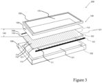
- Figure 3 shows an exploded view of a luminaire 200 comprising an acoustic lighting tile 100.
- the light guide panel 102 is shown to have a bottom surface 111 that is facing towards an acoustic panel 103 and a top surface 112 that is facing a light diffusing element 104.
- the light guide panel 102 has a rectangular perimeter defined by four edge surfaces 113, 116, and 121.
- the light guide panel 102 comprises a plurality of slits 14 separated by a plurality of light guide structures 115.
- the acoustic panel 103 is adapted to absorb at least a subset of sound waves that is incident and subsequently transmitted through the light guide panel 102.
- Figure 4 shows a simulation result of outcoupling light from a light guide panel 102 as shown in Figures 2 and 3 .
- the light guide panel 102 having two edge surfaces, a first edge surface 113 for incoupling light from a first light source 101 and a second edge surface 116 for incoupling light from a second light source 108.
- the light guide panel 102 has dimensions 570 mm by 570 mm, therefore a square.
- the maximum slit width, Wmax 12 mm of the plurality of slits 114 is located in the center, equidistance from the first edge surface 113 and the second edge surface 116.
- the distribution of the outcoupled light in the vertical direction, v, and the horizontal direction, h are shown in Figure 4 . It can be seen in this figure, that the distribution of outcoupled light have local intensity variations along the vertical direction, v, and the horizontal direction, h above the light guide panel 102.
- Figure 6 shows a simulation result of outcoupling light from the light guide panel with an enhanced distance between a light guide panel and a light-diffusing element.
- the (second) distance 109 between the light guide panel 102 and the light-diffusing element 104 is considered 50 mm.
Landscapes
- Engineering & Computer Science (AREA)
- Physics & Mathematics (AREA)
- General Engineering & Computer Science (AREA)
- General Physics & Mathematics (AREA)
- Optics & Photonics (AREA)
- Architecture (AREA)
- Multimedia (AREA)
- Acoustics & Sound (AREA)
- Civil Engineering (AREA)
- Structural Engineering (AREA)
- Electromagnetism (AREA)
- Planar Illumination Modules (AREA)
- Non-Portable Lighting Devices Or Systems Thereof (AREA)
Claims (14)
- Akustische Lichtkachel (100), umfassend:- eine erste Lichtquelle (101), die konfiguriert ist, um im Betrieb ein erstes Lichtquellenlicht bereitzustellen; und- eine Lichtleitplatte (102), die eine Unterseite (111), eine Oberseite (112) gegenüber der Unterseite (111) und eine erste Randfläche (113) umfasst, die sich zwischen der Unterseite (111) von der Oberseite (112) erstreckt, wobei die erste Randfläche (113) konfiguriert ist, um das erste Lichtquellenlicht von der ersten Lichtquelle (101) zu empfangen;dadurch gekennzeichnet, dass die Lichtleitplatte (102) eine Vielzahl von Lichtleitstrukturen (115) umfasst, die mindestens teilweise durch eine Vielzahl von Schlitzen (114) getrennt sind;wobei sich mindestens ein Teil jedes Schlitzes der Vielzahl von Schlitzen (114) zur ersten Randfläche (113) hin verjüngt, undwobei die akustische Lichtkachel (100) eine Akustikplatte (103) umfasst, die der Unterseite (111) der Lichtleitplatte (102) zugewandt ist, wobei die Akustikplatte (103) dazu geeignet ist, mindestens eine Teilmenge der auf die Lichtleitplatte (102) auftreffenden Schallwellen zu absorbieren.
- Akustische Lichtkachel (100) nach einem der vorstehenden Ansprüche, wobei jeder Schlitz der Vielzahl von Schlitzen (114) eine Hauptachse (117) aufweist, die im Wesentlichen parallel zueinander konfiguriert ist.
- Akustische Lichtkachel (100) nach einem der vorstehenden Ansprüche, wobei jeder der Vielzahl von Schlitzen (114) eine Schlitzlänge, Ls, aufweist und jede der Vielzahl von Lichtleiterstrukturen (115) eine Lichtleiterstrukturlänge, Lg, aufweist, die als ein Abstand von der ersten Kante (113) der Lichtleiterplatte (102) zu einem verjüngten Ende der Lichtleiterstruktur (115) definiert ist, und wobei 0,6*Lg < Ls < 0,98*Lg.
- Akustische Lichtkachel (100) nach einem der vorstehenden Ansprüche, wobei jeder Schlitz der Vielzahl von Schlitzen (114) eine maximale Schlitzbreite, Wmax, und eine minimale Schlitzbreite, Wmin, aufweist, wobei Wmax und/oder Wmin der Vielzahl von Schlitzen (114) in einem gleichen Abstand von der ersten Randfläche (113) angeordnet sind.
- Akustische Lichtkachel (100) nach einem der vorstehenden Ansprüche, wobei die akustische Lichtkachel (100) eine zweite Lichtquelle (108) umfasst, die angeordnet ist, um im Betrieb Licht einer zweiten Lichtquelle bereitzustellen, wobei die Lichtleitplatte (102) eine zweite Randfläche (116) gegenüber der ersten Randfläche (113) aufweist, wobei die zweite Randfläche (116) konfiguriert ist, um das zweite Lichtquellenlicht von der zweiten Lichtquelle (108) zu empfangen, und wobei sich mindestens ein Teil jedes Schlitzes der Vielzahl von Schlitzen (114) in Richtung der zweiten Randfläche (116) verjüngt.
- Akustische Lichtkachel (100) nach einem der vorstehenden Ansprüche, wobei die minimale Schlitzbreite, Wmin aus einem Bereich von 0,2 mm bis 2 mm ausgewählt ist und/oder wobei die maximale Schlitzbreite, Wmax aus einem Bereich von 3 mm bis 30 mm ausgewählt ist.
- Akustische Lichtkachel (100) nach einem der vorstehenden Ansprüche, wobei die Lichtleitplatte (102) eine Lichtleitplattenfläche, Ag, aufweist und die Vielzahl von Schlitzen (114) eine Schlitzfläche, Ao, aufweist und wobei Ao aus einem Bereich von 10 % bis 50 % von Ag ausgewählt ist.
- Akustische Lichtkachel (100) nach einem der vorstehenden Ansprüche, wobei die Lichtleitplatte (102) eine Vielzahl von Lichtauskopplungsmitteln auf der Unterseite (111) und/oder der Oberseite (112) umfasst.
- Akustische Lichtkachel (100) nach einem der vorstehenden Ansprüche, wobei jede der Vielzahl von Lichtleiterstrukturen (115) einen Querschnitt mit einer Form aufweist, die aus einer oder mehreren ausgewählt ist von einer polygonalen Form, einer runden Form und einer ovalen Form.
- Akustische Lichtkachel (100) nach einem der vorstehenden Ansprüche, wobei die Akustikplatte (103) eine der Unterseite (111) der Lichtleitplatte (102) zugewandte Außenfläche (131) umfasst, die lichtreflektierend ist.
- Akustische Lichtkachel (100) nach einem der vorstehenden Ansprüche, wobei die akustische Lichtkachel (100) ein lichtstreuendes Element (104) umfasst, das der Akustikplatte (103) zugewandt ist, wobei das lichtstreuende Element (104) dazu geeignet ist, mindestens eine Teilmenge von Schallwellen zu übertragen.
- Akustische Lichtkachel (100) nach einem der vorstehenden Ansprüche 1 bis 10, wobei die akustische Lichtkachel (100) ein lichtstreuendes Element (104) umfasst, das der oberen Oberfläche (112) der Lichtleitplatte (102) zugewandt ist, wobei das lichtstreuende Element (104) dazu geeignet ist, mindestens eine Teilmenge der auf die Lichtleitplatte (102) auftreffenden Schallwellen zu übertragen.
- Akustische Lichtkachel (100) nach einem der Ansprüche 11 bis 12, wobei das lichtstreuende Element (104) ein Vlies oder ein Gewebe ist.
- Leuchte (200), umfassend mindestens eine akustische Lichtkachel (100) nach einem der vorstehenden Ansprüche.
Applications Claiming Priority (2)
| Application Number | Priority Date | Filing Date | Title |
|---|---|---|---|
| EP21174234 | 2021-05-18 | ||
| PCT/EP2022/062560 WO2022243100A1 (en) | 2021-05-18 | 2022-05-10 | An acoustic lighting device |
Publications (2)
| Publication Number | Publication Date |
|---|---|
| EP4341603A1 EP4341603A1 (de) | 2024-03-27 |
| EP4341603B1 true EP4341603B1 (de) | 2025-07-09 |
Family
ID=76325325
Family Applications (1)
| Application Number | Title | Priority Date | Filing Date |
|---|---|---|---|
| EP22728488.2A Active EP4341603B1 (de) | 2021-05-18 | 2022-05-10 | Akustische beleuchtungsvorrichtung |
Country Status (4)
| Country | Link |
|---|---|
| US (1) | US12025290B1 (de) |
| EP (1) | EP4341603B1 (de) |
| CN (1) | CN117321333A (de) |
| WO (1) | WO2022243100A1 (de) |
Families Citing this family (2)
| Publication number | Priority date | Publication date | Assignee | Title |
|---|---|---|---|---|
| US12264802B2 (en) * | 2021-08-10 | 2025-04-01 | Turf Design, Inc. | Apparatus and system for lighting shroud system and methods thereof |
| KR102845423B1 (ko) * | 2025-05-27 | 2025-08-12 | 주식회사 펜타드 | 어쿠스틱 블록 |
Family Cites Families (12)
| Publication number | Priority date | Publication date | Assignee | Title |
|---|---|---|---|---|
| JP5511798B2 (ja) * | 2008-05-30 | 2014-06-04 | コーニンクレッカ フィリップス エヌ ヴェ | 光ガイドを有する照明装置 |
| EP2334981A1 (de) * | 2008-09-02 | 2011-06-22 | QUALCOMM MEMS Technologies, Inc. | Lichtdrehvorrichtung mit prismatischen lichtdrehenden eigenschaften |
| US9194124B2 (en) | 2011-12-09 | 2015-11-24 | 3M Innovative Properties Company | Acoustic light panel |
| KR102090457B1 (ko) * | 2012-12-05 | 2020-03-18 | 엘지디스플레이 주식회사 | 액정표시장치 |
| WO2014097042A1 (en) * | 2012-12-18 | 2014-06-26 | Koninklijke Philips N.V. | Sound absorbing lighting panel and modular surface system |
| CH708188A2 (de) * | 2013-05-29 | 2014-12-15 | Sonami Ag | Schalldämmplatte mit Leuchtmittel. |
| EP2821990A1 (de) * | 2013-07-02 | 2015-01-07 | Koninklijke Philips N.V. | System, umfassend eine Schalldämpfungsplatte |
| JP6067946B2 (ja) | 2013-11-18 | 2017-01-25 | フィリップス ライティング ホールディング ビー ヴィ | 音響照明タイル |
| DE202013105914U1 (de) | 2013-12-23 | 2015-03-24 | Zumtobel Lighting Gmbh | Leuchte |
| US11327356B2 (en) * | 2018-02-12 | 2022-05-10 | Nanocomp Oy Ltd | Light guide for segmented illumination |
| CN112313444B (zh) * | 2018-05-07 | 2022-09-13 | 昕诺飞控股有限公司 | 具有线性声音隔板的悬挂式光导照明装置 |
| CN112219061A (zh) | 2018-05-07 | 2021-01-12 | 昕诺飞控股有限公司 | 带有声音抑制的悬挂式垂饰光导灯具 |
-
2022
- 2022-05-10 WO PCT/EP2022/062560 patent/WO2022243100A1/en not_active Ceased
- 2022-05-10 CN CN202280036087.0A patent/CN117321333A/zh not_active Withdrawn
- 2022-05-10 US US18/288,396 patent/US12025290B1/en active Active
- 2022-05-10 EP EP22728488.2A patent/EP4341603B1/de active Active
Also Published As
| Publication number | Publication date |
|---|---|
| WO2022243100A1 (en) | 2022-11-24 |
| US20240210000A1 (en) | 2024-06-27 |
| CN117321333A (zh) | 2023-12-29 |
| US12025290B1 (en) | 2024-07-02 |
| EP4341603A1 (de) | 2024-03-27 |
Similar Documents
| Publication | Publication Date | Title |
|---|---|---|
| US9765516B2 (en) | Acoustically absorbing room divider | |
| EP4341603B1 (de) | Akustische beleuchtungsvorrichtung | |
| US5700527A (en) | Sound-absorbing glass building component or transparent synthetic glass building component | |
| US20190017260A1 (en) | Acoustic panel | |
| US10770053B2 (en) | Noise reducing lighting devices | |
| US10823393B2 (en) | LED illumination device with speaker function, and method for extracting light and sound from LED illumination device with speaker function | |
| JP2015504528A (ja) | 光音響パネル | |
| US10586525B1 (en) | Array of acoustical returner devices to reflect sound back in the incident direction | |
| CN112204300B (zh) | 吸声照明模块 | |
| AU762579B2 (en) | Light with a light-guiding element | |
| JP7291154B2 (ja) | 照明モジュール、キット及びパネル | |
| JP7231648B2 (ja) | 照明モジュール及び照明キット | |
| JP7246053B1 (ja) | 吸音パネル及び吸音壁 | |
| JP2024114238A (ja) | 吸音部材及び吸音壁 | |
| CA3007553A1 (en) | Acoustic panel | |
| HU223980B1 (hu) | Akusztikus felületelem és panel |
Legal Events
| Date | Code | Title | Description |
|---|---|---|---|
| STAA | Information on the status of an ep patent application or granted ep patent |
Free format text: STATUS: UNKNOWN |
|
| STAA | Information on the status of an ep patent application or granted ep patent |
Free format text: STATUS: THE INTERNATIONAL PUBLICATION HAS BEEN MADE |
|
| PUAI | Public reference made under article 153(3) epc to a published international application that has entered the european phase |
Free format text: ORIGINAL CODE: 0009012 |
|
| STAA | Information on the status of an ep patent application or granted ep patent |
Free format text: STATUS: REQUEST FOR EXAMINATION WAS MADE |
|
| 17P | Request for examination filed |
Effective date: 20231218 |
|
| AK | Designated contracting states |
Kind code of ref document: A1 Designated state(s): AL AT BE BG CH CY CZ DE DK EE ES FI FR GB GR HR HU IE IS IT LI LT LU LV MC MK MT NL NO PL PT RO RS SE SI SK SM TR |
|
| DAV | Request for validation of the european patent (deleted) | ||
| DAX | Request for extension of the european patent (deleted) | ||
| GRAP | Despatch of communication of intention to grant a patent |
Free format text: ORIGINAL CODE: EPIDOSNIGR1 |
|
| STAA | Information on the status of an ep patent application or granted ep patent |
Free format text: STATUS: GRANT OF PATENT IS INTENDED |
|
| INTG | Intention to grant announced |
Effective date: 20241218 |
|
| GRAS | Grant fee paid |
Free format text: ORIGINAL CODE: EPIDOSNIGR3 |
|
| P01 | Opt-out of the competence of the unified patent court (upc) registered |
Free format text: CASE NUMBER: APP_17871/2025 Effective date: 20250411 |
|
| GRAA | (expected) grant |
Free format text: ORIGINAL CODE: 0009210 |
|
| STAA | Information on the status of an ep patent application or granted ep patent |
Free format text: STATUS: THE PATENT HAS BEEN GRANTED |
|
| AK | Designated contracting states |
Kind code of ref document: B1 Designated state(s): AL AT BE BG CH CY CZ DE DK EE ES FI FR GB GR HR HU IE IS IT LI LT LU LV MC MK MT NL NO PL PT RO RS SE SI SK SM TR |
|
| REG | Reference to a national code |
Ref country code: GB Ref legal event code: FG4D |
|
| REG | Reference to a national code |
Ref country code: CH Ref legal event code: EP |
|
| REG | Reference to a national code |
Ref country code: IE Ref legal event code: FG4D |
|
| REG | Reference to a national code |
Ref country code: DE Ref legal event code: R096 Ref document number: 602022017332 Country of ref document: DE |
|
| REG | Reference to a national code |
Ref country code: NL Ref legal event code: MP Effective date: 20250709 |
|
| PG25 | Lapsed in a contracting state [announced via postgrant information from national office to epo] |
Ref country code: PT Free format text: LAPSE BECAUSE OF FAILURE TO SUBMIT A TRANSLATION OF THE DESCRIPTION OR TO PAY THE FEE WITHIN THE PRESCRIBED TIME-LIMIT Effective date: 20251110 |
|
| PG25 | Lapsed in a contracting state [announced via postgrant information from national office to epo] |
Ref country code: NL Free format text: LAPSE BECAUSE OF FAILURE TO SUBMIT A TRANSLATION OF THE DESCRIPTION OR TO PAY THE FEE WITHIN THE PRESCRIBED TIME-LIMIT Effective date: 20250709 |
|
| REG | Reference to a national code |
Ref country code: AT Ref legal event code: MK05 Ref document number: 1812097 Country of ref document: AT Kind code of ref document: T Effective date: 20250709 |
|
| PG25 | Lapsed in a contracting state [announced via postgrant information from national office to epo] |
Ref country code: IS Free format text: LAPSE BECAUSE OF FAILURE TO SUBMIT A TRANSLATION OF THE DESCRIPTION OR TO PAY THE FEE WITHIN THE PRESCRIBED TIME-LIMIT Effective date: 20251109 |
|
| PG25 | Lapsed in a contracting state [announced via postgrant information from national office to epo] |
Ref country code: NO Free format text: LAPSE BECAUSE OF FAILURE TO SUBMIT A TRANSLATION OF THE DESCRIPTION OR TO PAY THE FEE WITHIN THE PRESCRIBED TIME-LIMIT Effective date: 20251009 |
|
| REG | Reference to a national code |
Ref country code: LT Ref legal event code: MG9D |
|
| PG25 | Lapsed in a contracting state [announced via postgrant information from national office to epo] |
Ref country code: AT Free format text: LAPSE BECAUSE OF FAILURE TO SUBMIT A TRANSLATION OF THE DESCRIPTION OR TO PAY THE FEE WITHIN THE PRESCRIBED TIME-LIMIT Effective date: 20250709 |
|
| PG25 | Lapsed in a contracting state [announced via postgrant information from national office to epo] |
Ref country code: FI Free format text: LAPSE BECAUSE OF FAILURE TO SUBMIT A TRANSLATION OF THE DESCRIPTION OR TO PAY THE FEE WITHIN THE PRESCRIBED TIME-LIMIT Effective date: 20250709 |
|
| PG25 | Lapsed in a contracting state [announced via postgrant information from national office to epo] |
Ref country code: HR Free format text: LAPSE BECAUSE OF FAILURE TO SUBMIT A TRANSLATION OF THE DESCRIPTION OR TO PAY THE FEE WITHIN THE PRESCRIBED TIME-LIMIT Effective date: 20250709 |
|
| PG25 | Lapsed in a contracting state [announced via postgrant information from national office to epo] |
Ref country code: GR Free format text: LAPSE BECAUSE OF FAILURE TO SUBMIT A TRANSLATION OF THE DESCRIPTION OR TO PAY THE FEE WITHIN THE PRESCRIBED TIME-LIMIT Effective date: 20251010 |
|
| PG25 | Lapsed in a contracting state [announced via postgrant information from national office to epo] |
Ref country code: SE Free format text: LAPSE BECAUSE OF FAILURE TO SUBMIT A TRANSLATION OF THE DESCRIPTION OR TO PAY THE FEE WITHIN THE PRESCRIBED TIME-LIMIT Effective date: 20250709 |
|
| PG25 | Lapsed in a contracting state [announced via postgrant information from national office to epo] |
Ref country code: LV Free format text: LAPSE BECAUSE OF FAILURE TO SUBMIT A TRANSLATION OF THE DESCRIPTION OR TO PAY THE FEE WITHIN THE PRESCRIBED TIME-LIMIT Effective date: 20250709 |
|
| PG25 | Lapsed in a contracting state [announced via postgrant information from national office to epo] |
Ref country code: PL Free format text: LAPSE BECAUSE OF FAILURE TO SUBMIT A TRANSLATION OF THE DESCRIPTION OR TO PAY THE FEE WITHIN THE PRESCRIBED TIME-LIMIT Effective date: 20250709 Ref country code: BG Free format text: LAPSE BECAUSE OF FAILURE TO SUBMIT A TRANSLATION OF THE DESCRIPTION OR TO PAY THE FEE WITHIN THE PRESCRIBED TIME-LIMIT Effective date: 20250709 |
|
| PG25 | Lapsed in a contracting state [announced via postgrant information from national office to epo] |
Ref country code: RS Free format text: LAPSE BECAUSE OF FAILURE TO SUBMIT A TRANSLATION OF THE DESCRIPTION OR TO PAY THE FEE WITHIN THE PRESCRIBED TIME-LIMIT Effective date: 20251009 |
|
| PG25 | Lapsed in a contracting state [announced via postgrant information from national office to epo] |
Ref country code: ES Free format text: LAPSE BECAUSE OF FAILURE TO SUBMIT A TRANSLATION OF THE DESCRIPTION OR TO PAY THE FEE WITHIN THE PRESCRIBED TIME-LIMIT Effective date: 20250709 |
|
| PG25 | Lapsed in a contracting state [announced via postgrant information from national office to epo] |
Ref country code: SM Free format text: LAPSE BECAUSE OF FAILURE TO SUBMIT A TRANSLATION OF THE DESCRIPTION OR TO PAY THE FEE WITHIN THE PRESCRIBED TIME-LIMIT Effective date: 20250709 |
|
| PGFP | Annual fee paid to national office [announced via postgrant information from national office to epo] |
Ref country code: GB Payment date: 20260304 Year of fee payment: 5 |
|
| PG25 | Lapsed in a contracting state [announced via postgrant information from national office to epo] |
Ref country code: DK Free format text: LAPSE BECAUSE OF FAILURE TO SUBMIT A TRANSLATION OF THE DESCRIPTION OR TO PAY THE FEE WITHIN THE PRESCRIBED TIME-LIMIT Effective date: 20250709 |
|
| PG25 | Lapsed in a contracting state [announced via postgrant information from national office to epo] |
Ref country code: IT Free format text: LAPSE BECAUSE OF FAILURE TO SUBMIT A TRANSLATION OF THE DESCRIPTION OR TO PAY THE FEE WITHIN THE PRESCRIBED TIME-LIMIT Effective date: 20250709 |
|
| PG25 | Lapsed in a contracting state [announced via postgrant information from national office to epo] |
Ref country code: CZ Free format text: LAPSE BECAUSE OF FAILURE TO SUBMIT A TRANSLATION OF THE DESCRIPTION OR TO PAY THE FEE WITHIN THE PRESCRIBED TIME-LIMIT Effective date: 20250709 |
|
| PG25 | Lapsed in a contracting state [announced via postgrant information from national office to epo] |
Ref country code: SK Free format text: LAPSE BECAUSE OF FAILURE TO SUBMIT A TRANSLATION OF THE DESCRIPTION OR TO PAY THE FEE WITHIN THE PRESCRIBED TIME-LIMIT Effective date: 20250709 Ref country code: EE Free format text: LAPSE BECAUSE OF FAILURE TO SUBMIT A TRANSLATION OF THE DESCRIPTION OR TO PAY THE FEE WITHIN THE PRESCRIBED TIME-LIMIT Effective date: 20250709 |