EP4341987B1 - Energiesparende wärmebehandlungsvorrichtung für metallsubstrat in korrosivem gas - Google Patents
Energiesparende wärmebehandlungsvorrichtung für metallsubstrat in korrosivem gas Download PDFInfo
- Publication number
- EP4341987B1 EP4341987B1 EP22942950.1A EP22942950A EP4341987B1 EP 4341987 B1 EP4341987 B1 EP 4341987B1 EP 22942950 A EP22942950 A EP 22942950A EP 4341987 B1 EP4341987 B1 EP 4341987B1
- Authority
- EP
- European Patent Office
- Prior art keywords
- substrate
- heat treatment
- energy
- treatment device
- corrosive gas
- Prior art date
- Legal status (The legal status is an assumption and is not a legal conclusion. Google has not performed a legal analysis and makes no representation as to the accuracy of the status listed.)
- Active
Links
Images



Classifications
-
- H—ELECTRICITY
- H10—SEMICONDUCTOR DEVICES; ELECTRIC SOLID-STATE DEVICES NOT OTHERWISE PROVIDED FOR
- H10P—GENERIC PROCESSES OR APPARATUS FOR THE MANUFACTURE OR TREATMENT OF DEVICES COVERED BY CLASS H10
- H10P72/00—Handling or holding of wafers, substrates or devices during manufacture or treatment thereof
- H10P72/04—Apparatus for manufacture or treatment
- H10P72/0431—Apparatus for thermal treatment
- H10P72/0436—Apparatus for thermal treatment mainly by radiation
-
- B—PERFORMING OPERATIONS; TRANSPORTING
- B01—PHYSICAL OR CHEMICAL PROCESSES OR APPARATUS IN GENERAL
- B01D—SEPARATION
- B01D39/00—Filtering material for liquid or gaseous fluids
- B01D39/14—Other self-supporting filtering material ; Other filtering material
- B01D39/20—Other self-supporting filtering material ; Other filtering material of inorganic material, e.g. asbestos paper, metallic filtering material of non-woven wires
- B01D39/2068—Other inorganic materials, e.g. ceramics
-
- B—PERFORMING OPERATIONS; TRANSPORTING
- B01—PHYSICAL OR CHEMICAL PROCESSES OR APPARATUS IN GENERAL
- B01D—SEPARATION
- B01D46/00—Filters or filtering processes specially modified for separating dispersed particles from gases or vapours
- B01D46/0002—Casings; Housings; Frame constructions
- B01D46/0005—Mounting of filtering elements within casings, housings or frames
-
- F—MECHANICAL ENGINEERING; LIGHTING; HEATING; WEAPONS; BLASTING
- F27—FURNACES; KILNS; OVENS; RETORTS
- F27B—FURNACES, KILNS, OVENS OR RETORTS IN GENERAL; OPEN SINTERING OR LIKE APPARATUS
- F27B17/00—Furnaces of a kind not covered by any of groups F27B1/00 - F27B15/00
- F27B17/0016—Chamber type furnaces
- F27B17/0025—Chamber type furnaces specially adapted for treating semiconductor wafers
-
- F—MECHANICAL ENGINEERING; LIGHTING; HEATING; WEAPONS; BLASTING
- F27—FURNACES; KILNS; OVENS; RETORTS
- F27B—FURNACES, KILNS, OVENS OR RETORTS IN GENERAL; OPEN SINTERING OR LIKE APPARATUS
- F27B17/00—Furnaces of a kind not covered by any of groups F27B1/00 - F27B15/00
- F27B17/0016—Chamber type furnaces
- F27B17/0083—Chamber type furnaces with means for circulating the atmosphere
-
- F—MECHANICAL ENGINEERING; LIGHTING; HEATING; WEAPONS; BLASTING
- F27—FURNACES; KILNS; OVENS; RETORTS
- F27D—DETAILS OR ACCESSORIES OF FURNACES, KILNS, OVENS OR RETORTS, IN SO FAR AS THEY ARE OF KINDS OCCURRING IN MORE THAN ONE KIND OF FURNACE
- F27D11/00—Arrangement of elements for electric heating in or on furnaces
- F27D11/08—Heating by electric discharge, e.g. arc discharge
-
- F—MECHANICAL ENGINEERING; LIGHTING; HEATING; WEAPONS; BLASTING
- F27—FURNACES; KILNS; OVENS; RETORTS
- F27D—DETAILS OR ACCESSORIES OF FURNACES, KILNS, OVENS OR RETORTS, IN SO FAR AS THEY ARE OF KINDS OCCURRING IN MORE THAN ONE KIND OF FURNACE
- F27D25/00—Devices or methods for removing incrustations, e.g. slag, metal deposits, dust; Devices or methods for preventing the adherence of slag
- F27D25/008—Devices or methods for removing incrustations, e.g. slag, metal deposits, dust; Devices or methods for preventing the adherence of slag using fluids or gases, e.g. blowers, suction units
-
- H—ELECTRICITY
- H10—SEMICONDUCTOR DEVICES; ELECTRIC SOLID-STATE DEVICES NOT OTHERWISE PROVIDED FOR
- H10F—INORGANIC SEMICONDUCTOR DEVICES SENSITIVE TO INFRARED RADIATION, LIGHT, ELECTROMAGNETIC RADIATION OF SHORTER WAVELENGTH OR CORPUSCULAR RADIATION
- H10F71/00—Manufacture or treatment of devices covered by this subclass
- H10F71/128—Annealing
-
- H—ELECTRICITY
- H10—SEMICONDUCTOR DEVICES; ELECTRIC SOLID-STATE DEVICES NOT OTHERWISE PROVIDED FOR
- H10F—INORGANIC SEMICONDUCTOR DEVICES SENSITIVE TO INFRARED RADIATION, LIGHT, ELECTROMAGNETIC RADIATION OF SHORTER WAVELENGTH OR CORPUSCULAR RADIATION
- H10F77/00—Constructional details of devices covered by this subclass
- H10F77/10—Semiconductor bodies
- H10F77/12—Active materials
- H10F77/126—Active materials comprising only Group I-III-VI chalcopyrite materials, e.g. CuInSe2, CuGaSe2 or CuInGaSe2 [CIGS]
-
- H—ELECTRICITY
- H10—SEMICONDUCTOR DEVICES; ELECTRIC SOLID-STATE DEVICES NOT OTHERWISE PROVIDED FOR
- H10P—GENERIC PROCESSES OR APPARATUS FOR THE MANUFACTURE OR TREATMENT OF DEVICES COVERED BY CLASS H10
- H10P72/00—Handling or holding of wafers, substrates or devices during manufacture or treatment thereof
- H10P72/04—Apparatus for manufacture or treatment
- H10P72/0451—Apparatus for manufacturing or treating in a plurality of work-stations
- H10P72/0462—Apparatus for manufacturing or treating in a plurality of work-stations characterised by the construction of the processing chambers, e.g. modular processing chambers
-
- H—ELECTRICITY
- H10—SEMICONDUCTOR DEVICES; ELECTRIC SOLID-STATE DEVICES NOT OTHERWISE PROVIDED FOR
- H10P—GENERIC PROCESSES OR APPARATUS FOR THE MANUFACTURE OR TREATMENT OF DEVICES COVERED BY CLASS H10
- H10P72/00—Handling or holding of wafers, substrates or devices during manufacture or treatment thereof
- H10P72/70—Handling or holding of wafers, substrates or devices during manufacture or treatment thereof for supporting or gripping
- H10P72/76—Handling or holding of wafers, substrates or devices during manufacture or treatment thereof for supporting or gripping using mechanical means, e.g. clamps or pinches
- H10P72/7604—Handling or holding of wafers, substrates or devices during manufacture or treatment thereof for supporting or gripping using mechanical means, e.g. clamps or pinches the wafers being placed on a susceptor, stage or support
- H10P72/7622—Handling or holding of wafers, substrates or devices during manufacture or treatment thereof for supporting or gripping using mechanical means, e.g. clamps or pinches the wafers being placed on a susceptor, stage or support characterised by supporting substrates others than wafers, e.g. chips
-
- H—ELECTRICITY
- H10—SEMICONDUCTOR DEVICES; ELECTRIC SOLID-STATE DEVICES NOT OTHERWISE PROVIDED FOR
- H10P—GENERIC PROCESSES OR APPARATUS FOR THE MANUFACTURE OR TREATMENT OF DEVICES COVERED BY CLASS H10
- H10P72/00—Handling or holding of wafers, substrates or devices during manufacture or treatment thereof
- H10P72/70—Handling or holding of wafers, substrates or devices during manufacture or treatment thereof for supporting or gripping
- H10P72/76—Handling or holding of wafers, substrates or devices during manufacture or treatment thereof for supporting or gripping using mechanical means, e.g. clamps or pinches
- H10P72/7604—Handling or holding of wafers, substrates or devices during manufacture or treatment thereof for supporting or gripping using mechanical means, e.g. clamps or pinches the wafers being placed on a susceptor, stage or support
- H10P72/7624—Handling or holding of wafers, substrates or devices during manufacture or treatment thereof for supporting or gripping using mechanical means, e.g. clamps or pinches the wafers being placed on a susceptor, stage or support characterised by the mechanical construction of the susceptor, stage or support
-
- H—ELECTRICITY
- H10—SEMICONDUCTOR DEVICES; ELECTRIC SOLID-STATE DEVICES NOT OTHERWISE PROVIDED FOR
- H10P—GENERIC PROCESSES OR APPARATUS FOR THE MANUFACTURE OR TREATMENT OF DEVICES COVERED BY CLASS H10
- H10P95/00—Generic processes or apparatus for manufacture or treatments not covered by the other groups of this subclass
- H10P95/90—Thermal treatments, e.g. annealing or sintering
-
- F—MECHANICAL ENGINEERING; LIGHTING; HEATING; WEAPONS; BLASTING
- F27—FURNACES; KILNS; OVENS; RETORTS
- F27D—DETAILS OR ACCESSORIES OF FURNACES, KILNS, OVENS OR RETORTS, IN SO FAR AS THEY ARE OF KINDS OCCURRING IN MORE THAN ONE KIND OF FURNACE
- F27D99/00—Subject matter not provided for in other groups of this subclass
- F27D99/0001—Heating elements or systems
- F27D99/0006—Electric heating elements or system
- F27D2099/0026—Electric heating elements or system with a generator of electromagnetic radiations
Definitions
- the present invention relates to the technical field of rapid heat treatment of metal substrates, AND to an energy-saving heat treatment device for a metal substrate in a corrosive gas.
- a process box consists of a graphite or composite frame such as carbon fiber reinforced carbon (CFRC), reinforced carbon (RCC) or carbon fiber-carbon composite (CFC). Glass ceramic tiles have been shown to be resistant to high temperatures, insensitive to temperature gradients and to corrosion by selenium or sulfur, very low coefficient of expansion and high mechanical stability. Due to use of each 4 mm thick board alone, the mass of the boards is already four times that of the substrate. For a substrate with an area of about 1 m 2 (equivalent to 5kg in a case of a thickness of 2 mm), the total weight of the box is about 40 kg. This "non-productive" substance is eventually heated to process temperature and must then be cooled again during the process.
- CFRC carbon fiber reinforced carbon
- CFC carbon fiber-carbon composite
- EP1258043 selection box
- EP1277238 chamber structure of selection facility
- graphite films are described as energy transmitters in EP1258043
- the main claim always assumes a transparent body, especially a glass ceramic. Therefore, the energy transmitter is an additional layer or film that does not act as a cover or floor for a box.
- EP1258043 selection box
- EP1277238 chamber structure of selection facility
- graphite films are described as energy transmitters in EP1258043
- the main claim always assumes a transparent body, especially a glass ceramic. Therefore, the energy transmitter is an additional layer or film that does not act as a cover or floor for a box.
- the substrate is moved on rolls or in a process chamber (a chamber or a continuous channel).
- the gaseous selenium must be injected into a relatively large chamber (with conveying rollers) to generate the necessary selenium vapor pressure.
- CIGS/CIGSSE thin-film semiconductors and thin-film modules with similar efficiencies have not been produced according to these methods in large-scale production or in the laboratory.
- the consumption of chalcogens is usually very high because chalcogens are basically not limited to small processing quantities. This also increases the problem of deposits and corrosion.
- One of the objectives of the present invention is to overcome the above-mentioned deficiencies of the prior art, and to provide an energy-saving heat treatment device for a metal substrate in a corrosive gas. Its core is to make a further development in the existing AVANCIS program, so that the modified process frame has the advantages of no corrosion on the edge of the substrate during processing, high efficiency and low energy consumption and can effectively solve the problem that an IG or semiconductor stack cannot be produced on a metal substrate currently.
- the process frame is made on the basis of the modification to the structure of the original process frame.
- the edge By covering the outer edge of the substrate, the edge can be protected from contact with selenium, and moreover chalcogen elements in contact with the edge can be reduced, and even residual chalcogen elements or hydrocarbons in the chamber will not corrode the edge of the substrate. Since the process space is minimized, the chalcogenide elements in the process chamber are greatly reduced, and a barrier layer on a bottom side of the substrate can also be significantly thinned.
- the term "radiation field” refers to a heated space formed by the heating radiation of an energy source in an RTP process, for example, a radiation source with transparent walls, such as a lamp.
- An object to be treated is placed in the chamber and irradiated with radiation from a radiation source, and then the object can be heated.
- a chamber with transparent walls is not absolutely necessary in the system, as long as the system controls an atmosphere in which the object is placed during treatment.
- process space refers to the space in which the substrate is processed by the RTP process. Specifically, the above-mentioned space is the space in which the process frame covers the substrate in the radiation field.
- the two methods for covering the edge of the lower surface respectively correspond to covering by the process frame itself and covering by the bottom surface of the radiation field being in contact with the substrate.
- the substrate and the process frame are in plug-in fit, and the contact area between the edge of the substrate and the process frame is large, so the substrate and the process frame are fixed more securely; and in Mode II), the process frame does not have a bottom plate, so the overall structure of the process frame more simple.
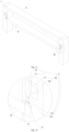
- 1 process frame; 2. substrate; 3. cover; 4. bottom plate; 5. sealing member; 6. gap; 7. hollow body; 11. accommodating space; 41. first transmission plate; 42. second transmission plate; 43. spacer; 44. first spring; 45. second spring; 46, gas storage space; 71. inner metal wall; 72. cavity; 73. first filler; 74. gas passage; 75. chalcogenide filter; 76. desulfurization space; 77. second filler; 411. vent hole.
- FIG 1 and FIG 2 The energy-saving heat treatment device for a metal substrate in a corrosive gas is shown in FIG 1 and FIG 2 according to an embodiment of the present invention.
- the substrate 2 i.e., a steel plate or a foil
- the process frame 1 is inserted into the process frame 1 to protect its edges from contact with selenium. Therefore, the parts of the process frame 1 must cover its surface and the lower surface of the substrate 2, the process frame 1 forms an open area, and evaporated chalcogen or additional H 2 S will affect the open area.
- the edge of the lower surface of the substrate (2) is covered by two methods:
- the smallest process space for the substrate 2 is formed by the process frame 1, the cover 3 and the substrate 2.
- the cover 3 is configured on the process frame 1 and forms, together with the process frame 1 and the substrate 2, a gas shielding space for isolate the gas within the radiation field.
- the cover functions as a cover for the process frame, and the cover is inserted in or placed on the process frame (see Figs, 3 and 4 ).
- the cover remains on the process frame, and the process frame and the cover are converted into a process space with reduced volume through vertical translation.
- Fig. 3 shows the variable in the case of no bottom plate
- Fig. 4 shows the variable in the case of a bottom plate provided.
- Figure 4 can also show the case where the process frame is placed on the bottom plate.
- cover 3 is configured as:
- a bottom plate 4 for supporting the substrate 2 and preventing the substrate 2 from being corroded by a corrosive gas is configured below the substrate 2.
- the bottom plate 4 further development is made on the basis of the structure of the process frame 1.
- the above-mentioned process frame 1 with the substrate 2 and the cover 3 can already form the smallest process space. That is, with regard to chalcogenide control, the bottom plate 4 is no longer required, and the elimination of the bottom plate 4 also has the advantage of significantly reducing the thermal mass, in addition to reducing the asymmetry of heating.
- the state-of-the-art technology of the process frame 1 achieves heat supply from above only by radiation (radiation of a heat sink and the cover heated indirectly by the heat sink).
- the heat from below is partly conducted by the physical contact between the bottom plate 4 and the substrate 2, and partly by thermal radiation, and this leads to complex time dynamic changes, which can only be partially compensated by the different current radiations from the above and the below.
- the process frame 1 and the bottom plate 4 are of a separate configuration structure, specifically in two forms as follows;
- the substrate 2 is always smaller than the box frame.
- the present invention adopts the following ways to insert the substrate 2 into the process frame 1.
- the process frame 1 is composed of at least two separable parts. In this case, the process frame 1 is composed of at least two separable parts.
- the bottom plate 2 is inserted or placed in a lower frame, and an upper frame protects and covers the edge area of the upper surface of the bottom plate 2.
- an upper frame protects and covers the edge area of the upper surface of the bottom plate 2.
- the process frame 1 has a bottom plate 4, on which the substrate 2 is laid.
- the process frame 1 is installed on the bottom plate 4.
- the bottom plate 4 and the process frame 1 comprehensively protect and cover the edge area of the substrate 2.
- the bottom plate 4 can be improved as follows.
- the bottom plate 4 is supported by external rods on the load frame and the following possibilities are described for the external rods.
- the mechanical clamping film can also be used as the bottom plate of the process frame to stimulate and support the substrate.
- Stimulation by an external wire mesh is also allowed.
- the bottom plate 4 is composed of a plurality of support rods.
- a sealing member 5 in order to ensure that the gas shielding space has good sealing performance even in the event of mechanical deformation or thermal expansion of the process frame 1, and then the size of a sealing member 5 should ensure that the gas shielding space remains in a cold state, which helps to draw away residual water vapor or oxygen. When heated, the sealing member 5 expands more than the process frame 1 and closes a gap 6 between the substrate 2 and the process frame 1.
- examples of material combinations for the above structure graphite box frame (with an extension coefficient of 2x10 -6 K -1 ) or CFK (0.5x10 -6 K -1 perpendicular to the fibers); sealing member 5: glass-ceramic with an expansion coefficient of 9x10 -6 K -1 , zirconium oxide (10-13x10 -6 K -1 ), and magnesium oxide.
- the sealing member has a thickness of 5mm, a temperature difference of 400K, and a length difference of about 0.1mm. Considering that the steel substrate also expands with an expansion coefficient of 11-13x10 -6 K -1 , the width of the gap 6 in the cold state can be chosen to be slightly larger.
- the existing structure can be improved to automatically remove the chalcogen gas.
- a hollow body 7 is formed above or below the gap 6.
- the hollow body 7 is composed of an inner metal wall 71 and a cavity 72.
- the inner metal wall 71 is configured to conduct the heat of the radiation field and the process frame 1 to the first filler 73 and to form a desulfurization space 76.
- a first filler 73 shrinking with the temperature rise of the inner metal wall 71 after absorbing the heat is arranged at a connection opening between the cavity 72 and the gap 6 and shrinks along with the first filler 73 to form a gas passage 74 by which the gap 6 and the cavity 72 come into communication.
- the first filler 73 has a shrunken tip, and the tip of the first filler 73 is located at the connection opening. During the shrinking process, no matter whether the tip of the first filler 73 shrinks radially or laterally, the gas passage 74 can come into communication faster.
- ceramic fibers are used as the first filler 73, and the ceramic fiber material has excellent thermal shrinkage properties, so as to achieve the purpose of rapidly opening the gas passage 74 at a high temperature.
- a chalcogen filtering structure in order to better filter the chalcogen elements in the gas, a chalcogen filtering structure is designed.
- the preliminary filtering structure adopts a chalcogen filter
- the chalcogen filter is configured to filter the chalcogen elements on the gas passage 74 and is arranged on the gas passage 74 to achieve the purpose of filtering the chalcogen elements in the gas entering the cavity 72 to implement the primary filtration of the chalcogen elements.
- a secondary filtering structure is configured as a desulfurization space 76.
- the desulfurization space 76 stores desulfurization gas therein and is arranged between the cavity 72 and the inner metal wall 71.
- gas is desulfurized by the desulfurization gas in the desulfurization space 76 to reduce the chalcogen elements in the gas in the gap 6 and the desulfurization space 76.
- the desulfurization gas is an alkaline gas, and preferably, the alkaline gas may be ammonia gas.
- a second filler 77 that expands as the temperature rises is configured to form, in the desulfurization space 76, a piston structure for pushing the desulfurization gas out.
- the desulfurization space 76 is in a degassed state after being heated, so that the desulfurization gas enters the gap 6, and after the gas passage comes into communication, the desulfurization spaces 76 on two sides form a structure similar to a syringe under the action of the inner metal wall 71 and the second filler 77, so as to implement the push-out action of the desulfurization gas.
- the second filler 77 includes a heat-conducting balloon and a thermally expandable fluid. Since the thermally expandable fluid is very common, it will not be described in detail herein.
- the heat-conducting balloon is made of a heat-resistant material.
- the fluid in combination with the heat-conducting balloon forms a thermal deformation structure that is likely to expand and shrink with temperature.
- the thermal deformation structure has a long service life.
- the second filler 77 is hardly damaged during thermal deformation.
- the second filler can also be of a solid structure that expands by heat. Since the solid material that expands by heat is relatively common, the present invention will not describe the material in detail.
- a limit space for the first filler 73 to move linearly is formed between one side of the inner metal wall 71 and the inner wall of the cavity 72, and the desulfurization space 76 is located on the other side of the inner metal wall 71.
- the inner metal wall 71 is an accessory with good thermal conductivity. On the one hand, during the heating process, the inner metal wall 71 can better conduct heat to the first filler 73.
- the first filler 73 and the second filler 77 are restricted to shrink in a linear direction, so as to better separate the first filler 73 from the connection opening.
- the gas passage 74 is sequentially provided with an inlet section, a convergent section, a throat and a diffusion section along an inlet direction to form a Venturi tube type gas passage 74 that is easy for the gas to flow into the gap 6 from the cavity 72.
- the bottom plate 4 is of a structure that is not easily subjected to stress and fracturing, thus ensuring the mechanical strength of the bottom plate 4.
- the present invention makes the following improvements to the bottom plate 4.
- the bottom plate 4 includes: a first transmission plate 41, a second transmission plate 42, a spacer 43, a first spring 44, and a second spring 45.
- the spacer 43 may be a part of the process frame 1.
- the spacer 43 is configured to separate the first transmission plate 41 from the second transmission plate 42 and arranged on a peripheral edge of the first transmission plate 41 and a peripheral edge of the second transmission plate 42.
- the first spring 44 is arranged between a bottom surface of the first transmission plate 41 and the spacer 43 to form a first expansion space.
- the second spring 45 is arranged between a top surface of the second transmission plate 42 and the spacer 43 to form a second expansion space.
- the first spring 44 is located at a position adjacent to the peripheral edge of the first transmission plate 41
- the second spring 45 is located at a position adjacent to the peripheral edge of the second transmission plate 42.
- an expansion space is formed between the first transmission plate 41 and the spacer 43 and between the second transmission plate 42 and the spacer 43, so as to prevent the thermally expanded first transmission plate 41 or second transmission plate 42 from fracturing due to the narrowed space.
- each of the first spring 44 and the second spring 45 includes a superalloy.
- the superalloy includes cobalt, chromium, nickel, and molybdenum.
- the superalloy is selected because the superalloy is non-magnetic, presents high strength, and maintains excellent formability, excellent corrosion resistance and high fatigue strength.
- the chalcogenide gas can be prevented from corroding the two springs in the expansion spaces.
- the service life of the superalloy is relatively long, the actual service life of the bottom plate 4 is prolonged.
- the first spring 44 includes a coil spring, and the coil spring is in contact with the bottom surface of the first transmission plate 41 adjacent to the peripheral edge of the first transmission plate 41;
- the second spring 45 includes a coil spring, and the coil spring is in contact with the top surface of the second transfer plate 42 adjacent to the peripheral edge of the second transmission plate 42.
- first transmission plate 41 and the second transmission plate 42 are each provided with a plurality of vent holes 411 for gas to pass into the gas storage space.
Landscapes
- Engineering & Computer Science (AREA)
- General Engineering & Computer Science (AREA)
- Mechanical Engineering (AREA)
- Chemical & Material Sciences (AREA)
- Chemical Kinetics & Catalysis (AREA)
- Geology (AREA)
- Life Sciences & Earth Sciences (AREA)
- Inorganic Chemistry (AREA)
- Ceramic Engineering (AREA)
- Chemical Vapour Deposition (AREA)
- Health & Medical Sciences (AREA)
- Toxicology (AREA)
- Furnace Charging Or Discharging (AREA)
- Container, Conveyance, Adherence, Positioning, Of Wafer (AREA)
- Physical Or Chemical Processes And Apparatus (AREA)
Claims (17)
- Energiesparende Wärmebehandlungsvorrichtung für ein Metallsubstrat in einem korrosiven Gas, die Folgendes umfasst:eine Prozesskammer;ein Strahlungsfeld, das in einem Prozessraum angeordnet ist, um eine Wärmequelle für den Prozessraum bereitzustellen;einen Prozessrahmen (1), der innerhalb des Prozessraums angeordnet ist, um mindestens ein Substrat (2) aufzunehmen, um einen schnellen Wärmebehandlungsprozess durchzuführen, wobei eine obere Fläche einer Außenkante des Substrats (2) auf dem Prozessrahmen (1) abgedeckt ist; undeine Abdeckung (3), die eine Oberseite des Prozessrahmens (1) abdeckt, um einen Raum über dem Substrat (2) von der Prozesskammer zu isolieren;wobei der Prozessrahmen (1), das Substrat (2) und die Abdeckung (3) ein kleines Prozessvolumen bilden, und das kleine Prozessvolumen eine Menge an Einleitung und/oder Überlauf eines mit der Prozesskammer ausgetauschten Prozessgases auf einen Grenzwert reduziert;wobei die Abdeckung (3) wie folgt ausgebildet ist:1) sie befindet sich innerhalb des Strahlungsfeldes und bleibt stationär; oder2) sie befindet sich auf dem Prozessrahmen (1) und bildet eine integrale Struktur mit dem Prozessrahmen (1);wobei die Außenkante der unteren Fläche des Substrats (2) durch zwei Verfahren abgedeckt wird:Modus I): der Prozessrahmen (1) deckt die Außenkante der unteren Fläche des Substrats (2) ab; oderModus II) das Substrat (2) steht in Kontakt mit einer Bodenfläche des Strahlungsfeldes, so dass die Bodenfläche des Strahlungsfeldes die Bodenfläche des Substrats (2) abdeckt;wobeidie Abdeckung (3) sich zwischen den beiden Außenkanten des Substrats (2) befindet, ein Abdeckbereich der Abdeckung (3) in einem Bereich von 1 bis 50 mm liegt, und die Abdeckung (3) mit einem photoelektrisch inerten Material versehen ist;wobei Modus II) Folgendes umfasst:
eine Bodenplatte (4) ist unter dem Substrat (2) in zwei Formen angeordnet:Form a): die Bodenplatte (4) trägt das Substrat (2) und befindet sich an einem unteren Ende des Prozessrahmens (1) und bildet eine integrale Struktur mit dem Prozessrahmen (1); undForm b): die Bodenplatte (4) trägt das Substrat (2) und ist auf der Bodenfläche des Strahlungsfeldes installiert; undwobei in der Außenkante des Substrats (2) ein Dichtungselement (5) zum Abdichten einer oberen Fläche und/oder einer unteren Fläche der Außenkante des Substrats (2) angeordnet ist. - Energiesparende Wärmebehandlungsvorrichtung für ein Metallsubstrat in einem korrosiven Gas nach Anspruch 1, wobei das Dichtungselement (5) ein Material umfasst, das einen Längsausdehnungskoeffizienten aufweist, der größer ist als der des Prozessrahmens (1), und das Dichtungselement (5), der Prozessrahmen (1) und das Substrat (2) im kalten Zustand einen Spalt (6) bilden.
- Energiesparende Wärmebehandlungsvorrichtung für ein Metallsubstrat in einem korrosiven Gas nach Anspruch 2, wobei das Dichtungselement (5) mindestens eines oder eine Kombination aus Glaskeramik, Zirconiumoxid und Magnesiumoxid umfasst.
- Energiesparende Wärmebehandlungsvorrichtung für ein Metallsubstrat in einem korrosiven Gas nach Anspruch 3, wobei ein Metalldrahtgeflecht auf der unteren Fläche des Substrats (2) und im Wesentlichen parallel zum Substrat (2) angeordnet ist.
- Energiesparende Wärmebehandlungsvorrichtung für ein Metallsubstrat in einem korrosiven Gas nach Anspruch 4, wobei die Bodenplatte (4) mindestens eine Stützstange umfasst.
- Energiesparende Wärmebehandlungsvorrichtung für ein Metallsubstrat in einem korrosiven Gas nach Anspruch 4, wobei die Bodenplatte (4) Folgendes umfasst:eine erste Übertragungsplatte (41);eine zweite Übertragungsplatte (42);einen Abstandshalter (43), der so ausgebildet ist, dass er die erste Übertragungsplatte (41) von der zweiten Übertragungsplatte (42) trennt, und an einer Umfangskante der ersten Übertragungsplatte (41) und einer Umfangskante der zweiten Übertragungsplatte (42) angeordnet ist;eine erste Feder (44), die zwischen einer Bodenfläche der ersten Übertragungsplatte (41) und dem Abstandshalter (43) angeordnet ist; undeine zweite Feder (45), die zwischen einer Oberseitenfläche der zweiten Übertragungsplatte (42) und dem Abstandshalter (43) angeordnet ist.
- Energiesparende Wärmebehandlungsvorrichtung für ein Metallsubstrat in einem korrosiven Gas nach Anspruch 6, wobei sich die erste Feder (44) an einer Position angrenzend an die Umfangskante der ersten Übertragungsplatte (41) befindet, und die zweite Feder (45) sich an einer Position angrenzend an die Umfangskante der zweiten Übertragungsplatte (42) befindet.
- Energiesparende Wärmebehandlungsvorrichtung für ein Metallsubstrat in einem korrosiven Gas nach Anspruch 7, wobei jede der ersten Feder (44) und der zweiten Feder (45) eine Superlegierung umfasst;
wobei die Superlegierung Kobalt, Chrom, Nickel und Molybdän umfasst. - Energiesparende Wärmebehandlungsvorrichtung für ein Metallsubstrat in einem korrosiven Gas nach Anspruch 8, wobei die erste Übertragungsplatte (41) mit einer Vielzahl von Entlüftungslöchern (411) für das Passieren von Gas versehen ist.
- Energiesparende Wärmebehandlungsvorrichtung für ein Metallsubstrat in einem korrosiven Gas nach Anspruch 8, wobei die erste Feder (44) eine Schraubenfeder umfasst und die Schraubenfeder in Kontakt mit der Bodenfläche der ersten Übertragungsplatte (41) steht, die an die Umfangskante der ersten Übertragungsplatte (41) angrenzt; die zweite Feder (45) eine Schraubenfeder umfasst und die Schraubenfeder in Kontakt mit der Oberseitenfläche der zweiten Übertragungsplatte steht, die an die Umfangskante der zweiten Übertragungsplatte (42) angrenzt.
- Energiesparende Wärmebehandlungsvorrichtung für ein Metallsubstrat in einem korrosiven Gas nach Anspruch 10, wobei der Spalt (6) Folgendes umfasst:
einen Hohlkörper (7), der auf einer Oberseitenfläche und/oder einer Bodenfläche des Spalts (6) positioniert ist, wobei der Hohlkörper (7) als innere Metallwand (71) und ein Hohlraum (72) ausgeführt ist, wobei ein erster Füllstoff (73) angeordnet ist, um eine Verbindungsöffnung zwischen dem Hohlraum (72) und dem Spalt (6) in dem Hohlraum (72) zu blockieren, wobei der erste Füllstoff (73) schrumpft und die Verbindungsöffnung öffnet, wenn die Temperatur steigt. - Energiesparende Wärmebehandlungsvorrichtung für ein Metallsubstrat in einem korrosiven Gas nach Anspruch 11, wobei der erste Füllstoff (73) eine geschrumpfte Spitze aufweist und die Spitze des ersten Füllstoffs (73) sich an der Verbindungsöffnung befindet.
- Energiesparende Wärmebehandlungsvorrichtung für ein Metallsubstrat in einem korrosiven Gas nach Anspruch 12, wobei der erste Füllstoff (73) Keramikfasern umfasst; wobei an der Verbindungsöffnung ein Chalkogenidfilter (75) ausgebildet ist;
- Energiesparende Wärmebehandlungsvorrichtung für ein Metallsubstrat in einem korrosiven Gas nach Anspruch 13, wobei der Hohlraum (72) mit einem Entschwefelungsraum (76) zum Speichern eines Entschwefelungsgases versehen ist. wobei das Entschwefelungsgas ein alkalisches Gas umfasst.
- Energiesparende Wärmebehandlungsvorrichtung für ein Metallsubstrat in einem korrosiven Gas nach Anspruch 14, wobei zwischen dem ersten Füllstoff (73) und dem Hohlraum (72) ein Stopfen angeordnet ist.
- Energiesparende Wärmebehandlungsvorrichtung für ein Metallsubstrat in einem korrosiven Gas nach Anspruch 15, wobei ein zweiter Füllstoff (77) im Entschwefelungsraum (76) ausgebildet ist, wobei sich der zweite Füllstoff (77) bei steigender Temperatur ausdehnt, um eine Kolbenstruktur zum Hinaustreiben des Entschwefelungsgases zu bilden.
- Energiesparende Wärmebehandlungsvorrichtung für ein Metallsubstrat in einem korrosiven Gas nach Anspruch 16, wobei die Verbindungsöffnung nacheinander mit einem Einlassabschnitt, einem konvergenten Abschnitt, einer Verengung und einem Diffusionsabschnitt entlang einer Einlassrichtung versehen ist, um einen Gasdurchgang (74) vom Venturi-Rohr-Typ zu bilden, durch den das Gas leicht aus dem Hohlraum (72) in den Spalt strömen kann;wobei der zweite Füllstoff (77) einen wärmeleitenden Ballon und ein thermisch ausdehnbares Fluid umfasst, und der wärmeleitende Ballon aus einem hitzebeständigen Material besteht.Das Fluid bildet in Kombination mit dem wärmeleitenden Ballon eine thermische Verformungsstruktur, die sich mit der Temperatur ausdehnen und schrumpfen kann.
Applications Claiming Priority (1)
| Application Number | Priority Date | Filing Date | Title |
|---|---|---|---|
| PCT/CN2022/100785 WO2023245550A1 (en) | 2022-06-23 | 2022-06-23 | Energy-saving heat treatment device for metal substrate in corrosive gas |
Publications (4)
| Publication Number | Publication Date |
|---|---|
| EP4341987A1 EP4341987A1 (de) | 2024-03-27 |
| EP4341987A4 EP4341987A4 (de) | 2024-07-03 |
| EP4341987B1 true EP4341987B1 (de) | 2025-06-18 |
| EP4341987C0 EP4341987C0 (de) | 2025-06-18 |
Family
ID=88710185
Family Applications (1)
| Application Number | Title | Priority Date | Filing Date |
|---|---|---|---|
| EP22942950.1A Active EP4341987B1 (de) | 2022-06-23 | 2022-06-23 | Energiesparende wärmebehandlungsvorrichtung für metallsubstrat in korrosivem gas |
Country Status (7)
| Country | Link |
|---|---|
| US (1) | US12080569B1 (de) |
| EP (1) | EP4341987B1 (de) |
| JP (1) | JP7600432B2 (de) |
| KR (1) | KR102806705B1 (de) |
| CN (1) | CN117083698A (de) |
| ES (1) | ES3036778T3 (de) |
| WO (1) | WO2023245550A1 (de) |
Family Cites Families (10)
| Publication number | Priority date | Publication date | Assignee | Title |
|---|---|---|---|---|
| DE19936081A1 (de) | 1999-07-30 | 2001-02-08 | Siemens Ag | Vorrichtung und Verfahren zum Temperieren eines Mehrschichtkörpers, sowie ein unter Anwendung des Verfahrens hergestellter Mehrschichtkörper |
| WO2001029902A2 (de) * | 1999-10-20 | 2001-04-26 | Siemens Aktiengesellschaft | Vorrichtung und verfahren zum temperieren mehrerer prozessiergüter |
| DE102008022784A1 (de) | 2008-05-08 | 2009-11-12 | Avancis Gmbh & Co. Kg | Vorrichtung und Verfahren zum Tempern von Gegenständen in einer Behandlungskammer |
| JP2011091386A (ja) | 2009-09-24 | 2011-05-06 | Semiconductor Energy Lab Co Ltd | 熱処理装置、熱処理方法及び半導体装置の作製方法 |
| EP2360720A1 (de) * | 2010-02-23 | 2011-08-24 | Saint-Gobain Glass France | Vorrichtung zum Positionieren von mindestens zwei Gegenständen, Anordnungen, insbesondere Mehrschichtkörperanordnungen, Anlage zum Prozessieren, insbesondere zum Selenisieren, von Gegenständen, Verfahren zum Positionieren von mindestens zwei Gegenständen |
| BR112013006364A2 (pt) * | 2010-09-16 | 2016-06-28 | Specmat Inc | método, processo, e tecnologia de fabricação de células solares de silício cristalino de alta eficiência e baixo custo |
| CN104106131B (zh) * | 2012-02-16 | 2017-08-08 | 法国圣戈班玻璃厂 | 用于处理被涂层的衬底的处理盒、装置和方法 |
| CN203038961U (zh) * | 2012-12-26 | 2013-07-03 | 深圳先进技术研究院 | 铜铟镓硒薄膜太阳能电池退火装置 |
| EP3690962A1 (de) | 2019-01-31 | 2020-08-05 | (CNBM) Bengbu Design & Research Institute for Glass Industry Co., Ltd. | Anordnung, vorrichtung und verfahren zum wärmebehandeln eines mehrschichtkörpers |
| JP7600555B2 (ja) | 2020-07-13 | 2024-12-17 | ウシオ電機株式会社 | 光加熱装置 |
-
2022
- 2022-06-23 EP EP22942950.1A patent/EP4341987B1/de active Active
- 2022-06-23 WO PCT/CN2022/100785 patent/WO2023245550A1/en not_active Ceased
- 2022-06-23 ES ES22942950T patent/ES3036778T3/es active Active
- 2022-06-23 US US18/288,998 patent/US12080569B1/en active Active
- 2022-06-23 JP JP2023562623A patent/JP7600432B2/ja active Active
- 2022-06-23 KR KR1020237037679A patent/KR102806705B1/ko active Active
- 2022-06-23 CN CN202280021572.0A patent/CN117083698A/zh active Pending
Also Published As
| Publication number | Publication date |
|---|---|
| US20240274447A1 (en) | 2024-08-15 |
| US12080569B1 (en) | 2024-09-03 |
| JP2024532642A (ja) | 2024-09-10 |
| WO2023245550A1 (en) | 2023-12-28 |
| EP4341987A4 (de) | 2024-07-03 |
| KR20240001156A (ko) | 2024-01-03 |
| KR102806705B1 (ko) | 2025-05-13 |
| EP4341987A1 (de) | 2024-03-27 |
| JP7600432B2 (ja) | 2024-12-16 |
| ES3036778T3 (en) | 2025-09-24 |
| CN117083698A (zh) | 2023-11-17 |
| EP4341987C0 (de) | 2025-06-18 |
Similar Documents
| Publication | Publication Date | Title |
|---|---|---|
| KR101852481B1 (ko) | 모듈형 핵 분열성 폐기물 변환 원자로 | |
| US10734120B2 (en) | Complex shape structure for liquid lithium first walls of fusion power reactor environments | |
| EP4341987B1 (de) | Energiesparende wärmebehandlungsvorrichtung für metallsubstrat in korrosivem gas | |
| CN201106736Y (zh) | 屏蔽辐射热和对流热的保温层 | |
| KR20150002556A (ko) | 기판 처리 장치, 태양 전지의 제조 방법 및 기판의 제조 방법 | |
| US9437335B2 (en) | Designed porosity materials in nuclear reactor components | |
| CN103377723A (zh) | 一种核电站事故后ⅲ型堆外熔融物滞留装置 | |
| US3396079A (en) | Thermal insulation for an internally heated hot tube immersed in a cold liquid | |
| CN114835114A (zh) | 石墨部件净化炉 | |
| CN219972546U (zh) | 一种防漏硅引导装置和单晶炉 | |
| CN221505613U (zh) | 一种高温炉底支撑不下沉耐火结构 | |
| KR20230005202A (ko) | 비등수형 원자로용 채널 박스 및 이의 제조 방법 | |
| CN210235977U (zh) | 一种化工液态原料直冷卧式贮藏罐 | |
| CN201495270U (zh) | 用于海绵钛生产的保温式反应器 | |
| CN214841119U (zh) | 一种具有多层隔热结构的真空碳管炉 | |
| CN207418907U (zh) | 一种单晶炉保温热场 | |
| CN209543934U (zh) | 一种连接稳定的核反应堆降温装置 | |
| CN103320625B (zh) | 一种锌熔炉 | |
| US3434925A (en) | Heat insulation for nuclear reactor pressure tubes | |
| CN109253626A (zh) | 防止高温炉内耐火浇注体产生大裂纹的施工方法 | |
| KR101677661B1 (ko) | 기판 처리장치에 구비되는 공정챔버 | |
| CN117589142A (zh) | 一种多槽式碱金属气室化学法六面键合装置 | |
| CN106739027A (zh) | 一种热塑性塑料阀门的退火工艺 | |
| Heo et al. | Preliminary design of optimized reactor insulator for severe accident mitigation of APR1400 | |
| CN106885473A (zh) | 钚产品干燥焙烧炉 |
Legal Events
| Date | Code | Title | Description |
|---|---|---|---|
| STAA | Information on the status of an ep patent application or granted ep patent |
Free format text: STATUS: UNKNOWN |
|
| STAA | Information on the status of an ep patent application or granted ep patent |
Free format text: STATUS: THE INTERNATIONAL PUBLICATION HAS BEEN MADE |
|
| PUAI | Public reference made under article 153(3) epc to a published international application that has entered the european phase |
Free format text: ORIGINAL CODE: 0009012 |
|
| STAA | Information on the status of an ep patent application or granted ep patent |
Free format text: STATUS: REQUEST FOR EXAMINATION WAS MADE |
|
| 17P | Request for examination filed |
Effective date: 20231222 |
|
| AK | Designated contracting states |
Kind code of ref document: A1 Designated state(s): AL AT BE BG CH CY CZ DE DK EE ES FI FR GB GR HR HU IE IS IT LI LT LU LV MC MK MT NL NO PL PT RO RS SE SI SK SM TR |
|
| REG | Reference to a national code |
Ref country code: DE Ref legal event code: R079 Free format text: PREVIOUS MAIN CLASS: H01L0021324000 Ipc: H01L0021670000 Ref country code: DE Ref legal event code: R079 Ref document number: 602022016251 Country of ref document: DE Free format text: PREVIOUS MAIN CLASS: H01L0021324000 Ipc: H01L0021670000 |
|
| A4 | Supplementary search report drawn up and despatched |
Effective date: 20240605 |
|
| RIC1 | Information provided on ipc code assigned before grant |
Ipc: F27D 99/00 20100101ALI20240529BHEP Ipc: F27D 25/00 20100101ALI20240529BHEP Ipc: F27D 11/08 20060101ALI20240529BHEP Ipc: F27B 17/00 20060101ALI20240529BHEP Ipc: H01L 21/67 20060101AFI20240529BHEP |
|
| STAA | Information on the status of an ep patent application or granted ep patent |
Free format text: STATUS: EXAMINATION IS IN PROGRESS |
|
| 17Q | First examination report despatched |
Effective date: 20241017 |
|
| RIC1 | Information provided on ipc code assigned before grant |
Ipc: F27D 99/00 20100101ALN20250128BHEP Ipc: F27B 17/00 20060101ALI20250128BHEP Ipc: H01L 21/67 20060101AFI20250128BHEP |
|
| RIC1 | Information provided on ipc code assigned before grant |
Ipc: F27D 99/00 20100101ALN20250206BHEP Ipc: F27B 17/00 20060101ALI20250206BHEP Ipc: H01L 21/67 20060101AFI20250206BHEP |
|
| RIC1 | Information provided on ipc code assigned before grant |
Ipc: F27D 99/00 20100101ALN20250312BHEP Ipc: F27B 17/00 20060101ALI20250312BHEP Ipc: H01L 21/67 20060101AFI20250312BHEP |
|
| GRAP | Despatch of communication of intention to grant a patent |
Free format text: ORIGINAL CODE: EPIDOSNIGR1 |
|
| STAA | Information on the status of an ep patent application or granted ep patent |
Free format text: STATUS: GRANT OF PATENT IS INTENDED |
|
| GRAS | Grant fee paid |
Free format text: ORIGINAL CODE: EPIDOSNIGR3 |
|
| GRAA | (expected) grant |
Free format text: ORIGINAL CODE: 0009210 |
|
| STAA | Information on the status of an ep patent application or granted ep patent |
Free format text: STATUS: THE PATENT HAS BEEN GRANTED |
|
| INTG | Intention to grant announced |
Effective date: 20250422 |
|
| AK | Designated contracting states |
Kind code of ref document: B1 Designated state(s): AL AT BE BG CH CY CZ DE DK EE ES FI FR GB GR HR HU IE IS IT LI LT LU LV MC MK MT NL NO PL PT RO RS SE SI SK SM TR |
|
| DAV | Request for validation of the european patent (deleted) | ||
| DAX | Request for extension of the european patent (deleted) | ||
| REG | Reference to a national code |
Ref country code: GB Ref legal event code: FG4D |
|
| REG | Reference to a national code |
Ref country code: CH Ref legal event code: EP |
|
| REG | Reference to a national code |
Ref country code: DE Ref legal event code: R096 Ref document number: 602022016251 Country of ref document: DE |
|
| REG | Reference to a national code |
Ref country code: CH Ref legal event code: EP |
|
| REG | Reference to a national code |
Ref country code: IE Ref legal event code: FG4D |
|
| PGFP | Annual fee paid to national office [announced via postgrant information from national office to epo] |
Ref country code: AT Payment date: 20250721 Year of fee payment: 4 |
|
| U01 | Request for unitary effect filed |
Effective date: 20250702 |
|
| U07 | Unitary effect registered |
Designated state(s): AT BE BG DE DK EE FI FR IT LT LU LV MT NL PT RO SE SI Effective date: 20250710 |
|
| U20 | Renewal fee for the european patent with unitary effect paid |
Year of fee payment: 4 Effective date: 20250708 |
|
| REG | Reference to a national code |
Ref country code: ES Ref legal event code: FG2A Ref document number: 3036778 Country of ref document: ES Kind code of ref document: T3 Effective date: 20250924 |
|
| PGFP | Annual fee paid to national office [announced via postgrant information from national office to epo] |
Ref country code: ES Payment date: 20250717 Year of fee payment: 4 |
|
| PG25 | Lapsed in a contracting state [announced via postgrant information from national office to epo] |
Ref country code: NO Free format text: LAPSE BECAUSE OF FAILURE TO SUBMIT A TRANSLATION OF THE DESCRIPTION OR TO PAY THE FEE WITHIN THE PRESCRIBED TIME-LIMIT Effective date: 20250918 Ref country code: GR Free format text: LAPSE BECAUSE OF FAILURE TO SUBMIT A TRANSLATION OF THE DESCRIPTION OR TO PAY THE FEE WITHIN THE PRESCRIBED TIME-LIMIT Effective date: 20250919 |
|
| PG25 | Lapsed in a contracting state [announced via postgrant information from national office to epo] |
Ref country code: HR Free format text: LAPSE BECAUSE OF FAILURE TO SUBMIT A TRANSLATION OF THE DESCRIPTION OR TO PAY THE FEE WITHIN THE PRESCRIBED TIME-LIMIT Effective date: 20250618 |
|
| PG25 | Lapsed in a contracting state [announced via postgrant information from national office to epo] |
Ref country code: RS Free format text: LAPSE BECAUSE OF FAILURE TO SUBMIT A TRANSLATION OF THE DESCRIPTION OR TO PAY THE FEE WITHIN THE PRESCRIBED TIME-LIMIT Effective date: 20250918 |
|
| U1N | Appointed representative for the unitary patent procedure changed after the registration of the unitary effect |
Representative=s name: SANTARELLI; FR |
|
| PG25 | Lapsed in a contracting state [announced via postgrant information from national office to epo] |
Ref country code: IS Free format text: LAPSE BECAUSE OF FAILURE TO SUBMIT A TRANSLATION OF THE DESCRIPTION OR TO PAY THE FEE WITHIN THE PRESCRIBED TIME-LIMIT Effective date: 20251018 |
|
| PG25 | Lapsed in a contracting state [announced via postgrant information from national office to epo] |
Ref country code: SM Free format text: LAPSE BECAUSE OF FAILURE TO SUBMIT A TRANSLATION OF THE DESCRIPTION OR TO PAY THE FEE WITHIN THE PRESCRIBED TIME-LIMIT Effective date: 20250618 |
|
| PG25 | Lapsed in a contracting state [announced via postgrant information from national office to epo] |
Ref country code: CZ Free format text: LAPSE BECAUSE OF FAILURE TO SUBMIT A TRANSLATION OF THE DESCRIPTION OR TO PAY THE FEE WITHIN THE PRESCRIBED TIME-LIMIT Effective date: 20250618 |
|
| PG25 | Lapsed in a contracting state [announced via postgrant information from national office to epo] |
Ref country code: PL Free format text: LAPSE BECAUSE OF FAILURE TO SUBMIT A TRANSLATION OF THE DESCRIPTION OR TO PAY THE FEE WITHIN THE PRESCRIBED TIME-LIMIT Effective date: 20250618 |
|
| PG25 | Lapsed in a contracting state [announced via postgrant information from national office to epo] |
Ref country code: SK Free format text: LAPSE BECAUSE OF FAILURE TO SUBMIT A TRANSLATION OF THE DESCRIPTION OR TO PAY THE FEE WITHIN THE PRESCRIBED TIME-LIMIT Effective date: 20250618 |
|
| REG | Reference to a national code |
Ref country code: CH Ref legal event code: H13 Free format text: ST27 STATUS EVENT CODE: U-0-0-H10-H13 (AS PROVIDED BY THE NATIONAL OFFICE) Effective date: 20260127 |
|
| PG25 | Lapsed in a contracting state [announced via postgrant information from national office to epo] |
Ref country code: MC Free format text: LAPSE BECAUSE OF FAILURE TO SUBMIT A TRANSLATION OF THE DESCRIPTION OR TO PAY THE FEE WITHIN THE PRESCRIBED TIME-LIMIT Effective date: 20250618 |
|
| PG25 | Lapsed in a contracting state [announced via postgrant information from national office to epo] |
Ref country code: IE Free format text: LAPSE BECAUSE OF NON-PAYMENT OF DUE FEES Effective date: 20250623 |
|
| PG25 | Lapsed in a contracting state [announced via postgrant information from national office to epo] |
Ref country code: CH Free format text: LAPSE BECAUSE OF NON-PAYMENT OF DUE FEES Effective date: 20250630 |
|
| PLBE | No opposition filed within time limit |
Free format text: ORIGINAL CODE: 0009261 |
|
| STAA | Information on the status of an ep patent application or granted ep patent |
Free format text: STATUS: NO OPPOSITION FILED WITHIN TIME LIMIT |
|
| REG | Reference to a national code |
Ref country code: CH Ref legal event code: L10 Free format text: ST27 STATUS EVENT CODE: U-0-0-L10-L00 (AS PROVIDED BY THE NATIONAL OFFICE) Effective date: 20260430 |