EP4342406A2 - Cathéter de déviation à deux segments avec lumière de fil-guide de sortie latérale - Google Patents
Cathéter de déviation à deux segments avec lumière de fil-guide de sortie latérale Download PDFInfo
- Publication number
- EP4342406A2 EP4342406A2 EP23198748.8A EP23198748A EP4342406A2 EP 4342406 A2 EP4342406 A2 EP 4342406A2 EP 23198748 A EP23198748 A EP 23198748A EP 4342406 A2 EP4342406 A2 EP 4342406A2
- Authority
- EP
- European Patent Office
- Prior art keywords
- catheter
- segment
- longitudinal axis
- distal
- guidewire
- Prior art date
- Legal status (The legal status is an assumption and is not a legal conclusion. Google has not performed a legal analysis and makes no representation as to the accuracy of the status listed.)
- Pending
Links
- 239000012636 effector Substances 0.000 claims description 116
- 239000012530 fluid Substances 0.000 claims description 81
- 238000013507 mapping Methods 0.000 claims description 69
- 230000007831 electrophysiology Effects 0.000 claims description 67
- 238000002001 electrophysiology Methods 0.000 claims description 67
- 230000007704 transition Effects 0.000 claims description 13
- 230000007935 neutral effect Effects 0.000 claims description 12
- 230000000712 assembly Effects 0.000 claims description 6
- 238000000429 assembly Methods 0.000 claims description 6
- 238000010276 construction Methods 0.000 claims description 2
- 210000003462 vein Anatomy 0.000 description 61
- 210000001519 tissue Anatomy 0.000 description 48
- 210000005246 left atrium Anatomy 0.000 description 38
- 238000000034 method Methods 0.000 description 27
- 238000002679 ablation Methods 0.000 description 23
- 210000003484 anatomy Anatomy 0.000 description 17
- 230000000747 cardiac effect Effects 0.000 description 15
- 210000003748 coronary sinus Anatomy 0.000 description 14
- 230000001594 aberrant effect Effects 0.000 description 13
- 210000004204 blood vessel Anatomy 0.000 description 11
- 238000004891 communication Methods 0.000 description 9
- 239000000463 material Substances 0.000 description 9
- 238000013519 translation Methods 0.000 description 8
- 210000001367 artery Anatomy 0.000 description 7
- 230000033001 locomotion Effects 0.000 description 7
- LFQSCWFLJHTTHZ-UHFFFAOYSA-N Ethanol Chemical compound CCO LFQSCWFLJHTTHZ-UHFFFAOYSA-N 0.000 description 6
- 208000027418 Wounds and injury Diseases 0.000 description 6
- 230000000694 effects Effects 0.000 description 6
- 230000014509 gene expression Effects 0.000 description 6
- 230000002262 irrigation Effects 0.000 description 6
- 238000003973 irrigation Methods 0.000 description 6
- 230000037361 pathway Effects 0.000 description 6
- 230000008569 process Effects 0.000 description 6
- 238000002675 image-guided surgery Methods 0.000 description 5
- 210000005241 right ventricle Anatomy 0.000 description 5
- 230000002861 ventricular Effects 0.000 description 5
- 239000004020 conductor Substances 0.000 description 4
- 230000002526 effect on cardiovascular system Effects 0.000 description 4
- 230000007246 mechanism Effects 0.000 description 4
- 238000012986 modification Methods 0.000 description 4
- 230000004048 modification Effects 0.000 description 4
- 210000003492 pulmonary vein Anatomy 0.000 description 4
- 230000005855 radiation Effects 0.000 description 4
- 230000004044 response Effects 0.000 description 4
- 230000000007 visual effect Effects 0.000 description 4
- 206010003119 arrhythmia Diseases 0.000 description 3
- 238000013153 catheter ablation Methods 0.000 description 3
- 230000005672 electromagnetic field Effects 0.000 description 3
- 210000003191 femoral vein Anatomy 0.000 description 3
- 210000005003 heart tissue Anatomy 0.000 description 3
- 239000002184 metal Substances 0.000 description 3
- 238000005192 partition Methods 0.000 description 3
- 210000005245 right atrium Anatomy 0.000 description 3
- 210000001631 vena cava inferior Anatomy 0.000 description 3
- 239000004593 Epoxy Substances 0.000 description 2
- MHAJPDPJQMAIIY-UHFFFAOYSA-N Hydrogen peroxide Chemical compound OO MHAJPDPJQMAIIY-UHFFFAOYSA-N 0.000 description 2
- KFSLWBXXFJQRDL-UHFFFAOYSA-N Peracetic acid Chemical compound CC(=O)OO KFSLWBXXFJQRDL-UHFFFAOYSA-N 0.000 description 2
- FAPWRFPIFSIZLT-UHFFFAOYSA-M Sodium chloride Chemical compound [Na+].[Cl-] FAPWRFPIFSIZLT-UHFFFAOYSA-M 0.000 description 2
- 230000001154 acute effect Effects 0.000 description 2
- 239000000853 adhesive Substances 0.000 description 2
- 230000001070 adhesive effect Effects 0.000 description 2
- 230000006793 arrhythmia Effects 0.000 description 2
- 230000008901 benefit Effects 0.000 description 2
- 230000000295 complement effect Effects 0.000 description 2
- 238000004520 electroporation Methods 0.000 description 2
- 230000006870 function Effects 0.000 description 2
- 210000004013 groin Anatomy 0.000 description 2
- 238000003780 insertion Methods 0.000 description 2
- 230000037431 insertion Effects 0.000 description 2
- 230000002427 irreversible effect Effects 0.000 description 2
- 238000002955 isolation Methods 0.000 description 2
- 230000003287 optical effect Effects 0.000 description 2
- 239000011780 sodium chloride Substances 0.000 description 2
- 125000006850 spacer group Chemical group 0.000 description 2
- 230000001954 sterilising effect Effects 0.000 description 2
- 238000004659 sterilization and disinfection Methods 0.000 description 2
- 206010003658 Atrial Fibrillation Diseases 0.000 description 1
- 241000894006 Bacteria Species 0.000 description 1
- IAYPIBMASNFSPL-UHFFFAOYSA-N Ethylene oxide Chemical compound C1CO1 IAYPIBMASNFSPL-UHFFFAOYSA-N 0.000 description 1
- 241001465754 Metazoa Species 0.000 description 1
- 208000007536 Thrombosis Diseases 0.000 description 1
- 239000004775 Tyvek Substances 0.000 description 1
- 229920000690 Tyvek Polymers 0.000 description 1
- 230000006978 adaptation Effects 0.000 description 1
- 238000004873 anchoring Methods 0.000 description 1
- 230000004888 barrier function Effects 0.000 description 1
- 238000005452 bending Methods 0.000 description 1
- 230000015572 biosynthetic process Effects 0.000 description 1
- 210000000748 cardiovascular system Anatomy 0.000 description 1
- 238000013194 cardioversion Methods 0.000 description 1
- 230000008859 change Effects 0.000 description 1
- 238000005345 coagulation Methods 0.000 description 1
- 230000015271 coagulation Effects 0.000 description 1
- 238000002591 computed tomography Methods 0.000 description 1
- 230000008878 coupling Effects 0.000 description 1
- 238000010168 coupling process Methods 0.000 description 1
- 238000005859 coupling reaction Methods 0.000 description 1
- 239000012777 electrically insulating material Substances 0.000 description 1
- 230000005662 electromechanics Effects 0.000 description 1
- 210000001105 femoral artery Anatomy 0.000 description 1
- 239000007789 gas Substances 0.000 description 1
- 208000014674 injury Diseases 0.000 description 1
- 230000003902 lesion Effects 0.000 description 1
- 238000002595 magnetic resonance imaging Methods 0.000 description 1
- 238000004519 manufacturing process Methods 0.000 description 1
- 230000009467 reduction Effects 0.000 description 1
- 239000000523 sample Substances 0.000 description 1
- 231100000241 scar Toxicity 0.000 description 1
- 230000008054 signal transmission Effects 0.000 description 1
- 230000006641 stabilisation Effects 0.000 description 1
- 238000011105 stabilization Methods 0.000 description 1
- 230000001225 therapeutic effect Effects 0.000 description 1
- 230000008733 trauma Effects 0.000 description 1
- 239000012808 vapor phase Substances 0.000 description 1
- 230000002792 vascular Effects 0.000 description 1
Images












Classifications
-
- A—HUMAN NECESSITIES
- A61—MEDICAL OR VETERINARY SCIENCE; HYGIENE
- A61B—DIAGNOSIS; SURGERY; IDENTIFICATION
- A61B18/00—Surgical instruments, devices or methods for transferring non-mechanical forms of energy to or from the body
- A61B18/04—Surgical instruments, devices or methods for transferring non-mechanical forms of energy to or from the body by heating
- A61B18/12—Surgical instruments, devices or methods for transferring non-mechanical forms of energy to or from the body by heating by passing a current through the tissue to be heated, e.g. high-frequency current
- A61B18/14—Probes or electrodes therefor
- A61B18/1492—Probes or electrodes therefor having a flexible, catheter-like structure, e.g. for heart ablation
-
- A—HUMAN NECESSITIES
- A61—MEDICAL OR VETERINARY SCIENCE; HYGIENE
- A61B—DIAGNOSIS; SURGERY; IDENTIFICATION
- A61B18/00—Surgical instruments, devices or methods for transferring non-mechanical forms of energy to or from the body
-
- A—HUMAN NECESSITIES
- A61—MEDICAL OR VETERINARY SCIENCE; HYGIENE
- A61B—DIAGNOSIS; SURGERY; IDENTIFICATION
- A61B5/00—Measuring for diagnostic purposes; Identification of persons
- A61B5/06—Devices, other than using radiation, for detecting or locating foreign bodies ; Determining position of diagnostic devices within or on the body of the patient
-
- A—HUMAN NECESSITIES
- A61—MEDICAL OR VETERINARY SCIENCE; HYGIENE
- A61B—DIAGNOSIS; SURGERY; IDENTIFICATION
- A61B5/00—Measuring for diagnostic purposes; Identification of persons
- A61B5/24—Detecting, measuring or recording bioelectric or biomagnetic signals of the body or parts thereof
- A61B5/316—Modalities, i.e. specific diagnostic methods
- A61B5/318—Heart-related electrical modalities, e.g. electrocardiography [ECG]
- A61B5/367—Electrophysiological study [EPS], e.g. electrical activation mapping or electro-anatomical mapping
-
- A—HUMAN NECESSITIES
- A61—MEDICAL OR VETERINARY SCIENCE; HYGIENE
- A61M—DEVICES FOR INTRODUCING MEDIA INTO, OR ONTO, THE BODY; DEVICES FOR TRANSDUCING BODY MEDIA OR FOR TAKING MEDIA FROM THE BODY; DEVICES FOR PRODUCING OR ENDING SLEEP OR STUPOR
- A61M25/00—Catheters; Hollow probes
- A61M25/0067—Catheters; Hollow probes characterised by the distal end, e.g. tips
- A61M25/0082—Catheter tip comprising a tool
-
- A—HUMAN NECESSITIES
- A61—MEDICAL OR VETERINARY SCIENCE; HYGIENE
- A61M—DEVICES FOR INTRODUCING MEDIA INTO, OR ONTO, THE BODY; DEVICES FOR TRANSDUCING BODY MEDIA OR FOR TAKING MEDIA FROM THE BODY; DEVICES FOR PRODUCING OR ENDING SLEEP OR STUPOR
- A61M25/00—Catheters; Hollow probes
- A61M25/01—Introducing, guiding, advancing, emplacing or holding catheters
- A61M25/0105—Steering means as part of the catheter or advancing means; Markers for positioning
- A61M25/0133—Tip steering devices
-
- A—HUMAN NECESSITIES
- A61—MEDICAL OR VETERINARY SCIENCE; HYGIENE
- A61M—DEVICES FOR INTRODUCING MEDIA INTO, OR ONTO, THE BODY; DEVICES FOR TRANSDUCING BODY MEDIA OR FOR TAKING MEDIA FROM THE BODY; DEVICES FOR PRODUCING OR ENDING SLEEP OR STUPOR
- A61M25/00—Catheters; Hollow probes
- A61M25/01—Introducing, guiding, advancing, emplacing or holding catheters
- A61M25/0105—Steering means as part of the catheter or advancing means; Markers for positioning
- A61M25/0133—Tip steering devices
- A61M25/0147—Tip steering devices with movable mechanical means, e.g. pull wires
-
- A—HUMAN NECESSITIES
- A61—MEDICAL OR VETERINARY SCIENCE; HYGIENE
- A61M—DEVICES FOR INTRODUCING MEDIA INTO, OR ONTO, THE BODY; DEVICES FOR TRANSDUCING BODY MEDIA OR FOR TAKING MEDIA FROM THE BODY; DEVICES FOR PRODUCING OR ENDING SLEEP OR STUPOR
- A61M25/00—Catheters; Hollow probes
- A61M25/01—Introducing, guiding, advancing, emplacing or holding catheters
- A61M25/06—Body-piercing guide needles or the like
- A61M25/0662—Guide tubes
-
- A—HUMAN NECESSITIES
- A61—MEDICAL OR VETERINARY SCIENCE; HYGIENE
- A61B—DIAGNOSIS; SURGERY; IDENTIFICATION
- A61B17/00—Surgical instruments, devices or methods
- A61B17/00234—Surgical instruments, devices or methods for minimally invasive surgery
- A61B2017/00292—Surgical instruments, devices or methods for minimally invasive surgery mounted on or guided by flexible, e.g. catheter-like, means
- A61B2017/003—Steerable
-
- A—HUMAN NECESSITIES
- A61—MEDICAL OR VETERINARY SCIENCE; HYGIENE
- A61B—DIAGNOSIS; SURGERY; IDENTIFICATION
- A61B18/00—Surgical instruments, devices or methods for transferring non-mechanical forms of energy to or from the body
- A61B2018/00053—Mechanical features of the instrument of device
- A61B2018/00214—Expandable means emitting energy, e.g. by elements carried thereon
- A61B2018/0022—Balloons
- A61B2018/0025—Multiple balloons
- A61B2018/00261—Multiple balloons arranged in a line
-
- A—HUMAN NECESSITIES
- A61—MEDICAL OR VETERINARY SCIENCE; HYGIENE
- A61B—DIAGNOSIS; SURGERY; IDENTIFICATION
- A61B18/00—Surgical instruments, devices or methods for transferring non-mechanical forms of energy to or from the body
- A61B2018/00053—Mechanical features of the instrument of device
- A61B2018/00273—Anchoring means for temporary attachment of a device to tissue
- A61B2018/00279—Anchoring means for temporary attachment of a device to tissue deployable
- A61B2018/00285—Balloons
-
- A—HUMAN NECESSITIES
- A61—MEDICAL OR VETERINARY SCIENCE; HYGIENE
- A61B—DIAGNOSIS; SURGERY; IDENTIFICATION
- A61B18/00—Surgical instruments, devices or methods for transferring non-mechanical forms of energy to or from the body
- A61B2018/00315—Surgical instruments, devices or methods for transferring non-mechanical forms of energy to or from the body for treatment of particular body parts
- A61B2018/00345—Vascular system
- A61B2018/00351—Heart
- A61B2018/00357—Endocardium
-
- A—HUMAN NECESSITIES
- A61—MEDICAL OR VETERINARY SCIENCE; HYGIENE
- A61B—DIAGNOSIS; SURGERY; IDENTIFICATION
- A61B18/00—Surgical instruments, devices or methods for transferring non-mechanical forms of energy to or from the body
- A61B2018/00315—Surgical instruments, devices or methods for transferring non-mechanical forms of energy to or from the body for treatment of particular body parts
- A61B2018/00345—Vascular system
- A61B2018/00351—Heart
- A61B2018/00375—Ostium, e.g. ostium of pulmonary vein or artery
-
- A—HUMAN NECESSITIES
- A61—MEDICAL OR VETERINARY SCIENCE; HYGIENE
- A61B—DIAGNOSIS; SURGERY; IDENTIFICATION
- A61B18/00—Surgical instruments, devices or methods for transferring non-mechanical forms of energy to or from the body
- A61B2018/00571—Surgical instruments, devices or methods for transferring non-mechanical forms of energy to or from the body for achieving a particular surgical effect
- A61B2018/00577—Ablation
-
- A—HUMAN NECESSITIES
- A61—MEDICAL OR VETERINARY SCIENCE; HYGIENE
- A61B—DIAGNOSIS; SURGERY; IDENTIFICATION
- A61B18/00—Surgical instruments, devices or methods for transferring non-mechanical forms of energy to or from the body
- A61B2018/00636—Sensing and controlling the application of energy
- A61B2018/00773—Sensed parameters
- A61B2018/00839—Bioelectrical parameters, e.g. ECG, EEG
-
- A—HUMAN NECESSITIES
- A61—MEDICAL OR VETERINARY SCIENCE; HYGIENE
- A61B—DIAGNOSIS; SURGERY; IDENTIFICATION
- A61B34/00—Computer-aided surgery; Manipulators or robots specially adapted for use in surgery
- A61B34/20—Surgical navigation systems; Devices for tracking or guiding surgical instruments, e.g. for frameless stereotaxis
- A61B2034/2046—Tracking techniques
- A61B2034/2051—Electromagnetic tracking systems
-
- A—HUMAN NECESSITIES
- A61—MEDICAL OR VETERINARY SCIENCE; HYGIENE
- A61B—DIAGNOSIS; SURGERY; IDENTIFICATION
- A61B2218/00—Details of surgical instruments, devices or methods for transferring non-mechanical forms of energy to or from the body
- A61B2218/001—Details of surgical instruments, devices or methods for transferring non-mechanical forms of energy to or from the body having means for irrigation and/or aspiration of substances to and/or from the surgical site
- A61B2218/002—Irrigation
-
- A—HUMAN NECESSITIES
- A61—MEDICAL OR VETERINARY SCIENCE; HYGIENE
- A61B—DIAGNOSIS; SURGERY; IDENTIFICATION
- A61B5/00—Measuring for diagnostic purposes; Identification of persons
- A61B5/06—Devices, other than using radiation, for detecting or locating foreign bodies ; Determining position of diagnostic devices within or on the body of the patient
- A61B5/065—Determining position of the probe employing exclusively positioning means located on or in the probe, e.g. using position sensors arranged on the probe
- A61B5/066—Superposing sensor position on an image of the patient, e.g. obtained by ultrasound or x-ray imaging
-
- A—HUMAN NECESSITIES
- A61—MEDICAL OR VETERINARY SCIENCE; HYGIENE
- A61B—DIAGNOSIS; SURGERY; IDENTIFICATION
- A61B5/00—Measuring for diagnostic purposes; Identification of persons
- A61B5/74—Details of notification to user or communication with user or patient; User input means
- A61B5/742—Details of notification to user or communication with user or patient; User input means using visual displays
- A61B5/743—Displaying an image simultaneously with additional graphical information, e.g. symbols, charts, function plots
-
- A—HUMAN NECESSITIES
- A61—MEDICAL OR VETERINARY SCIENCE; HYGIENE
- A61M—DEVICES FOR INTRODUCING MEDIA INTO, OR ONTO, THE BODY; DEVICES FOR TRANSDUCING BODY MEDIA OR FOR TAKING MEDIA FROM THE BODY; DEVICES FOR PRODUCING OR ENDING SLEEP OR STUPOR
- A61M25/00—Catheters; Hollow probes
- A61M25/01—Introducing, guiding, advancing, emplacing or holding catheters
- A61M25/0105—Steering means as part of the catheter or advancing means; Markers for positioning
- A61M25/0133—Tip steering devices
- A61M2025/0161—Tip steering devices wherein the distal tips have two or more deflection regions
-
- A—HUMAN NECESSITIES
- A61—MEDICAL OR VETERINARY SCIENCE; HYGIENE
- A61M—DEVICES FOR INTRODUCING MEDIA INTO, OR ONTO, THE BODY; DEVICES FOR TRANSDUCING BODY MEDIA OR FOR TAKING MEDIA FROM THE BODY; DEVICES FOR PRODUCING OR ENDING SLEEP OR STUPOR
- A61M25/00—Catheters; Hollow probes
- A61M25/01—Introducing, guiding, advancing, emplacing or holding catheters
- A61M25/0105—Steering means as part of the catheter or advancing means; Markers for positioning
- A61M2025/0166—Sensors, electrodes or the like for guiding the catheter to a target zone, e.g. image guided or magnetically guided
-
- A—HUMAN NECESSITIES
- A61—MEDICAL OR VETERINARY SCIENCE; HYGIENE
- A61M—DEVICES FOR INTRODUCING MEDIA INTO, OR ONTO, THE BODY; DEVICES FOR TRANSDUCING BODY MEDIA OR FOR TAKING MEDIA FROM THE BODY; DEVICES FOR PRODUCING OR ENDING SLEEP OR STUPOR
- A61M25/00—Catheters; Hollow probes
- A61M25/10—Balloon catheters
- A61M2025/1043—Balloon catheters with special features or adapted for special applications
- A61M2025/1052—Balloon catheters with special features or adapted for special applications for temporarily occluding a vessel for isolating a sector
-
- A—HUMAN NECESSITIES
- A61—MEDICAL OR VETERINARY SCIENCE; HYGIENE
- A61M—DEVICES FOR INTRODUCING MEDIA INTO, OR ONTO, THE BODY; DEVICES FOR TRANSDUCING BODY MEDIA OR FOR TAKING MEDIA FROM THE BODY; DEVICES FOR PRODUCING OR ENDING SLEEP OR STUPOR
- A61M25/00—Catheters; Hollow probes
- A61M25/0067—Catheters; Hollow probes characterised by the distal end, e.g. tips
- A61M25/0068—Static characteristics of the catheter tip, e.g. shape, atraumatic tip, curved tip or tip structure
- A61M25/007—Side holes, e.g. their profiles or arrangements; Provisions to keep side holes unblocked
-
- A—HUMAN NECESSITIES
- A61—MEDICAL OR VETERINARY SCIENCE; HYGIENE
- A61M—DEVICES FOR INTRODUCING MEDIA INTO, OR ONTO, THE BODY; DEVICES FOR TRANSDUCING BODY MEDIA OR FOR TAKING MEDIA FROM THE BODY; DEVICES FOR PRODUCING OR ENDING SLEEP OR STUPOR
- A61M25/00—Catheters; Hollow probes
- A61M25/10—Balloon catheters
- A61M25/1011—Multiple balloon catheters
Definitions
- This invention relates to catheters with deflectable shafts, in particular, catheters with deflectable shafts configured to receive other elongated devices, for example, a probe, catheter or guidewire to be passed therethrough.
- Cardiac arrhythmias such as atrial fibrillation, occur when regions of cardiac tissue abnormally conduct electric signals. Procedures for treating arrhythmia include surgically disrupting the conducting pathway for such signals.
- electrical energy e.g., radiofrequency (AC type) or pulsed field (DC type) energy
- AC type radiofrequency
- DC type pulsed field
- the ablation process may provide a barrier to unwanted electrical pathways by creating electrically insulative lesions or scar tissue that effectively block communication of aberrant electrical signals across the tissue.
- a catheter with one or more electrodes may be used to provide ablation within the cardiovascular system.
- the catheter may be inserted into a major vein or artery (e.g., the femoral artery) and then advanced to position the electrodes within the heart or in a cardiovascular structure adjacent to the heart (e.g., the pulmonary vein).
- the one or more electrodes may be placed in contact with cardiac tissue or other vascular tissue and then activated with electrical energy to thereby ablate the contacted tissue.
- the electrodes may be bipolar.
- a monopolar electrode may be used in conjunction with a ground pad or other reference electrode that is in contact with the patient. Irrigation may be used to draw heat from ablating components of an ablation catheter; and to prevent the formation of blood clots near the ablation site.
- EP mapping may include the use of sensing electrodes on a catheter (e.g., the same catheter that is used to perform the ablation or a dedicated mapping catheter). Such sensing electrodes may monitor electrical signals emanating from conductive endocardial tissues to pinpoint the location of aberrant conductive tissue sites that are responsible for the arrhythmia. Examples of an EP mapping system are described in U.S. Pat. No. 5,738,096, entitled “Cardiac Electromechanics," issued April 14, 1998 , the disclosure of which is incorporated by reference herein, in its entirety. Examples of EP mapping catheters are described in U.S. Pat. No.
- Some catheter procedures may be performed using an image guided surgery (IGS) system.
- IGS image guided surgery
- the IGS system may enable the physician to visually track the location of the catheter within the patient, in relation to images of anatomical structures within the patient, in real time.
- Some systems may provide a combination of EP mapping and IGS functionalities, including the CARTO 3° system by Biosense Webster, Inc. of Irvine, California. Examples of catheters that are configured for use with an IGS system are disclosed in U.S. Pat. No. 9,480,416, entitled “Signal Transmission Using Catheter Braid Wires," issued November 1, 2016 , the disclosure of which is incorporated by reference herein, in its entirety; and various other references that are cited herein.
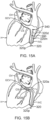
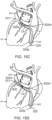
- a steerable and deflectable catheter of a catheter assembly may initially be inserted into a major vein or artery (e.g., the femoral vein) of the patient (PA) and then advanced distally along the vein or artery to position medial and distal segments of the catheter within target regions of a patient's heart with unique anatomical features.
- the medial segment may be deflected in a first direction that may also deflect the distal segment.
- the distal segment may be further advanced and deflected in a second direction. Deflection adjustments may be made to both the medial and distal segments to firmly secure catheter in place in the patient's heart, such as by frictional engagement with selected anatomical features in effectively providing a mechanical ground for the catheter relative to the heart.
- a guidewire may be advanced distally through a lumened shaft of the anchored catheter.
- the lumened shaft may be configured with a lateral opening through which a distal segment of the guidewire may be distally advanced to exit the shaft and reach additional target region of the heart with much more control than would otherwise occur in the absence of the anchored catheter.
- an apparatus in some embodiments, includes a housing body and catheter shaft, the catheter shaft including a proximal segment defining a first longitudinal axis, a medial segment defining a second longitudinal axis, and a distal segment. Also included in the apparatus is a deflection assembly configured to deflect the medial segment away from the first longitudinal axis and to deflect the distal segment away from the second longitudinal axis.
- the deflection assembly includes a first input member, a second input member, a first translating assembly and a second translating assembly.
- the first translating assembly is coupled to the medial segment, the first input member being configured to drive the first translating assembly to deflect the medial segment away from the first longitudinal axis.
- the second translating assembly is coupled to the distal segment, the second input member being configured to drive the second translating assembly to deflect the distal segment away from the second longitudinal axis.
- the first and second translating assemblies includes first and second actuator cables, respectively.
- the first and second input members are configured to drive the first and second translating assemblies, respectively, independently of each other.
- the first and second input members include first and second lever arms, respectively, configured to rotate relative to the body about a drive axis.
- the drive axis is generally perpendicular with the longitudinal axis.
- the apparatus includes an end effector extending distally from the distal segment of the catheter.
- the end effector includes at least one ablative fluid port configured to deliver an ablative fluid to targeted tissue.
- the end effector includes a pair of occluding balloons configured to transition between respective non-expanded and expanded states, and the at least one ablative fluid port is longitudinally interposed between the pair of occluding balloons.
- the end effector includes at least one electrode.
- the at least one electrode is configured to emit electrical energy.
- the at least one electrode is configured to perform electrophysiology mapping.
- the end effector includes a position sensor.
- the catheter includes an inner lumen configured to slidably receive a guidewire, and the medial segment includes an opening configured to direct the guidewire out of the inner lumen.
- the opening is configured to direct the guidewire out of the inner lumen transversely to the second longitudinal axis.
- the opening is configured to direct the guidewire out of the inner lumen parallel to the second longitudinal axis.
- the opening is formed in a sidewall of the catheter shaft.
- the opening is formed in a sidewall of the medial segment of the shaft.
- the opening includes a distal slope surface configured in a sidewall of the catheter shaft.
- the catheter shaft includes a ramp disposed in the opening.
- the ramp extends at a nonperpendicular angle relative to the longitudinal axis of the medial segment.
- the ramp includes a Y configuration.
- the ramp includes first and second divergent prongs.
- the ramp includes first and second divergent prongs and the guidewire includes a ring stop configured to engage the first and second divergent prongs.
- the guidewire includes a predetermined pre-bent configuration when the guidewire is in a neutral form.
- the guidewire includes a shape memory construction.
- the guidewire includes a distal segment, a proximal segment and a transverse segment therebetween, the distal segment and the proximal segment being parallel but not coaxial when the guidewire is in neutral form.
- an apparatus in some embodiments, includes a flexible catheter with a proximal segment defining a first longitudinal axis, a medial segment defining a second longitudinal axis, and a distal segment.
- the apparatus also includes an end effector and a deflection assembly.
- the end effector extends distally from the distal segment of the catheter and includes at least one ablative fluid port configured to deliver an ablative fluid to targeted tissue.
- the deflection assembly is configured to deflect the medial segment away from the first longitudinal axis, and to deflect the distal segment and the end effector away from the second longitudinal axis.
- the end effector includes a pair of occluding balloons configured to transition between respective non-expanded and expanded states, and the at least one ablative fluid port is longitudinally interposed between the pair of occluding balloons.
- an apparatus in some embodiments, includes a flexible catheter, a guidewire and a deflection assembly.
- the flexible catheter includes a proximal segment, a medial segment, a distal segment and an inner lumen.
- the proximal segment defines a first longitudinal axis.
- the medial segment defines a second longitudinal axis, the medial segment including an opening.
- the inner lumen extends along the proximal and medial segments to the opening.
- the guidewire slidably disposed in the inner lumen, the opening configured to direct the guidewire out of the inner lumen.
- the deflection assembly is configured to deflect the medial segment away from the first longitudinal axis, and to deflect the distal segment away from the second longitudinal axis.
- the guidewire includes at least one electrode.
- the at least one electrode is configured to perform electrophysiology mapping.
- the terms “about” or “approximately” for any numerical values or ranges indicate a suitable dimensional tolerance that allows the part or collection of components to function for its intended purpose as described herein. More specifically, “about” or “approximately” may refer to the range of values ⁇ 20% of the recited value, e.g. “about 90%” may refer to the range of values from 70% to 110%.
- the terms “patient,” “host,” “user,” and “subject” refer to any human or animal subject and are not intended to limit the systems or methods to human use, although use of the subject invention in a human patient represents a preferred embodiment.
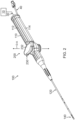
- FIG. 1 shows an exemplary medical procedure and associated components of a cardiac catheter system that may be used to provide EP mapping or cardiac ablation as referred to above.
- FIG. 1 shows a physician (PH) grasping a handle (110) of a catheter assembly (100), with an end effector (140) of a catheter (120) (shown in FIGS. 2-3 but not shown in FIG. 1 ) of catheter assembly (100) disposed in a patient (PA) to map potentials in tissue and/or ablate tissue in or near the heart (H) of the patient (PA).
- catheter assembly (100) includes handle (110), catheter (120) extending distally from handle (110), end effector (140) located at a distal end of catheter (120), and a deflection drive assembly (200) associated with handle (110).
- end effector (140) may include various components configured to deliver electrical energy to targeted tissue sites, provide EP mapping functionality, track external forces imparted on end effector (140), track the location of end effector (140), and/or disperse fluid.
- deflection drive assembly (200) is configured to deflect end effector (140) and a distal portion of catheter (120) away from a central longitudinal axis (L-L) ( FIGS. 3-5 ) defined by a proximal portion of catheter (120).
- catheter (120) includes an elongate flexible shaft (122), with end effector (140) being disposed at a distal end of shaft (122). End effector (140) and various components that are contained in shaft (122) will be described in greater detail below.
- Catheter assembly (100) is coupled with a guidance and drive system (10) via a cable (30).
- Catheter assembly (100) is also coupled with a fluid source (42) via a fluid conduit (40).
- a set of field generators (20) are positioned underneath the patient (PA) and are coupled with guidance and drive system (10) via another cable (22). Magnetic field generators (20) are merely optional.
- guidance and drive system (10) of the present example include a console (12) and a display (18).
- Console (12) includes a first driver module (14) and a second driver module (16).
- First driver module (14) is coupled with catheter assembly (100) via cable (30).
- First driver module (14) of the present example is operable to receive EP mapping signals obtained via ring-shaped electrodes (138) of end effector (140) as described in greater detail below.
- Console (12) includes a processor (not shown) that processes such EP mapping signals and thereby provides EP mapping as is known in the art.
- first driver module (14) may be further operable to provide electrical power to a distal tip member (142) of end effector (140) to thereby ablate tissue.
- Second driver module (16) is coupled with magnetic field generators (20) via cable (22). Second driver module (16) is operable to activate magnetic field generators (20) to generate an alternating magnetic field around the heart (H) of the patient (PA).
- field generators (20) may include coils that generate alternating magnetic fields in a predetermined working volume that contains the heart (H).
- First driver module (14) may also be operable to receive position indicative signals from a navigation sensor assembly (not shown) in or near end effector (140).
- the processor of console (12) is also operable to process the position indicative signals from the navigation sensor assembly to thereby determine the position of end effector (140) within the patient (PA).
- the navigation sensor assembly may include two or more coils on respective panels that are operable to generate signals that are indicative of the position and orientation of end effector (140) within the patient (PA). The coils are configured to generate electrical signals in response to the presence of an alternating electromagnetic field generated by magnetic field generators (20).
- end effector (140) may include wireless triangulation, acoustic tracking, optical tracking, inertial tracking, and the like.
- end effector (140) may lack a navigation sensor assembly.
- Display (18) is coupled with the processor of console (12) and is operable to render images of patient anatomy. Such images may be based on a set of preoperatively or intraoperatively obtained images (e.g., a CT or MRI scan, 3-D map, etc.).
- the views of patient anatomy provided through display (18) may also change dynamically based on signals from the navigation sensor assembly of end effector (140). For instance, as end effector (140) of catheter (120) moves within the patient (PA), the corresponding position data from the navigation sensor assembly may cause the processor of console (12) to update the patient anatomy views in display (18) in real time to depict the regions of patient anatomy around end effector (140) as end effector (140) moves within the patient (PA).
- the processor of console (12) may drive display (18) to show locations of aberrant conductive tissue sites, as detected via electrophysiological (EP) mapping with end effector (140) or as otherwise detected (e.g., using a dedicated EP mapping catheter, etc.).
- the processor of console (12) may drive display (18) to superimpose the locations of aberrant conductive tissue sites on the images of the patient's anatomy, such as by superimposing an illuminated dot, a crosshair, or some other form of visual indication of aberrant conductive tissue sites.
- the processor of console (12) may also drive display (18) to superimpose the current location of end effector (140) on the images of the patient's anatomy, such as by superimposing an illuminated dot, a crosshair, a graphical representation of end effector (140), or some other form of visual indication.
- Such a superimposed visual indication may also move within the images of the patient anatomy on display (18) in real time as the physician moves end effector (140) within the patient (PA), thereby providing real-time visual feedback to the operator about the position of end effector (140) within the patient (PA) as end effector (140) moves within the patient (PA).
- the images provided through display (18) may thus effectively provide a video tracking the position of end effector (140) within a patient (PA), without necessarily having any optical instrumentation (i.e., cameras) viewing end effector (140).
- display (18) may simultaneously visually indicate the locations of aberrant conductive tissue sites detected through EP mapping.
- the physician (PH) may thus view display (18) to observe the real time positioning of end effector (140) in relation to the mapped aberrant conductive tissue sites and in relation to images of the adjacent anatomical structures in the patient (PA).
- Fluid source (42) of the present example includes a bag containing saline or some other suitable fluid.
- Conduit (40) includes a flexible tube that is further coupled with a pump (44), which is operable to selectively drive fluid from fluid source (42) to catheter assembly (100). In some variations, such fluid may be expelled through openings (not shown) of distal tip member (142) of end effector (140).
- Such fluid may be provided in any suitable fashion as will be apparent to those skilled in the art in view of the teachings herein.
- end effector (140) may include various components configured to deliver electrical energy to targeted tissue sites, provide EP mapping functionality, track external forces imparted on end effector (140), track the location of end effector (140) within the patient (PA), and/or disperse fluid.
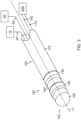
- FIG. 3 shows exemplary components of end effector (140), and other components of the distal portion of catheter (120), in greater detail.
- End effector (140) includes a distal tip member (142) secured to a distal end of shaft (122).
- a pair of actuator cables (160, 170) and a tube (180) ( FIGS. 5A-5C ) extend along the length of catheter (120) to reach end effector (140).
- Flexible shaft (122) surrounds all of the foregoing components except for distal tip member (142).
- distal tip member (142) of the present example includes a cylindraceous body (156) with a dome tip (158).
- dome tip (158) may include an electrically conductive material, such as metal.
- dome tip (158) may also be operable to apply electrical energy to tissue to thereby ablate the tissue. Such electrical energy may be communicated from first driver module (14) to distal tip member (142) via cable (30).
- Distal tip member (142) may also include one or more thermocouples that are configured to provide temperature sensing capabilities.
- a plurality of openings may be formed through cylindraceous body (156) and/or dome tip (158); and may be in communication with the hollow interior of distal tip member (142) to allow irrigation fluid to be communicated from the interior of distal tip member (142) out through cylindraceous body (156) and/or dome tip (158).
- dome tip (158) does not deliver electrical energy and/or irrigation fluid.
- distal tip member (142) of the present example also includes one or more EP mapping ring-shaped electrodes (138) mounted to cylindraceous body (156).
- cylindraceous body (156) is positioned distally in relation to electrodes (138).
- EP mapping electrodes (138) are configured to pick up electrical potentials from tissue that comes into contact with EP mapping electrodes (138).
- EP mapping electrodes (138) may thus be used to determine locations of aberrant electrical activity in tissue within a cardiovascular anatomical structure (e.g., pulmonary vein, etc.).
- Signals picked up by EP mapping electrodes (138) may be communicated through vias or other conductive structures, eventually reaching first driver module (14) of console (12) via cable (30).
- First driver module (14) may process the EP mapping signals and provide the physician (PH) with corresponding feedback indicating the locations of aberrant electrical activity in accordance with the teachings of various references cited herein.
- an electrically insulating material may be interposed between cylindraceous body (156) and EP mapping electrodes (138) to thereby electrically isolate EP mapping electrodes (138) from cylindraceous body (156).
- EP mapping electrodes (138) may be constructed and operable in accordance with the teachings of various patent references cited herein. While two EP mapping electrodes (138) are shown, distal tip member (142) may include one or more than two EP mapping electrodes (138). Alternatively, distal tip member (142) may lack EP mapping electrodes (138) altogether.
- catheter assembly (100) includes a deflection drive assembly (200) configured to deflect end effector (140) away from the central longitudinal axis (L-L) defined by a proximal portion of catheter (120).
- Deflection drive assembly (200) of the present example incudes actuator cables (160, 170), a cable driver assembly (not shown), a rocker arm (230), and a load limiter assembly (not shown).
- the physician (PA) may actuate rocker arm (230) relative to handle (110) such that the cable driver assembly actuates actuator cables (160, 170) in a simultaneous, longitudinally-opposing motion to selectively deflect end effector (140) laterally away from a longitudinal axis (L-L), thereby enabling the physician (PH) to actively steer end effector (140) within the patient (PA).
- Handle (110) includes a first casing portion (112) and a second casing portion (114) together defining an internal cavity (not shown).
- Actuator cables (160, 170) include respective intermediary portions (162, 172), distal portions (not shown), and proximal end blocks (not shown).
- the proximal end blocks serve as a mechanical ground for actuator cables (160, 170).
- the distal end portions are coupled with end effector (140) to prevent actuator cables (160, 170) from being pulled proximally out of end effector (140).
- Intermediary portions (162, 172) extend proximally from the distal portions, through elongate flexible shaft (122) of catheter (120) (as best shown in FIGS. 5A-5C ), into the cable driver assembly, and terminate into proximal end blocks. Intermediary portions (162, 172) each wrap around a portion of the cable driver assembly such that movement of the cable driver assembly relative to handle (110) may actuate actuator cables (160, 170) simultaneously in opposite directions.
- the cable driver assembly is rotationally coupled with handle (110).
- cable driver (210) is configured to rotate about a drive axis such that suitable rotation of rocker arm (230) relative to handle (110) may drive rotation of cable driver (210) about a drive axis (D-A).
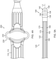
- FIGS. 4A-5C show exemplary use of deflection drive assembly (200) to deflect end effector (140) and the distal portion of catheter (120) about central longitudinal axis (L-L).
- FIGS. 4A and 5A show various sections of catheter assembly (100) when end effector (140) is in a neutral, non-deflected position.
- FIG. 4A shows rocker arm (230) in a neutral rotational position relative to handle (110). When rocker arm (230) is in the first rotational position, the cable driver assembly is in a corresponding first rotation position such that actuator cables (160, 170) are in a first longitudinal position associated with end effector (140) being in the non-deflected position as shown in FIG. 5A .
- the physician (PH) may rotate rocker arm (230) relative to handle (110) to the position shown in FIG. 4B .
- Rotation of rocker arm (230) to the rotational position shown in FIG. 4B drives the cable driver assembly into a corresponding rotational position such that actuator cable (170) is driven proximally and actuator cable (160) actuates distally, to thereby drive end effector (140) to bend to the position shown in FIG. 5B .
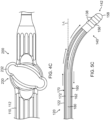
- the physician (PH) may rotate rocker arm (230) relative to handle (110) to the position shown in FIG. 4C .
- Rotation of rocker arm (230) to the rotational position shown in FIG. 4C drives the cable driver assembly into a corresponding rotational position such that actuator cable (160) is driven proximally and actuator cable (170) actuates distally, to thereby drive end effector (140) to bend to the position shown in FIG. 5C .
- catheter assembly (100) may be configured and operable in accordance with one or more teachings of U.S. Pub. No. 2020/0405182, entitled “Catheter Deflection System with Deflection Load Limiter,” published December 31, 2020 , the disclosure of which is incorporated by reference herein.
- catheter (120) it may be desirable to securely stabilize a portion of catheter (120) in a substantially fixed position within the heart (H) to inhibit inadvertent movement (e.g., slipping) of catheter (120) that might otherwise result from patient cardioversion or inadvertent movement of handle (110) by the physician (PH), such as during EP mapping and/or tissue ablation.
- PH inadvertent movement
- catheter (120) itself
- an ablative fluid such as ethanol (alcohol).
- FIGS. 6-13E show an example of a catheter assembly (300) that may function in such a manner and that may be incorporated into the cardiac ablation catheter system of FIG. 1 in place of catheter assembly (100).
- Catheter assembly (300) may be configured and operable like catheter assembly (100) described above except as otherwise described below.
- catheter assembly (300) includes a handle (310), a catheter (320) extending distally from handle (310), an end effector (340) located at a distal end of catheter (320), and a deflection drive assembly (400) associated with handle (310).
- catheter assembly (300) also includes a guidewire (500) ( FIGS.
- Handle (310) may include any suitable actuation features for driving translation of guidewire (500) relative to catheter (320), including but not limited to a slider, a pivoting rocker, a dial, etc.
- end effector (340) includes various components configured to provide EP mapping functionality and/or deliver ablative fluid to targeted tissue sites.
- end effector (340) may additionally or alternatively include various components configured to deliver electrical energy to targeted tissue sites, track external forces imparted on end effector (340), track the location of end effector (340), and/or disperse irrigation fluid.
- end effector (340) may be configured and operable in accordance with one or more teachings of U.S. Pub. No. 2020/0405182, entitled “Catheter Deflection System with Deflection Load Limiter," published December 31, 2020 , the disclosure of which is incorporated by reference herein.
- end effector (340) includes one or more features that are operable to deliver electrical energy to tissue (e.g., to ablate the tissue)
- electrical energy delivery features may be provided in addition to, or in lieu of, ablative fluid delivery features as described below.
- some variations of end effector (340) may omit electrical energy delivery features and ablative fluid delivery features, such that neither type of feature is necessarily essential.
- deflection drive assembly (400) is configured to deflect a medial segment (320m) of catheter (320) away from a first central longitudinal axis (L1) defined by a proximal segment (320p) of catheter (320); and to deflect end effector (340) and a distal segment (320d) of catheter (320) away from a second central longitudinal axis (L2) defined by medial segment (320m) of catheter (320).
- guidewire (500) is configured to provide EP mapping functionality in regions of the heart (H) that may not be readily accessible by end effector (140); and to assume a configuration in which a distal segment (500d) of guidewire (500) is deflected away from a third central longitudinal axis (L3) defined by a proximal segment (500p) of guidewire (500).
- catheter (320) includes an elongate flexible shaft (322), with end effector (340) being disposed at a distal end (324) of shaft (322). End effector (340) and various components that are contained in/on shaft (322) will be described in greater detail below.
- Catheter assembly (300) is coupled with guidance and drive system (10) via cable (30).
- Catheter assembly (300) is also coupled with fluid source (42) via fluid conduit (40).
- fluid source (42) includes a bag containing ethanol (alcohol) or some other suitable ablative fluid.
- fluid source (42) may instead take any other suitable form and contain any other suitable fluid.
- end effector (340) includes various components configured to provide EP mapping functionality and/or deliver ablative fluid to targeted tissue sites.
- end effector (340) includes a distal tip member (342) secured to distal end (324) of shaft (322).
- a first actuator cable (360) and a tube (not shown) or other structure defining a lumen extend along the length of catheter (320) to reach end effector (340).
- Flexible shaft (322) surrounds all of the foregoing components except for distal tip member (342).
- distal tip member (342) of the present example includes a cylindraceous body (356) having a distal tip (357).
- Distal tip (357) is atraumatic and may have either a flat or dome shape, for example. In some other versions, distal tip (357) may have any other suitable atraumatic configuration.
- Distal tip member (342) is fixedly secured to shaft (322) at or near distal end (324) of shaft (322).
- cylindraceous body (356) may include a proximal socket (not shown) that receives distal end (324) of shaft (322) and is fixedly secured to shaft (322).
- distal tip member (342) may be welded to shaft (322), soldered to shaft (322), adhered to shaft (322) using an adhesive or epoxy, press-fit onto shaft (322), and/or fixedly secured to shaft (322) in any other suitable fashion.
- cylindraceous body (356) may be integrally formed together with a cylindrical sidewall of shaft (322) as a unitary (e.g., monolithic) piece.
- a plurality of ablative fluid delivery ports (358) extend radially through cylindraceous body (356) and are in fluid communication with fluid conduit (40) via the tube extending along the length of catheter (320). Ports (358) thus allow ablative fluid to be communicated from fluid source (42) out through cylindraceous body (356).
- fluid delivery ports (358) may be in fluid communication with a source of suction (not shown). In some versions, some ports (358) may be in fluid communication with one of fluid conduit (40) or the source of suction, while other ports (358) may be in fluid communication with the other of fluid conduit (40) or the source of suction.
- distal tip member (342) may include any suitable number of fluid delivery ports (358).
- a large quantity of minute fluid delivery ports (358) may be defined by one or more porous portions of cylindraceous body (356).
- distal tip member (142) may lack fluid delivery ports (358) altogether.
- distal tip member (342) of the present example also includes proximal and distal occluding balloons (380, 382) mounted to cylindraceous body (356), such that each of the ablative fluid delivery ports (358) is longitudinally interposed between occluding balloons (380, 382).
- Occluding balloons (380, 382) are each in fluid communication with an inflation fluid source (not shown), which may include a bag containing saline or some other suitable inflation fluid, via one or more inflation fluid conduits (not shown).
- the inflation fluid may thus be communicated from the inflation fluid source to each occluding balloon (380, 382) to transition occluding balloons (380, 382) from respective non-expanded states ( FIG. 7A ) to respective expanded states ( FIG. 7B ); and back from each occluding balloon (380, 382) to the inflation fluid source to transition occluding balloons (380, 382) from the respective expanded states ( FIG. 7B ) to the respective non-expanded states ( FIG. 7A ).
- occluding balloons (380, 382) may be in fluid communication with the inflation fluid source via a single shared inflation fluid conduit, such that occluding balloons (380, 382) may be configured to transition between the respective expanded and non-expanded states substantially simultaneously with each other.
- occluding balloons (380, 382) may be in fluid communication with the inflation fluid source via two separate inflation fluid conduits, such that occluding balloons (380, 382) may be configured to transition between the respective expanded and non-expanded states independently of each other.
- distal tip member (142) may lack occluding balloons (380, 382) altogether.
- occluding balloons (380, 382) When in the respective expanded states, occluding balloons (380, 382) may be configured to sealingly engage corresponding portions of an inner surface of an anatomical structure, such as a lumen.
- occluding balloons (380, 382) may be configured to sealingly engage corresponding portions of an inner surface of a blood vessel at or near the heart (H) (e.g., the oblique vein of the left atrium) when in the respective expanded states.
- H heart
- occluding balloons (380, 382) may be configured to cooperate with each other when in the respective expanded states to fluidly isolate the region of the blood vessel that extends longitudinally between occluding balloons (380, 382), in which ablative fluid delivery ports (358) are located, from other regions of the blood vessel, to thereby inhibit ablative fluid from inadvertently contacting non-targeted tissue outside of the fluidly isolated region of the blood vessel. Occluding balloons (380, 382) may thus promote controlled delivery of ablative fluid into the fluidly isolated region of the blood vessel.
- distal tip member (342) of the present example also includes one or more EP mapping ring-shaped electrodes (338) mounted to cylindraceous body (356).
- EP mapping electrodes (338) are configured to pick up electrical potentials from tissue that comes into contact with EP mapping electrodes (338).
- EP mapping electrodes (338) may thus be used to determine locations of aberrant electrical activity in tissue within a cardiovascular anatomical structure (e.g., pulmonary vein, etc.).
- Signals picked up by EP mapping electrodes (338) may be communicated through vias or other conductive structures, eventually reaching first driver module (14) of console (12) via cable (30).
- First driver module (14) may process the EP mapping signals and provide the physician (PH) with corresponding feedback indicating the locations of aberrant electrical activity in accordance with the teachings of various references cited herein.
- EP mapping electrodes (338) may be constructed and operable in accordance with the teachings of various patent references cited herein. While two EP mapping electrodes (338) are shown, distal tip member (342) may include one or more than two EP mapping electrodes (338). Alternatively, distal tip member (342) may lack EP mapping electrodes (338) altogether.
- distal tip member (342) may be configured to deliver electrical energy to target tissue.
- electrical energy may include radiofrequency (AC type) electrical energy, pulsed field (DC type) electrical energy (e.g., irreversible electroporation, etc.), or some other form of electrical energy.
- cylindraceous body (356) may be formed of an electrically conductive material, such as metal.
- distal tip member (342) may include one or more electrically conductive elements secured to cylindraceous body (356).
- catheter (320) includes at least one navigation sensor assembly (not shown), fixedly secured relative to shaft (322) and/or cylindraceous body (356), that is operable to generate signals (e.g., in response to the presence of an alternating electromagnetic field generated by field generators (20)) that are indicative of the position and orientation of shaft (322) and/or distal tip member (342) within the patient (PA), such as in a manner similar to that described above.
- navigation sensor assembly (not shown), fixedly secured relative to shaft (322) and/or cylindraceous body (356), that is operable to generate signals (e.g., in response to the presence of an alternating electromagnetic field generated by field generators (20)) that are indicative of the position and orientation of shaft (322) and/or distal tip member (342) within the patient (PA), such as in a manner similar to that described above.
- Such a navigation sensor assembly may be configured as a single-axis sensor (SAS) (e.g., having a single electromagnetic coil wound about a single axis), as a dual-axis sensor (DAS) (e.g., having two electromagnetic coils wound about respective axes), or as a triple-axis sensor (TAS) (e.g., having three electromagnetic coils wound about respective axes).
- SAS single-axis sensor
- DAS dual-axis sensor
- TAS triple-axis sensor
- such a navigation sensor assembly may be configured as a flexible printed circuit board (PCB).
- PCB flexible printed circuit board
- such a navigation sensor assembly may be configured and operable in accordance with at least some of the teachings of U.S. Pub. No. 2022/0257093, entitled “Flexible Sensor Assembly for ENT Instrument,” published August 18, 2022 , the disclosure of which is incorporated by reference herein, in its entirety.
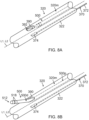
- catheter (320) includes a lateral opening (also referred to as a lateral aperture) (390) extending radially through the cylindrical sidewall of shaft (322) at or near a distal end of medial segment (320m) of catheter (320). Lateral opening (390) is thus proximal to end effector (340). Lateral opening (390) may define a distal end of an inner lumen (392) of shaft (322) in which guidewire (500) is slidably received, such that lateral opening (390) may be configured to direct guidewire (500) from inner lumen (392) of shaft (322) to an exterior of shaft (322).
- a lateral opening also referred to as a lateral aperture
- lateral opening (390) provides a pathway for guidewire (500) that is distally advanced through inner lumen (392) of shaft (322) to protrude laterally from the distal end of medial segment (320m) of catheter (320) or otherwise be exposed relative to the distal end of medial segment (320m).
- lateral opening (390) may facilitate side-exiting of guidewire (500) out of inner lumen (392) of catheter (320) in a direction transverse to the longitudinal axis (L2) defined by medial segment (320m), such that guidewire (500) may be extended and retracted relative to lateral opening (390) to transition guidewire (500) between a retracted position ( FIG. 8A ) and at least one extended position ( FIG.
- a second actuator cable (370) extends along the length of proximal and medial segments (320p, 320m) of catheter (320) to reach the distal end of medial segment (320m) at or near lateral opening (390), as described in greater detail below.
- medial and distal segments (320m, 320d) of catheter (320) have a same cross-dimension (e.g., diameter) as each other.
- distal segment (320d) may have a smaller cross-dimension than that of medial segment (320m).
- the cylindrical sidewall of shaft (322) may define a generally annular distally-facing surface at the distal end of medial segment (320m); and opening (390) may extend through the annular surface. In this manner, opening (390) may facilitate exiting of guidewire (500) out of inner lumen (392) of catheter (320) in a direction parallel to the longitudinal axis (L2) defined by medial segment (320m).
- guidewire (500) of this example includes an elongate member (502) extending to a distal end (504).
- Elongate member (502) may include a shaft or a coil, for example.
- the coil may be wrapped about a core wire (not shown), which may be secured relative to distal end (504) and prevent the coil from elongating when the coil is placed under tensile stress.
- Elongate member (502) is sized for insertion through inner lumen (392) of catheter (320). Catheter (320) may thus be used to assist in positioning a tip member (512) of guidewire (500) in relation to a target region of the heart (H).
- guidewire (500) may include a locking member (not shown) configured to selectively affix guidewire (500) relative to catheter (320), such as to maintain a select portion of guidewire (500) extended relative to lateral opening (390) when guidewire (500) is in the at least one extended position ( FIG. 8B ).
- distal segment (500d) of guidewire (500) is flexible, such that guidewire (500) may transition between a straight configuration ( FIG. 8A ) in which distal segment (500d) is coaxial with a proximal segment (500p) of guidewire (500), and a bent and/or curved configuration ( FIGS. 8B and 9 ) in which distal segment (500d) and guidewire tip member (512) are deflected away from a third central longitudinal axis (L3) defined by proximal segment (500p).
- third longitudinal axis (L3) may be parallel to or colinear with second longitudinal axis (L2).
- distal segment (500d) is pre-bent and/or pre-curved.
- distal segment (500d) may be pre-formed to define a bend and/or curve; or may otherwise be predisposed to define the bend and/or curve in the absence of external forces acting upon guidewire (500), such that guidewire (500) may be resiliently biased to assume the bent and/or curved configuration. As shown in FIGS.
- guidewire (500) may be configured to be restrained by inner lumen (392) of catheter (320) to assume the straight configuration while distal segment (500d) is slidably received within inner lumen (392) of catheter (320) (e.g., when guidewire (500) is in the retracted position), and to resiliently assume the bent and/or curved configuration in response to distal segment (500d) exiting inner lumen (392) of catheter (320) (e.g., when guidewire (500) is in the at least one extended position).
- inner lumen (392) may include a ramp and/or other structural feature that assists in urging distal segment (500d) laterally away from longitudinal axis (L2) as distal segment (500d) exits catheter (320) via lateral opening (390).
- distal segment (500d) of guidewire (500) may be configured to promote advancement of guidewire (500) along a curved pathway defined by an anatomical structure, such as a lumen.
- distal segment (500d) may be configured to promote advancement of guidewire (500) along a curved pathway defined by one or more blood vessels at or near the heart (H) (e.g., the coronary sinus and/or great cardiac vein) when in the bent and/or curved configuration.
- H blood vessels at or near the heart
- distal segment (500d) may be configured to reduce the risk of distal tip member (512) puncturing or otherwise imparting undesired trauma to such blood vessel(s) when in the bent and/or curved configuration.
- distal segment (500d) may be predisposed to be straight relative to proximal segment (500p), such as in cases in which opening (390) is configured to facilitate exiting of guidewire (500) out of inner lumen (392) of catheter (320) in a direction parallel to the longitudinal axis (L2) defined by medial segment (320m).
- inner lumen (392) may include a ramp and/or other structural feature that assists in urging distal segment (500d) laterally away from longitudinal axis (L2) as distal segment (500d) exits catheter (320) via lateral opening (390), and distal segment (500d) may simply extend straight along that path as urged by the ramp and/or other structural feature of inner lumen.
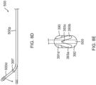
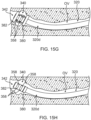
- the lateral opening (390) configured in the sidewall of the catheter shaft (322) is defined by at least sloped portions of the surface that surrounds the lateral opening, including proximal slope surface (391d) and distal slope surface (391d) that form angles that are, respectively, lesser than and greater than 90 degrees with outer surface (395) of the shaft.
- the sloped surfaces, especially, the distal sloped surface (391d) facilitate the distal segment (500d) of the guidewire (500) to exit the lumen (392) of the shaft (322).
- a ramp (393) extends generally from the distal sloped surface (391d) into the lumen (392).
- the ramp (393) is sloped and assumes a similar angle as that of the distal sloped surface (391d) such that the guidewire (500), whether or not having a straight configuration or having a pre-bent and/or pre-curved configuration, can rest against and be guided by the ramp in exiting the lumen (392).
- the ramp may be shaped as a spade or a shovel. As shown in FIG.
- the guidewire may have shape-memory characteristics such that it has a pre-bent or pre-curved configuration wherein distal segment 500d extends at an angle relative to proximal segment 500p when the guidewire is in a neutral form (see solid lines) and can be resiliently straightened when exposed to external forces or constraints (see broken lines), for example, when passing through a lumen.
- the ramp (393) is "Y" shaped with two diverging prongs (393a, 393b) and a notch (393c) therebetween sized and shaped to support and can help stabilize the guidewire (500) in the lateral opening (390).
- the guidewire (500) may include a ring stop 397 (see FIG. 8D ) that is configured to abut the prongs (393a, 393b) of the ramp in generally affixing guidewire (500) relative to catheter (320), such as to maintain a portion of guidewire (500) extended relative to lateral opening (390).
- the length of the ramp (393) or its prongs (393a, 393b) may depend on or be relative to the inner diameter of the lumen (392) such that the length may range between about 20% to about 60% of the inner diameter, so that the ramp is configured to better "catch" the distal end of the guidewire as it advances distally toward the lateral opening (390) and help direct and feed the distal segment (500d) toward the lateral opening (390).
- the distal segment (500d) as it is further advanced distally and exits the lateral opening (390) defines a third central longitudinal axis (L3) that extends at an angle relative to the second central longitudinal axis (L2) defined by the medial segment (320m) of the shaft (322).
- the distal segment (500d) and the third central longitudinal axis (L3) defined thereby may continue to extend along the angle relative to the second longitudinal axis (L2) or they extend parallel with the second longitudinal axis (L2).
- a guidewire may have shape-memory characteristics and be configured with a pre-bent or pre-curved configuration, such as "kink," where the distal segment 500d and the proximal segment 500p are connected by an off-angle transverse segment 500t.
- the segments 500d and 500p are parallel but not coaxial when the guidewire is in its neutral form (see solid lines) and can be resiliently straightened when subjected to external forces or constraints (see broken lines), for example, when passing through a lumen.
- the guidewire can therefore resiliently assume a straight configuration when being advanced distally through the lumen (392) and bend and flex as needed when the distal segment (500d) encounters the ramp (393).
- the ramp guides the distal segment (500d) through the lateral opening (390).
- the distal segment (500d) and the third central longitudinal axis (L3) extend generally parallel with the second central longitudinal axis (L2).
- the location of the transverse segment 500t may be at any suitable location along the length of the guidewire. In instances where the transverse segment 500t is to remain in the lateral opening (390), the distal segment (500d) is of a sufficient length such that the distal end of the guidewire can reach the target tissue site.
- guidewire tip member (512) of the present example includes a cylindraceous body (516) having a distal tip (517).
- Distal tip (517) of the present example has a dome shape, such that distal tip (517) is atraumatic. In some other versions, distal tip (517) may have any other suitable atraumatic configuration.
- Guidewire tip member (512) is fixedly secured to elongate member (502) at or near distal end (504) of elongate member (502).
- cylindraceous body (516) may include a proximal socket (not shown) that receives distal end (504) of elongate member (502) and is fixedly secured to elongate member (502).
- guidewire tip member (512) may be welded to elongate member (502), soldered to elongate member (502), adhered to elongate member (502) using an adhesive or epoxy, press-fit onto elongate member (502), and/or fixedly secured to elongate member (502) in any other suitable fashion.
- guidewire tip member (512) of the present example also includes one or more EP mapping ring-shaped electrodes (518) mounted to body (516).
- EP mapping electrodes (518) are configured to pick up electrical potentials from tissue that comes into contact with EP mapping electrodes (518).
- EP mapping electrodes (518) may thus be used to determine locations of aberrant electrical activity in tissue within a cardiovascular anatomical structure (e.g., pulmonary vein, etc.).
- Signals picked up by EP mapping electrodes (518) may be communicated through vias or other conductive structures, eventually reaching first driver module (14) of console (12) via cable (30).
- First driver module (14) may process the EP mapping signals and provide the physician (PH) with corresponding feedback indicating the locations of aberrant electrical activity in accordance with the teachings of various references cited herein.
- EP mapping electrodes (518) may be constructed and operable in accordance with the teachings of various patent references cited herein. While two EP mapping electrodes (518) are shown, guidewire tip member (512) may include one or more than two EP mapping electrodes (518). Alternatively, guidewire tip member (512) may lack EP mapping electrodes (518) altogether.
- guidewire tip member (512) may be configured to deliver electrical energy to target tissue.
- electrical energy may include radiofrequency (AC type) electrical energy, pulsed field (DC type) electrical energy (e.g., irreversible electroporation, etc.), or some other form of electrical energy.
- cylindraceous body (516) may be formed of an electrically conductive material, such as metal.
- guidewire tip member (512) may include one or more electrically conductive elements secured to cylindraceous body (516).
- guidewire (500) may be configured and operable in accordance with at least some of the teachings of U.S. Pat. No. 11,213,344, entitled “Guidewire with Ablation and Coagulation Functionality,” issued January 4, 2022 , the disclosure of which is incorporated by reference herein, in its entirety; U.S. Pat. No. 10,603,472, entitled “Guidewires Having Improved Mechanical Strength and Electromagnetic Shielding,” issued March 31, 2020 , the disclosure of which is incorporated by reference herein, in its entirety; and/or U.S. Pub. No. 2021/0196370, entitled “Neurosurgery Guidewire with Integral Connector for Sensing and Applying Therapeutic Electrical Energy,” published July 1, 2021 , the disclosure of which is incorporated by reference herein, in its entirety.
- guidewire (500) includes at least one navigation sensor assembly (not shown) fixedly secured to elongate member (502) that is operable to generate signals (e.g., in response to the presence of an alternating electromagnetic field generated by field generators (20)) that are indicative of the position and orientation of elongate member (502) and/or tip member (512) within the patient (PA), such as in a manner similar to that described above.
- navigation sensor assembly fixedly secured to elongate member (502) that is operable to generate signals (e.g., in response to the presence of an alternating electromagnetic field generated by field generators (20)) that are indicative of the position and orientation of elongate member (502) and/or tip member (512) within the patient (PA), such as in a manner similar to that described above.
- Such a navigation sensor assembly may be configured as a single-axis sensor (SAS) (e.g., having a single electromagnetic coil wound about a single axis), as a dual-axis sensor (DAS) (e.g., having two electromagnetic coils wound about respective axes), or as a triple-axis sensor (TAS) (e.g., having three electromagnetic coils wound about respective axes).
- SAS single-axis sensor
- DAS dual-axis sensor
- TAS triple-axis sensor
- such a navigation sensor assembly may be configured as a flexible printed circuit board (PCB).
- PCB flexible printed circuit board
- such a navigation sensor assembly may be configured and operable in accordance with at least some of the teachings of U.S. Pub. No. 2022/0257093, entitled “Flexible Sensor Assembly for ENT Instrument,” published August 18, 2022 , the disclosure of which is incorporated by reference herein, in its entirety.
- guidewire (500) has been described as being slidably received within inner lumen (392) of catheter (320) for accessing and providing EP mapping functionality to regions of the heart (H) that may not be readily accessed by catheter (320) itself, it will be appreciated that any other suitable type of device may be slidably received within inner lumen (392) of catheter (320) for any other suitable purposes.
- a second catheter (not shown) may be incorporated into catheter assembly (300) in place of guidewire (500).
- Such a second catheter may include any one or more of the features described above with respect to guidewire (500).
- catheter assembly (300) includes a deflection drive assembly (400) configured to deflect medial segment (320m) of catheter (320) away from first central longitudinal axis (L1) defined by proximal segment (320p) of catheter (320); and to deflect end effector (340) and distal segment (320d) of catheter (320) away from second central longitudinal axis (L2) defined by medial segment (320m) of catheter (320).
- first and second longitudinal axes (L1, L2) may be colinear with each other when medial segment (320m) is not deflected away from first longitudinal axis (L1).
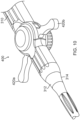
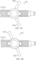
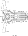
- Deflection drive assembly (400) of the present example includes actuator cables (360, 370) and a cable driver assembly (410) including a pair of lever arms (420a, 420b).
- the physician (PA) may actuate lever arms (420a, 420b) relative to handle (310) independently of each other such that cable driver assembly (410) actuates the corresponding actuator cables (360, 370) to selectively deflect medial segment (320m) away from first central longitudinal axis (L1), and/or to selectively deflect end effector (340) and distal segment (320d) away from second central longitudinal axis (L2), thereby enabling the physician (PH) to actively steer end effector (340) within the patient (PA) and/or to securely anchor a distal portion of catheter (320) relative to one or more anatomical structures of the patient (PA).
- Handle (310) includes a housing body with a first casing portion (312) and a second casing portion (314) together defining an internal cavity (302).
- First casing portion (312) defines a through hole (not shown) dimensioned to rotatably house a central body (412) of cable driver assembly (410).
- Lever arms (420a, 420b) may each suitably couple with central body (412) in accordance with description herein.
- first casing portion (312) may include a pair of stops (not shown) located on opposite sides of the through hole and configured to limit the rotation of lever arms (420a, 420b) relative to handle (310).
- an interior of second casing portion (314) includes a partition wall (304) and a pair of tension adjustment channels (308) located on opposite lateral sides of partition wall (304).
- Partition wall (304) and respective tension adjustment channels (308) together define a sliding channel (306).
- Each sliding channel (306) slidably houses a respective sliding body (365, 375).
- Sliding bodies (365, 375) are attached to respective actuator cables (360, 370).
- Sliding bodies (365, 375) and sliding channels (306) may together assist in guiding the translation of portions of actuator cables (360, 370) extending distally from sliding bodies (365, 375) in accordance with the description herein.
- Tension adjustment channels (308) include a linear array of laterally extending, rectangular projections. Tension adjustment channels (308) are configured to receive respective tension blocks (368, 378), which also each have a complementary linear array of laterally extending rectangular projections. The complementary rectangular projections of tensions blocks (368, 378) and tension adjustment channels (308) are configured to longitudinally fix tension blocks (368, 378) relative to second casing portion (314). In other words, tension adjustment channels (308) are configured to receive tension blocks (368, 378) in a tongue-and-groove fashion to fix tension blocks (368, 378) relative to handle (310). Tension blocks (368, 378) may be selectively inserted along various suitable locations within adjustment channels (308) in order to serve as a mechanical ground for actuator cables (360, 370).
- Tension blocks (368, 378) may be inserted along various locations within adjustment channels (308) in order to adjust the tension within actuator cables (360, 370) to thereby accommodate for length variations of actuator cables (360, 370) due to various factors, such as manufacturing tolerance variations, deformation of actuator cables (360, 370), etc.
- Actuator cables (360, 370) include respective intermediary portions (362, 372), distal portions (364, 374) (as best seen in FIGS. 7A-8B ), and proximal end blocks (366, 376) (as best seen in FIGS. 12A-12C .
- proximal end blocks (366, 376) are housed within tension adjustment channels (308) just distal to tension blocks (368, 378).
- Tension blocks (368, 378) therefore prevent proximal end blocks (366, 376) from actuating proximally within adjustment channels (308), thereby serving as a mechanical ground for actuator cables (360, 370).
- Proximal end blocks (366, 376) are fixed to respective intermediary portions (362, 372).
- Tension blocks (368, 378) define a through hole that intermediary portions (362, 372) extend through such that intermediary portions (362, 372) may extend from proximal end blocks (366, 376) through adjustment channels (308) in order to suitably couple with cable driver assembly (410).
- tension blocks (368, 378) and respective proximal end blocks (366, 376) may be formed of a single piece.
- respective distal portions (364, 374) have a larger outer cross dimension (e.g., width, thickness, diameter, etc.) than the outer diameter of respective intermediary portions (362, 372).
- First distal end portion (364) is coupled with end effector (340) to prevent actuator cable (360) from being pulled proximally out of end effector (340), while second distal end portion (374) is coupled with the distal end of medial segment (320m) of catheter (320) to prevent actuator cable (370) from being pulled proximally out of medial segment (320m).
- Suitable ways in which actuator cables (360, 370) may be coupled with (or anchored in or near) end effector (340) and medial segment (320m), respectively, will be apparent to those skilled in the art in view of the teachings herein.
- the catheter With the distal end portion (364, 374) of each actuator cable (360, 370) anchored in the catheter (320) at a different location along the length of the catheter (320), the catheter advantageously exhibits a different respective deflection curve along the side of the catheter along which the respective actuator cable extends. As the respective deflection curve ends at the location of the respective anchor location, different respective anchor locations on different/opposing sides of the catheter provides asymmetric deflections, as needed or desired.
- Intermediary portions (362, 372) extend proximally from distal portions (364, 374), through elongate flexible shaft (322) of catheter (320) (as best shown in FIGS. 7A-8B ), into cable driver assembly (410), and terminate into proximal end blocks (366, 376) (as best shown in FIGS. 12A-12C ).
- Intermediary portions (362, 372) may include various segments coupled to each other in order to extend between distal portions (364, 374) and proximal end blocks (366, 376).
- Various segments of intermediary portions (362, 372) may be coupled through any suitable means as would be apparent to one skilled in the art in view of the teachings herein.
- Intermediary portions (362, 372) each wrap around a corresponding portion of cable driver assembly (410) such that movement of the corresponding lever arm (420a, 420b) relative to handle (310) may actuate the respective actuator cable (360, 370).
- cable driver assembly (410) includes central body (412), with lever arms (420a, 420b) extending laterally from central body (412).
- Central body (412) is fixedly coupled with handle (310) while lever arms (420a, 420b) of cable driver assembly (410) are each rotationally coupled with handle (110) via central body (412).
- lever arms (420a, 420b) are each configured to rotate about a drive axis (D-A) independently of each other.
- central body (412) may define a pair of lateral slots (not shown) configured to receive respective portions of lever arms (420a, 420b).
- Lever arms (420a, 420b) of cable driver assembly (410) are configured to couple with a respective actuator cable (360, 370) such that rotation of each lever arm (420a, 420b) about drive axis (D-A) actuates the corresponding actuator cable (360, 370) in accordance with the description herein.
- Each lever arm (420a, 420b) defines a cable recess (422) and a plug opening (424) extending into cable recess (422).
- Each cable recess (422) is dimensioned to receive the intermediary portions (362, 372) of the corresponding actuator cable (360, 370), while each plug opening (424) is dimensioned to receive a corresponding cable plug (426) such that each cable plug (426) actuates with the respective lever arm (420a, 420b).
- Each cable recess (422) is dimensioned to accommodate the corresponding cable plug (426) such that intermediary portions (362, 372) may each wrap around the corresponding cable plug (426), thereby suitably coupling intermediary portion (362, 372) of actuator cables (360, 370) with cable driver assembly (410).
- Cable plugs (426) each interact with the respective intermediary portion (362, 372) such that proximal movement of a cable plug (426) pulls the respective intermediary portion (362, 372) proximally.
- FIGS. 11A-13C show exemplary use of deflection drive assembly (400) to deflect medial segment (320m) of catheter (320) away from first central longitudinal axis (L1) defined by proximal segment (320p) of catheter (320), and to deflect end effector (340) and distal segment (320d) of catheter (320) away from second central longitudinal axis (L2) defined by medial segment (320m) of catheter (320).
- FIGS. 11A , 12A , and 13A show various sections of catheter assembly (300) when end effector (340) is in a neutral, non-deflected position.
- FIG. 11A shows both lever arms (420a, 420b) in a neutral rotational position relative to handle (110). As best shown in FIG.
- the physician (PH) may rotate second lever arm (420b) relative to handle (310) to the position shown in FIG. 11B .
- rotation of second lever arm (420b) to the rotational position shown in FIG. 11B actuates plug (426) associated with actuator cable (370) to drive actuator cable (370) proximally.
- Plug (426) associated with actuator cable (360) may remain unactuated.
- Proximal translation of actuator cable (370) drives sliding body (375) proximally within the respective sliding channel (306), while sliding body (365) may remain substantially stationary within sliding channel (306) relative to its position in FIG. 12A .
- Proximal translation of sliding body (375) drives the section of intermediate portion (372) extending distally from sliding body (375), as well as distal portion (374), proximally. Since distal portion (374) may not actuate proximally out of the distal end of medial segment (320m), as described above, proximal translation of distal portion (374) drives medial segment (320m) to bend to the position shown in FIG. 13B . It will be appreciated that such deflection of medial segment (320m) may result in deflection of end effector (340) and distal segment (320d) in the first direction.
- first lever arm (420a) may rotate first lever arm (420a) relative to handle (310) to the position shown in FIG. 11C .
- rotation of first lever arm (420a) to the rotational position shown in FIG. 11C actuates plug (426) associated with actuator cable (360) to drive actuator cable (360) proximally.
- Plug (426) associated with actuator cable (370) may remain actuated.
- Proximal translation of actuator cable (360) drives sliding body (365) proximally within sliding channel (306), while sliding body (375) may remain substantially stationary within sliding channel (106) relative to its position in FIG. 12B .
- Proximal translation of sliding body (365) drives the section of intermediate portion (362) extending distally from sliding body (365), as well as distal portion (364), proximally. Since distal portion (364) may not actuate proximally out of end effector (340), as described above, proximal translation of distal portion (364) drives end effector (340) together with distal segment (320d) to bend to the position shown in FIG. 13C .
- medial segment (320m) is deflected away from first central longitudinal axis (L1) on a first side of catheter (320) in a first plane and distal segment (320d) is deflected away from second central longitudinal axis (L2) on a second side of catheter (320) in the first plane such that catheter (320) may exhibit asymmetric deflections, for example, a serpentine shape, such as an "S" shape, in the first plane.
- a serpentine shape such as an "S" shape
- medial segment (320m) and distal segment (320d) of catheter (320) are both deflected may vary from the "S" shape shown in FIG. 13C .
- medial and distal segments (320m, 320d) are each deflected at generally right angles relative to the respective longitudinal axes (L1, L2).
- medial and distal segments (320m, 320d) may each be only partially deflected, so that medial and distal segments (320m 320d) may each be deflected at generally obtuse angles relative to the respective longitudinal axes (L1, L2) to impart catheter (320) with a less sharp "S" shape than that shown in FIG.
- catheter (320) when medial segment (320m) and distal segment (320d) of catheter (320) are both fully deflected may be altered by adjusting the locations of tension blocks (368, 378) within adjustment channels (308), the stiffnesses of medial and distal segments (320m, 320d), and/or the range of rotation of lever arms (420a, 420b).
- such adjustments may limit the range of deflection of medial and distal segments (320m, 320d), so that medial and distal segments (320m 320d) may each be deflected at generally obtuse angles relative to the respective longitudinal axes (L1, L2) to impart catheter (320) with a less sharp "S" shape than that shown in FIG. 13C , or may expand the range of deflection of medial and distal segments (320m, 320d), so that medial and distal segments (320m, 320d) may each be deflected at generally acute angles relative to the respective longitudinal axes (L1, L2) to impart catheter (320) with a more sharp "S" shape than that shown in FIG. 13C .
- catheter (320) may be configured to frictionally engage various portions of an inner surface of one or more anatomical structures, such as lumens.
- distal segment (320d) may be configured to frictionally engage a corresponding portion of an inner surface of at least one first blood vessel at or near the heart (H) (e.g., the oblique vein of the left atrium)
- medial segment (320m) may be configured to frictionally engage a corresponding portion of an inner surface of at least one second blood vessel at or near the heart (H) (e.g., the coronary sinus) when in the respective deflected states.
- medial and distal segments (320m, 320d) may be configured to cooperate with each other when in the respective deflected states to lodge (e.g., wedge) or otherwise anchor catheter (320) against the inner surface(s) of such blood vessel(s), to thereby inhibit inadvertent slipping or other undesired movement of catheter (320) (including end effector (340)) within the heart (H) and thus improve the accuracy of EP mapping or other operations performed using catheter (320), such as tissue ablation.
- Handle (310) may include any suitable tensioning features for selectively tensioning actuator cables (360, 370) to firmly secure catheter (320) in place, including but not limited to a tensioning knob, etc.
- guidewire (500) may be advanced distally out of inner lumen (392) of catheter (320) through lateral opening (390) while medial segment (320m) and distal segment (320d) are in the respective deflected states, as shown in FIG. 13D . Due to the positioning of lateral opening (390) at or near the distal end of medial segment (320m), guidewire (500) may be deflected together with medial segment (320m); but may not be deflected together with distal segment (320d).
- guidewire (500) may be advanced along a pathway that deviates from that along which distal segment (320d) extends, thereby allowing guidewire (500) to access and perform EP mapping or other operations in regions of the heart (H) different from those in which catheter (320) is disposed while catheter (320) remains anchored in place.
- guidewire (500) may be configured to access at least one blood vessel of the heart (H) (e.g., the great cardiac vein) different from those engaged by medial and distal segments (320m, 320d) (e.g., the oblique vein of the left atrium and the coronary sinus) when advanced distally through lateral opening (390) while medial and distal segments (320m, 320d) are in the respective deflected states.
- H blood vessel of the heart
- medial and distal segments (320m, 320d) e.g., the oblique vein of the left atrium and the coronary sinus
- distal segment (320d) may be further deflected in a second plane transverse (e.g., perpendicular) to the first plane such that distal segment (320d) of catheter (320) may exhibit a hook shape, such as a "J" shape, in the second plane as shown in FIG. 13E .
- deflection drive assembly (400) may include a third actuator cable (not shown) extending along the length of catheter (320) to reach end effector (340), and which may be selectively actuated proximally to drive end effector (340) together with distal segment (320d) to bend to the position shown in FIG. 13E .
- Handle (310) may include any suitable actuation features for driving such actuation of the third actuator cable, including but not limited to a slider, a pivoting rocker, a dial, etc.
- actuation features for driving such actuation of the third actuator cable
- the first and second actuator cables (360, 370) are situated diametrically opposed to each other on a first diameter (D1) of the lumen (392) of the shaft (322), as shown in FIG. 13F .
- a third actuator cable 373 may be situated on a different diameter (D2) that is generally perpendicular to the first diameter (D1).
- Another third or a fourth actuator cable 377 may be situated on a different diameter (D3) not perpendicular to the first diameter (D1). Actuation of the actuator cable 373 enables deflection of the shaft (322) in a plane defined by the diameter (D2) generally perpendicular to the plane defined by the first diameter (D1). Actuation of the actuator cable 377 enables deflection of the shaft (322) in a plane defined by the diameter (D3) angularly offset from the plane defined by the first diameter (D1).
- FIG. 14 shows a portion of another example of a deflection drive assembly (400a) including first and second actuator cables (360a, 370a).
- first and second actuator cables (360a, 370a) include respective intermediary portions (362a, 372a) extending proximally from respective distal portions (not shown) (e.g., through elongate flexible shaft (322) of catheter (320)), and terminating into respective proximal end blocks (366a, 376a).
- first actuator cable (360a) may be coupled with end effector (340) to prevent actuator cable (360a) from being pulled proximally out of end effector (340), while the distal portion of second actuator cable (370a) may be coupled with the distal end of medial segment (320m) of catheter (320) to prevent actuator cable (370a) from being pulled proximally out of medial segment (320m), in manners similar to those described above.
- second actuator cable (370a) includes a lumen (371) configured to slidably receive first actuator cable (360a), such that actuator cables (360a, 370a) may be coaxially disposed relative to each other while permitting actuator cables (360a, 370a) to be driven independently of each other.
- a pair of coaxially disposed actuator cables similar to those shown in FIG. 14 may be incorporated into deflection drive assembly (400) in place of actuator cables (360, 370), such as to enable deflection of medial segment (320m) away from first central longitudinal axis (L1) on the second side of catheter (320) in the first plane and deflection of distal segment (320d) away from second central longitudinal axis (L2) on the first side of catheter (320) in the first plane such that catheter (320) may exhibit an inverted "S" shape in the first plane (e.g., a mirror image of the "S" shape shown in FIG. 13C relative to first central longitudinal axis (L1)).
- catheter (320) may initially be inserted into a major vein or artery (e.g., the femoral vein) of the patient (PA) (e.g., via the leg or groin of the patient (PA)) and then advanced distally along the vein or artery to position medial and distal segments (320m, 320d) of catheter (320) within the inferior vena cava (IVC) of the patient (PA), as shown in FIG. 15A .
- a major vein or artery e.g., the femoral vein
- PA major vein or artery
- IVC inferior vena cava
- the physician (PH) may then steer distal segment (320d) into the coronary sinus (CS) of the patient (PA), such as by deflecting medial segment (320m) in the manner described above and/or continuing to advance catheter (320) distally, as shown in FIG. 15B .
- the physician (PH) may rotate second lever arm (420b) relative to handle (310) to the position shown in FIG. 11B to thereby deflect medial segment (320m) in the first direction, which may result in deflection of distal segment (320d) in the first direction to generally align distal segment (320d) with the coronary sinus (CS).
- the steering of distal segment (320d) into the coronary sinus (CS) may include generally aligning opening (390) with the great cardiac vein (GCV) of the patient (PA).
- the physician (PH) may then steer distal segment (320d) into the oblique vein of the left atrium (OV) of the patient (PA), such as by deflecting distal segment (320d) in the manner described above and/or continuing to advance catheter (320) distally, as shown in FIG. 15C .
- the physician (PH) may rotate first lever arm (420a) relative to handle (310) to the position shown in FIG. 11C to thereby deflect distal segment (320d) in the second direction to generally align distal segment (320d) with the oblique vein of the left atrium (OV).
- the steering of distal segment (320d) into the oblique vein of the left atrium (OV) may include generally aligning opening (390) with the great cardiac vein (GCV).
- the physician (PH) may adjust the deflection of one or both segments (320m, 320d), such as by tensioning actuator cables (360, 370), to firmly secure catheter (320) in place, as shown in FIG. 15D .
- distal segment (320d) may frictionally engage the oblique vein of the left atrium (OV) and medial segment (320m) may frictionally engage the coronary sinus (CS) by virtue of being in the respective deflected states to securely anchor catheter (320) within the heart (H).
- the positioning of segments (320d, 320m) as shown in FIG. 15D and as described above may effectively provide a mechanical ground for catheter (320) relative to the heart (H).
- the physician (PH) may then advance guidewire (500) distally through opening (390) and into the great cardiac vein (GCV), as shown in FIG. 15D .
- catheter (320) being anchored/grounded relative to the heart (H) as described above, such anchoring/grounding might prevent slippage of catheter (320) that might otherwise occur when guidewire (500) is advanced into the great cardiac vein (GCV).
- Guidewire (500) may thus travel along the great cardiac vein (GDV) in a fashion that is much more controlled than would otherwise occur in the absence of catheter (320) being anchored/grounded relative to the heart (H) as described above.
- the physician (PH) may then operate guidewire (500) to provide EP mapping, ablation, or any other kind of operations in the great cardiac vein (GCV).
- the physician (PH) may operate catheter (320) to provide EP mapping, ablation, or any other kind of operations in the oblique vein of the left atrium (OV).
- catheter (320) may be suitably anchored, the physician (PH) may then transition occluding balloons (380, 382) to the respective expanded states, such that occluding balloons (380, 382) sealingly engage corresponding portions of an inner surface of the oblique vein of the left atrium (OV) to fluidly isolate the region of the oblique vein of the left atrium (OV) between occluding balloons (380, 382) from the regions of the oblique vein of the left atrium (OV) beyond occluding balloons (380, 382), as shown in FIG.
- the physician (PH) may then deliver ablative fluid to the fluidly isolated region of the oblique vein of the left atrium (OV) via ablative fluid delivery ports (358) to thereby ablate targeted tissue within the fluidly isolated region, as shown in FIG. 15F .
- the physician (PH) may apply suction to the fluidly isolated region of the oblique vein of the left atrium (OV), such as via ablative fluid delivery ports (358), to evacuate any remaining ablative fluid from the fluidly isolated region, as shown in FIG. 15G .
- the physician (PH) may then transition occluding balloons (380, 382) to the respective non-expanded states, such that occluding balloons (380, 382) disengage the corresponding portions of the inner surface of the oblique vein of the left atrium (OV), as shown in FIG. 15H .
- the physician (PH) may then withdraw catheter (320) from the patient (PA).
- end effector (340) may provide electrical ablation within the oblique vein of the left atrium (OV) via one or more electrodes. Such versions may nevertheless still be positioned as described above with reference to FIG. 15C .
- end effector (340) may provide EP mapping within the oblique vein of the left atrium (OV), in addition to or in lieu of providing ablation within the oblique vein of the left atrium (OV).
- catheter (320) may lack ablation and/or EP mapping features and capabilities. In some such versions, catheter (320) simply provides a mechanical ground/anchor for guidewire (500) in the heart (H). Some variations of catheter (320) that include ablation and/or EP mapping features and capabilities may omit lateral opening (390) and guidewire (500). Some such variations may nevertheless still have the capability of achieving an "S" shaped curve as described above.
- catheter (320) in the oblique vein of the left atrium (OV), and guidewire (500) in the great cardiac vein (GCV)
- catheter (320) and guidewire (500) may alternatively be used in various other anatomical structures. For instance, as shown in FIG.
- catheter (320) may initially be inserted into a major vein or artery (e.g., the femoral vein) of the patient (PA) (e.g., via the leg or groin of the patient (PA)) and then advanced distally along the vein or artery and/or steered in a manner similar to that described above to position medial segment (320m) of catheter (320) within the right atrium (RA) of the patient (PA) and to position distal segment (320d) of catheter (320) within the right ventricular outflow tract (RVOT) of the patient (PA).
- the physician (PH) may advance guidewire (500) distally through opening (390) and into the right ventricle (RV) of the patient (PA).
- the physician (PH) may then operate guidewire (500) to provide EP mapping, ablation, or any other kind of operations in the right ventricle (RV), and/or may operate catheter (320) to provide EP mapping, ablation, or any other kind of operations in the right ventricular outflow tract (RVOT).
- RV right ventricle
- RVT right ventricular outflow tract
- the "S" shape of catheter (320), when used to access the right ventricular outflow tract (RVOT) as shown in FIG. 16 may be curved substantially more sharply than the "S" shape of catheter (320) when used to access the oblique vein of the left atrium (OV) as shown in FIGS. 15A-15H .
- medial and distal segments (320m, 320d) may each be deflected at generally right or obtuse angles relative to the respective longitudinal axes (L1, L2) when used to access the oblique vein of the left atrium (OV); and may each be deflected at generally acute angles relative to the respective longitudinal axes (L1, L2) when used to access the right ventricular outflow tract (RVOT).
- a single catheter (320) may have a range of deflection suitable for performing either operation.
- An apparatus comprising: (a) a body; (b) a catheter extending distally from the body, the catheter including: (i) a proximal segment defining a first longitudinal axis, (ii) a medial segment defining a second longitudinal axis, and (iii) a distal segment; and (c) a deflection assembly, the deflection assembly being configured to deflect the medial segment away from the first longitudinal axis and to deflect the distal segment away from the second longitudinal axis, the deflection assembly including: (i) a first input member associated with the body, (ii) a second input member associated with the body, (iii) a first translating assembly coupled to the medial segment, the first input member being configured to drive the first translating assembly to deflect the medial segment away from the first longitudinal axis, and (iv) a second translating assembly coupled to the distal segment, the second input member being configured to drive the second translating assembly to deflect the distal segment away from the second longitudinal axi
- Example 1 The apparatus of Example 1, the first and second translating assemblies including first and second actuator cables, respectively.
- first and second input members being configured to drive the first and second translating assemblies, respectively, independently of each other.
- the first and second input members including first and second lever arms, respectively, configured to rotate relative to the body about a drive axis.
- Example 4 The apparatus of Example 4, the drive axis being perpendicular with the longitudinal axis.
- Example 6 The apparatus of Example 6, the end effector including at least one ablative fluid port configured to deliver an ablative fluid to targeted tissue.
- Example 7 The apparatus of Example 7, the end effector including a pair of occluding balloons configured to transition between respective non-expanded and expanded states, the at least one ablative fluid port being longitudinally interposed between the pair of occluding balloons.
- the end effector including at least one electrode.
- Example 9 The apparatus of Example 9, the at least one electrode being configured to emit electrical energy.
- the at least one electrode being configured to perform electrophysiology mapping.
- the catheter including an inner lumen configured to slidably receive a guidewire, the medial segment including an opening configured to direct the guidewire out of the inner lumen.
- Example 13 The apparatus of Example 13, the opening being configured to direct the guidewire out of the inner lumen transversely to the second longitudinal axis.
- Example 13 The apparatus of Example 13, the opening being configured to direct the guidewire out of the inner lumen parallel to the second longitudinal axis.
- An apparatus comprising: (a) a flexible catheter including: (i) a proximal segment defining a first longitudinal axis, (ii) a medial segment defining a second longitudinal axis, and (iii) a distal segment; (b) an end effector extending distally from the distal segment of the catheter, the end effector including at least one ablative fluid port configured to deliver an ablative fluid to targeted tissue; and (c) a deflection assembly, the deflection assembly being configured to deflect the medial segment away from the first longitudinal axis, and to deflect the distal segment and the end effector away from the second longitudinal axis.
- Example 16 The apparatus of Example 16, the end effector including a pair of occluding balloons configured to transition between respective non-expanded and expanded states, the at least one ablative fluid port being longitudinally interposed between the pair of occluding balloons.
- An apparatus comprising: (a) a flexible catheter including: (i) a proximal segment defining a first longitudinal axis, (ii) a medial segment defining a second longitudinal axis, the medial segment including an opening, (iii) a distal segment, and (iv) an inner lumen extending along the proximal and medial segments to the opening; (b) a guidewire slidably disposed in the inner lumen, the opening being configured to direct the guidewire out of the inner lumen; and (c) a deflection assembly, the deflection assembly being configured to deflect the medial segment away from the first longitudinal axis, and to deflect the distal segment away from the second longitudinal axis.
- Example 18 The apparatus of Example 18, the guidewire including at least one electrode.
- Example 19 The apparatus of Example 19, the at least one electrode being configured to perform electrophysiology mapping.
- any of the instruments described herein may be cleaned and sterilized before and/or after a procedure.
- the device is placed in a closed and sealed container, such as a plastic or TYVEK bag.
- the container and device may then be placed in a field of radiation that can penetrate the container, such as gamma radiation, x-rays, or high-energy electrons.
- the radiation may kill bacteria on the device and in the container.
- the sterilized device may then be stored in the sterile container for later use.
- a device may also be sterilized using any other technique known in the art, including but not limited to beta or gamma radiation, ethylene oxide, hydrogen peroxide, peracetic acid, and vapor phase sterilization, either with or without a gas plasma, or steam.
- any of the examples described herein may include various other features in addition to or in lieu of those described above.
- any of the examples described herein may also include one or more of the various features disclosed in any of the various references that are incorporated by reference herein.
Landscapes
- Health & Medical Sciences (AREA)
- Life Sciences & Earth Sciences (AREA)
- Engineering & Computer Science (AREA)
- Heart & Thoracic Surgery (AREA)
- Public Health (AREA)
- Biomedical Technology (AREA)
- Veterinary Medicine (AREA)
- General Health & Medical Sciences (AREA)
- Animal Behavior & Ethology (AREA)
- Biophysics (AREA)
- Surgery (AREA)
- Hematology (AREA)
- Anesthesiology (AREA)
- Pulmonology (AREA)
- Medical Informatics (AREA)
- Molecular Biology (AREA)
- Physics & Mathematics (AREA)
- Nuclear Medicine, Radiotherapy & Molecular Imaging (AREA)
- Otolaryngology (AREA)
- Cardiology (AREA)
- Plasma & Fusion (AREA)
- Pathology (AREA)
- Mechanical Engineering (AREA)
- Physiology (AREA)
- Human Computer Interaction (AREA)
- Child & Adolescent Psychology (AREA)
- Surgical Instruments (AREA)
- Media Introduction/Drainage Providing Device (AREA)
- Measurement And Recording Of Electrical Phenomena And Electrical Characteristics Of The Living Body (AREA)
Applications Claiming Priority (2)
| Application Number | Priority Date | Filing Date | Title |
|---|---|---|---|
| US202263409050P | 2022-09-22 | 2022-09-22 | |
| US18/468,442 US20240099768A1 (en) | 2022-09-22 | 2023-09-15 | Two-segment deflectin catheter with side exit guidwire lumen |
Publications (2)
| Publication Number | Publication Date |
|---|---|
| EP4342406A2 true EP4342406A2 (fr) | 2024-03-27 |
| EP4342406A3 EP4342406A3 (fr) | 2024-05-22 |
Family
ID=88146683
Family Applications (1)
| Application Number | Title | Priority Date | Filing Date |
|---|---|---|---|
| EP23198748.8A Pending EP4342406A3 (fr) | 2022-09-22 | 2023-09-21 | Cathéter de déviation à deux segments avec lumière de fil-guide de sortie latérale |
Country Status (4)
| Country | Link |
|---|---|
| US (1) | US20240099768A1 (fr) |
| EP (1) | EP4342406A3 (fr) |
| JP (1) | JP2024046636A (fr) |
| IL (1) | IL306057A (fr) |
Citations (15)
| Publication number | Priority date | Publication date | Assignee | Title |
|---|---|---|---|---|
| US5738096A (en) | 1993-07-20 | 1998-04-14 | Biosense, Inc. | Cardiac electromechanics |
| US20130030426A1 (en) | 2011-07-28 | 2013-01-31 | Diana Gallardo | Integrated ablation system using catheter with multiple irrigation lumens |
| US8956353B2 (en) | 2011-12-29 | 2015-02-17 | Biosense Webster (Israel) Ltd. | Electrode irrigation using micro-jets |
| US9480416B2 (en) | 2014-01-17 | 2016-11-01 | Biosense Webster (Israel) Ltd. | Signal transmission using catheter braid wires |
| US9801585B2 (en) | 2014-12-31 | 2017-10-31 | Biosense Webster (Israel) Ltd. | Electrocardiogram noise reduction |
| US20170312022A1 (en) | 2016-04-28 | 2017-11-02 | Biosense Webster (Israel) Ltd. | Irrigated balloon catheter with flexible circuit electrode assembly |
| US20180056038A1 (en) | 2016-08-24 | 2018-03-01 | Biosense Webster (Israel ) LTD. | Catheter with bipole electrode spacer and related methods |
| US9907480B2 (en) | 2016-02-08 | 2018-03-06 | Biosense Webster (Israel) Ltd. | Catheter spine assembly with closely-spaced bipole microelectrodes |
| US20180071017A1 (en) | 2016-09-12 | 2018-03-15 | Biosense Webster (Israel) Ltd. | Ablation catheter with a flexible printed circuit board |
| US10130422B2 (en) | 2014-11-20 | 2018-11-20 | Biosense Webster (Israel) Ltd. | Catheter with soft distal tip for mapping and ablating tubular region |
| US10603472B2 (en) | 2016-10-25 | 2020-03-31 | Biosense Webster (Israel) Ltd. | Guidewires having improved mechanical strength and electromagnetic shielding |
| US20200405182A1 (en) | 2019-06-25 | 2020-12-31 | Biosense Webster (Israel) Ltd. | Catheter deflection system with deflection load limiter |
| US20210196370A1 (en) | 2019-12-30 | 2021-07-01 | Biosense Webster (Israel) Ltd. | Neurosurgery guidewire with integral connector for sensing and applying therapeutic electrical energy |
| US11213344B2 (en) | 2015-11-17 | 2022-01-04 | Biosense Webster (Israel) Ltd. | Guidewire with ablation and coagulation functionality |
| US20220257093A1 (en) | 2021-02-18 | 2022-08-18 | Acclarent, Inc. | Flexible sensor assembly for ent instrument |
Family Cites Families (11)
| Publication number | Priority date | Publication date | Assignee | Title |
|---|---|---|---|---|
| US5971983A (en) * | 1997-05-09 | 1999-10-26 | The Regents Of The University Of California | Tissue ablation device and method of use |
| US6217527B1 (en) * | 1998-09-30 | 2001-04-17 | Lumend, Inc. | Methods and apparatus for crossing vascular occlusions |
| US9833595B2 (en) * | 2005-12-30 | 2017-12-05 | Biosense Webster, Inc. | Dual-lever bi-directional handle |
| CN101686827B (zh) * | 2007-01-19 | 2014-08-13 | 桑尼布鲁克健康科学中心 | 具有组合的超声和光学成像装置的成像探头 |
| CN103785096B (zh) * | 2007-02-08 | 2016-09-14 | C.R.巴德有限公司 | 形状记忆医疗器械及其生产方法 |
| CA2913346A1 (fr) * | 2013-06-05 | 2014-12-11 | Metavention, Inc. | Modulation de fibres nerveuses ciblees |
| US20160374710A1 (en) * | 2014-03-12 | 2016-12-29 | Yegor D. Sinelnikov | Carotid body ablation with a transvenous ultrasound imaging and ablation catheter |
| US20210068892A1 (en) * | 2018-05-08 | 2021-03-11 | Baylis Medical Company Inc. | Apparatus and methods for puncturing tissue |
| US12426903B2 (en) * | 2019-08-13 | 2025-09-30 | Reflow Medical, Inc. | Re-entry catheter |
| US20220096149A1 (en) * | 2019-08-28 | 2022-03-31 | Santa Anna Tech Llc | Visualization-Enabled Ablation Catheters, Systems, and Methods |
| US20210177506A1 (en) * | 2019-12-16 | 2021-06-17 | Biosense Webster (Israel) Ltd. | Catheter deflection control assembly |
-
2023
- 2023-09-15 US US18/468,442 patent/US20240099768A1/en active Pending
- 2023-09-19 IL IL306057A patent/IL306057A/en unknown
- 2023-09-21 JP JP2023155460A patent/JP2024046636A/ja active Pending
- 2023-09-21 EP EP23198748.8A patent/EP4342406A3/fr active Pending
Patent Citations (15)
| Publication number | Priority date | Publication date | Assignee | Title |
|---|---|---|---|---|
| US5738096A (en) | 1993-07-20 | 1998-04-14 | Biosense, Inc. | Cardiac electromechanics |
| US20130030426A1 (en) | 2011-07-28 | 2013-01-31 | Diana Gallardo | Integrated ablation system using catheter with multiple irrigation lumens |
| US8956353B2 (en) | 2011-12-29 | 2015-02-17 | Biosense Webster (Israel) Ltd. | Electrode irrigation using micro-jets |
| US9480416B2 (en) | 2014-01-17 | 2016-11-01 | Biosense Webster (Israel) Ltd. | Signal transmission using catheter braid wires |
| US10130422B2 (en) | 2014-11-20 | 2018-11-20 | Biosense Webster (Israel) Ltd. | Catheter with soft distal tip for mapping and ablating tubular region |
| US9801585B2 (en) | 2014-12-31 | 2017-10-31 | Biosense Webster (Israel) Ltd. | Electrocardiogram noise reduction |
| US11213344B2 (en) | 2015-11-17 | 2022-01-04 | Biosense Webster (Israel) Ltd. | Guidewire with ablation and coagulation functionality |
| US9907480B2 (en) | 2016-02-08 | 2018-03-06 | Biosense Webster (Israel) Ltd. | Catheter spine assembly with closely-spaced bipole microelectrodes |
| US20170312022A1 (en) | 2016-04-28 | 2017-11-02 | Biosense Webster (Israel) Ltd. | Irrigated balloon catheter with flexible circuit electrode assembly |
| US20180056038A1 (en) | 2016-08-24 | 2018-03-01 | Biosense Webster (Israel ) LTD. | Catheter with bipole electrode spacer and related methods |
| US20180071017A1 (en) | 2016-09-12 | 2018-03-15 | Biosense Webster (Israel) Ltd. | Ablation catheter with a flexible printed circuit board |
| US10603472B2 (en) | 2016-10-25 | 2020-03-31 | Biosense Webster (Israel) Ltd. | Guidewires having improved mechanical strength and electromagnetic shielding |
| US20200405182A1 (en) | 2019-06-25 | 2020-12-31 | Biosense Webster (Israel) Ltd. | Catheter deflection system with deflection load limiter |
| US20210196370A1 (en) | 2019-12-30 | 2021-07-01 | Biosense Webster (Israel) Ltd. | Neurosurgery guidewire with integral connector for sensing and applying therapeutic electrical energy |
| US20220257093A1 (en) | 2021-02-18 | 2022-08-18 | Acclarent, Inc. | Flexible sensor assembly for ent instrument |
Also Published As
| Publication number | Publication date |
|---|---|
| EP4342406A3 (fr) | 2024-05-22 |
| US20240099768A1 (en) | 2024-03-28 |
| IL306057A (en) | 2024-04-01 |
| JP2024046636A (ja) | 2024-04-03 |
Similar Documents
| Publication | Publication Date | Title |
|---|---|---|
| EP4031007B1 (fr) | Instrument de cathéter à trois fils de traction | |
| JP7512156B2 (ja) | 心臓血管治療装置用の管腔内基準電極 | |
| US12310715B2 (en) | Catheter deflection system with deflection load limiter | |
| WO2021044276A1 (fr) | Cathéter de cartographie doté d'un ensemble d'électrodes de panneau souple | |
| EP4640173A2 (fr) | Cathéter de cartographie cardiaque avec des électrodes espacées de manière carrée | |
| EP4201357A1 (fr) | Effecteur terminal de cathéter à cadre élastique et intérieur flexible | |
| EP4197472A1 (fr) | Effecteur terminal de cathéter avec corps à saillie latérale | |
| EP4193946A1 (fr) | Chemins électriques le long d'une section flexible d'une gaine pouvant être déviée | |
| EP4076241B1 (fr) | Ensemble de commande de déviation de cathéter | |
| EP4360577A1 (fr) | Tubulure d'irrigation à émission de fluide régulée | |
| EP4342406A2 (fr) | Cathéter de déviation à deux segments avec lumière de fil-guide de sortie latérale | |
| EP4299025A1 (fr) | Appareil et procédé de perforation et de dilatation transseptale | |
| EP4257068A1 (fr) | Cathéter avec bobines magnétiques externes | |
| EP4342405B1 (fr) | Tige de cathéter avec articulation et rotation multi-plans | |
| CN117731915A (zh) | 具有侧出口导丝腔的两段式偏转导管 | |
| CN116889465A (zh) | 具有外部磁线圈的导管 | |
| CN117297748A (zh) | 用于经中隔穿透和扩张的设备和方法 |
Legal Events
| Date | Code | Title | Description |
|---|---|---|---|
| PUAI | Public reference made under article 153(3) epc to a published international application that has entered the european phase |
Free format text: ORIGINAL CODE: 0009012 |
|
| STAA | Information on the status of an ep patent application or granted ep patent |
Free format text: STATUS: THE APPLICATION HAS BEEN PUBLISHED |
|
| AK | Designated contracting states |
Kind code of ref document: A2 Designated state(s): AL AT BE BG CH CY CZ DE DK EE ES FI FR GB GR HR HU IE IS IT LI LT LU LV MC ME MK MT NL NO PL PT RO RS SE SI SK SM TR |
|
| PUAL | Search report despatched |
Free format text: ORIGINAL CODE: 0009013 |
|
| AK | Designated contracting states |
Kind code of ref document: A3 Designated state(s): AL AT BE BG CH CY CZ DE DK EE ES FI FR GB GR HR HU IE IS IT LI LT LU LV MC ME MK MT NL NO PL PT RO RS SE SI SK SM TR |
|
| RIC1 | Information provided on ipc code assigned before grant |
Ipc: A61M 25/01 20060101ALI20240417BHEP Ipc: A61B 18/14 20060101AFI20240417BHEP |
|
| STAA | Information on the status of an ep patent application or granted ep patent |
Free format text: STATUS: REQUEST FOR EXAMINATION WAS MADE |
|
| 17P | Request for examination filed |
Effective date: 20241121 |
|
| RBV | Designated contracting states (corrected) |
Designated state(s): AL AT BE BG CH CY CZ DE DK EE ES FI FR GB GR HR HU IE IS IT LI LT LU LV MC ME MK MT NL NO PL PT RO RS SE SI SK SM TR |