EP4342436B1 - Dispositif de traitement laser destiné à la correction opérationnelle des troubles de la vue - Google Patents
Dispositif de traitement laser destiné à la correction opérationnelle des troubles de la vue Download PDFInfo
- Publication number
- EP4342436B1 EP4342436B1 EP24150966.0A EP24150966A EP4342436B1 EP 4342436 B1 EP4342436 B1 EP 4342436B1 EP 24150966 A EP24150966 A EP 24150966A EP 4342436 B1 EP4342436 B1 EP 4342436B1
- Authority
- EP
- European Patent Office
- Prior art keywords
- cornea
- volume
- eye
- laser
- laser radiation
- Prior art date
- Legal status (The legal status is an assumption and is not a legal conclusion. Google has not performed a legal analysis and makes no representation as to the accuracy of the status listed.)
- Active
Links
Images



Classifications
-
- A—HUMAN NECESSITIES
- A61—MEDICAL OR VETERINARY SCIENCE; HYGIENE
- A61F—FILTERS IMPLANTABLE INTO BLOOD VESSELS; PROSTHESES; DEVICES PROVIDING PATENCY TO, OR PREVENTING COLLAPSING OF, TUBULAR STRUCTURES OF THE BODY, e.g. STENTS; ORTHOPAEDIC, NURSING OR CONTRACEPTIVE DEVICES; FOMENTATION; TREATMENT OR PROTECTION OF EYES OR EARS; BANDAGES, DRESSINGS OR ABSORBENT PADS; FIRST-AID KITS
- A61F9/00—Methods or devices for treatment of the eyes; Devices for putting in contact-lenses; Devices to correct squinting; Apparatus to guide the blind; Protective devices for the eyes, carried on the body or in the hand
- A61F9/007—Methods or devices for eye surgery
- A61F9/008—Methods or devices for eye surgery using laser
-
- A—HUMAN NECESSITIES
- A61—MEDICAL OR VETERINARY SCIENCE; HYGIENE
- A61F—FILTERS IMPLANTABLE INTO BLOOD VESSELS; PROSTHESES; DEVICES PROVIDING PATENCY TO, OR PREVENTING COLLAPSING OF, TUBULAR STRUCTURES OF THE BODY, e.g. STENTS; ORTHOPAEDIC, NURSING OR CONTRACEPTIVE DEVICES; FOMENTATION; TREATMENT OR PROTECTION OF EYES OR EARS; BANDAGES, DRESSINGS OR ABSORBENT PADS; FIRST-AID KITS
- A61F9/00—Methods or devices for treatment of the eyes; Devices for putting in contact-lenses; Devices to correct squinting; Apparatus to guide the blind; Protective devices for the eyes, carried on the body or in the hand
- A61F9/007—Methods or devices for eye surgery
- A61F9/008—Methods or devices for eye surgery using laser
- A61F9/00825—Methods or devices for eye surgery using laser for photodisruption
- A61F9/00827—Refractive correction, e.g. lenticle
-
- A—HUMAN NECESSITIES
- A61—MEDICAL OR VETERINARY SCIENCE; HYGIENE
- A61F—FILTERS IMPLANTABLE INTO BLOOD VESSELS; PROSTHESES; DEVICES PROVIDING PATENCY TO, OR PREVENTING COLLAPSING OF, TUBULAR STRUCTURES OF THE BODY, e.g. STENTS; ORTHOPAEDIC, NURSING OR CONTRACEPTIVE DEVICES; FOMENTATION; TREATMENT OR PROTECTION OF EYES OR EARS; BANDAGES, DRESSINGS OR ABSORBENT PADS; FIRST-AID KITS
- A61F9/00—Methods or devices for treatment of the eyes; Devices for putting in contact-lenses; Devices to correct squinting; Apparatus to guide the blind; Protective devices for the eyes, carried on the body or in the hand
- A61F9/007—Methods or devices for eye surgery
- A61F9/008—Methods or devices for eye surgery using laser
- A61F2009/00861—Methods or devices for eye surgery using laser adapted for treatment at a particular location
- A61F2009/00872—Cornea
-
- A—HUMAN NECESSITIES
- A61—MEDICAL OR VETERINARY SCIENCE; HYGIENE
- A61F—FILTERS IMPLANTABLE INTO BLOOD VESSELS; PROSTHESES; DEVICES PROVIDING PATENCY TO, OR PREVENTING COLLAPSING OF, TUBULAR STRUCTURES OF THE BODY, e.g. STENTS; ORTHOPAEDIC, NURSING OR CONTRACEPTIVE DEVICES; FOMENTATION; TREATMENT OR PROTECTION OF EYES OR EARS; BANDAGES, DRESSINGS OR ABSORBENT PADS; FIRST-AID KITS
- A61F9/00—Methods or devices for treatment of the eyes; Devices for putting in contact-lenses; Devices to correct squinting; Apparatus to guide the blind; Protective devices for the eyes, carried on the body or in the hand
- A61F9/007—Methods or devices for eye surgery
- A61F9/008—Methods or devices for eye surgery using laser
- A61F2009/00897—Scanning mechanisms or algorithms
-
- A—HUMAN NECESSITIES
- A61—MEDICAL OR VETERINARY SCIENCE; HYGIENE
- A61F—FILTERS IMPLANTABLE INTO BLOOD VESSELS; PROSTHESES; DEVICES PROVIDING PATENCY TO, OR PREVENTING COLLAPSING OF, TUBULAR STRUCTURES OF THE BODY, e.g. STENTS; ORTHOPAEDIC, NURSING OR CONTRACEPTIVE DEVICES; FOMENTATION; TREATMENT OR PROTECTION OF EYES OR EARS; BANDAGES, DRESSINGS OR ABSORBENT PADS; FIRST-AID KITS
- A61F9/00—Methods or devices for treatment of the eyes; Devices for putting in contact-lenses; Devices to correct squinting; Apparatus to guide the blind; Protective devices for the eyes, carried on the body or in the hand
- A61F9/007—Methods or devices for eye surgery
- A61F9/008—Methods or devices for eye surgery using laser
- A61F9/00825—Methods or devices for eye surgery using laser for photodisruption
- A61F9/00827—Refractive correction, e.g. lenticle
- A61F9/00829—Correction of higher orders
-
- A—HUMAN NECESSITIES
- A61—MEDICAL OR VETERINARY SCIENCE; HYGIENE
- A61F—FILTERS IMPLANTABLE INTO BLOOD VESSELS; PROSTHESES; DEVICES PROVIDING PATENCY TO, OR PREVENTING COLLAPSING OF, TUBULAR STRUCTURES OF THE BODY, e.g. STENTS; ORTHOPAEDIC, NURSING OR CONTRACEPTIVE DEVICES; FOMENTATION; TREATMENT OR PROTECTION OF EYES OR EARS; BANDAGES, DRESSINGS OR ABSORBENT PADS; FIRST-AID KITS
- A61F9/00—Methods or devices for treatment of the eyes; Devices for putting in contact-lenses; Devices to correct squinting; Apparatus to guide the blind; Protective devices for the eyes, carried on the body or in the hand
- A61F9/007—Methods or devices for eye surgery
- A61F9/008—Methods or devices for eye surgery using laser
- A61F9/00825—Methods or devices for eye surgery using laser for photodisruption
- A61F9/00836—Flap cutting
-
- A—HUMAN NECESSITIES
- A61—MEDICAL OR VETERINARY SCIENCE; HYGIENE
- A61F—FILTERS IMPLANTABLE INTO BLOOD VESSELS; PROSTHESES; DEVICES PROVIDING PATENCY TO, OR PREVENTING COLLAPSING OF, TUBULAR STRUCTURES OF THE BODY, e.g. STENTS; ORTHOPAEDIC, NURSING OR CONTRACEPTIVE DEVICES; FOMENTATION; TREATMENT OR PROTECTION OF EYES OR EARS; BANDAGES, DRESSINGS OR ABSORBENT PADS; FIRST-AID KITS
- A61F9/00—Methods or devices for treatment of the eyes; Devices for putting in contact-lenses; Devices to correct squinting; Apparatus to guide the blind; Protective devices for the eyes, carried on the body or in the hand
- A61F9/007—Methods or devices for eye surgery
- A61F9/008—Methods or devices for eye surgery using laser
- A61F9/00825—Methods or devices for eye surgery using laser for photodisruption
- A61F9/00838—Correction of presbyopia
-
- A—HUMAN NECESSITIES
- A61—MEDICAL OR VETERINARY SCIENCE; HYGIENE
- A61F—FILTERS IMPLANTABLE INTO BLOOD VESSELS; PROSTHESES; DEVICES PROVIDING PATENCY TO, OR PREVENTING COLLAPSING OF, TUBULAR STRUCTURES OF THE BODY, e.g. STENTS; ORTHOPAEDIC, NURSING OR CONTRACEPTIVE DEVICES; FOMENTATION; TREATMENT OR PROTECTION OF EYES OR EARS; BANDAGES, DRESSINGS OR ABSORBENT PADS; FIRST-AID KITS
- A61F9/00—Methods or devices for treatment of the eyes; Devices for putting in contact-lenses; Devices to correct squinting; Apparatus to guide the blind; Protective devices for the eyes, carried on the body or in the hand
- A61F9/007—Methods or devices for eye surgery
- A61F9/008—Methods or devices for eye surgery using laser
- A61F9/009—Auxiliary devices making contact with the eyeball and coupling in laser light, e.g. goniolenses
Definitions
- a planning device for determining control data for a treatment device for the surgical correction of refractive errors in an eye of a patient is described, wherein the planning device generates the control data for a treatment device which has a laser device which separates corneal tissue by irradiating pulsed laser radiation, wherein the laser radiation is focused on target points located in a pattern in the cornea.
- the invention relates to a treatment device according to the claims for the surgical correction of a patient's eye's ametropia, which has an interface for supplying measurement data on parameters of the eye and ametropia data on the ametropia of the eye to be corrected, a laser device which separates corneal tissue by irradiating pulsed laser radiation, the laser radiation being focused on target points located in a pattern in the cornea.
- a method for preparing control data for a treatment device for the surgical correction of a patient's eye is described, which is not part of the claimed subject matter of the invention, which has a laser device which separates corneal tissue by irradiating pulsed laser radiation, wherein the laser device, during operation, focuses the laser radiation according to the control data onto target points located in a pattern in the cornea.
- EP 1719483 A1 deals with the generation of data for laser-assisted vision correction.
- the most common is the so-called laser in situ keratomileusis, also abbreviated to LASIK.
- LASIK laser in situ keratomileusis
- a corneal lamella is first detached from the corneal surface on one side and folded to the side.
- the lamella can be detached using a mechanical microkeratome or a so-called laser keratome, such as those sold by Intralase Corp., Irvine, USA.
- optical breakthrough creates a cutting surface in the cornea using laser radiation.
- several processes take place in the tissue one after the other, which are initiated by the laser radiation. If the power density of the radiation is above a threshold value, an optical breakthrough occurs, which creates a plasma bubble in the cornea. The plasma bubble grows after the optical breakthrough occurs due to expanding gases. If the optical breakthrough is not maintained, the gas generated in the plasma bubble is absorbed by the surrounding material and the bubble disappears again. Tissue-separating effects are also possible that work without a plasma bubble.
- optical breakthrough i.e. this term should include not only the optical breakthrough but also the resulting effects in the cornea.
- the laser radiation is applied in pulsed form, with the pulse length being less than 1 ps.
- the power density required to trigger an optical breakthrough is only achieved for the respective pulse in a narrow spatial area.
- the US 5984916 shows clearly that the spatial area of the optical breakthrough (in this case the interaction generated) depends strongly on the pulse duration. A high focus of the laser beam in combination with the short pulses mentioned above allows the optical breakthrough to be used precisely in the cornea.
- a series of optical breakthroughs are made at predetermined locations using the laser keratome in such a way that a cutting surface is formed which separates the lamella from the underlying cornea.
- the LASIK operation involves the use of an excimer laser, which removes the now exposed corneal tissue by ablation. After the volume in the cornea has been evaporated in this way, the corneal flap is folded back into its original position.
- the LASIK method which is already in use and is also known as fs-LASIK when a laser keratome is used, thus exposes a lid-shaped corneal flap, folds it down and ablates the exposed tissue with an ablation laser.
- the corneal tissue exposed using a keratome is ablated using an ablation laser in such a way that a desired volume is removed.
- the laser beam is focused on various points on the exposed cornea in order to remove the material.
- the amount of material removed from the cornea is set using a so-called shot file, which determines the number of ablation laser radiation pulses and the respective coordinates at which the pulses are emitted.
- the shot file is generated in the devices after the eye has been measured. It is not suitable for the surgical procedures and devices currently being scientifically investigated, in which a volume in the cornea is isolated, due to the different working principle.
- the invention is therefore based on the object of specifying a system for correcting refractive errors so that surgical correction of refractive errors can be carried out easily.
- a planning device is designed in such a way that it defines a volume from supplied measurement and refractive error data that lies within the cornea and whose removal from the cornea brings about the desired refractive error correction, defines a boundary surface that delimits the defined volume within the cornea, and generates a control data set for this boundary surface for controlling the laser device, which defines a three-dimensional pattern of the target points in the cornea that lie in the boundary surface and are arranged in such a way that the boundary surface is formed as a cutting surface after irradiation of the pulsed laser radiation in accordance with the control data set, which isolates the defined volume in the cornea and thus makes it removable.
- a treatment device for the surgical correction of a patient's eye's vision defect has an interface for supplying measurement data on parameters of the eye and vision defect data on the eye's vision defect to be corrected, a laser device which separates corneal tissue by irradiating pulsed laser radiation, the laser radiation being focused on target points located in a pattern in the cornea, and a planning device of the type described in the previous paragraph.
- a method of the type mentioned at the outset comprises the following steps: determining measurement data on parameters of the eye and refractive error data on the refractive error of the eye to be corrected, defining a volume from the measurement data and the refractive error data, wherein the volume lies within the cornea and wherein the removal of the volume from the cornea after operation of the treatment device results in the desired refractive error correction, defining a boundary surface which defined volume within the cornea, and defining a three-dimensional pattern of target points in the cornea, wherein the target points lie in the interface and are arranged such that the interface is formed as a cutting surface when the pulsed laser radiation is irradiated according to the control data, which cut surface isolates the defined volume in the cornea and thus makes it removable, generating a control data set containing the three-dimensional pattern for controlling the laser device.
- a volume can first be defined that lies within the cornea and whose removal causes the desired refractive error correction.
- the removal can be achieved, for example, by making a cut to the corneal surface that makes the volume accessible, the creation of which is also caused by the planning device or the control data. So that the correction is as similar as possible for day and night vision, the volume should cover the pupil of the dark-adapted eye as much as possible.
- At least one interface is then defined for this volume, preferably several, which delimit the volume.
- the interface(s) is/are later formed as cutting surfaces using the treatment device or its laser device in order to be able to remove the volume, for example to extract it.
- a control data set is determined for the interface(s), which specifies target points located in the interface, at each of which an optical breakthrough is to be created using the laser radiation in order to form the cutting surface.
- the target points are a three-dimensional pattern and all lie in the previously defined interface.
- the planning device can also be part of the laser device.
- a control data set is available that enables automatic control of the laser device so that the generation of the cutting surfaces that isolate the volume in the cornea can then take place automatically.
- the planning device or the treatment device equipped with it for surgical correction of refractive errors and the method for providing control data for a treatment device preferably generates the control data set automatically from the measurement data and refractive error data provided. In advantageous embodiments, the surgeon's involvement is not required.
- the planning device can be designed as a computer that operates under the control of a program.
- the planning device can be part of the treatment device.
- a corresponding computer program product with program code that effects the aforementioned process steps is thus also a solution to the aforementioned problem.
- the control data set is generated based on the measured data and refractive error data of the eye.
- This measured data can be recorded on a separate measuring device.
- the measuring device can be, for example, an autorefractor, a refractometer, a keratometer, an aberrometer, an OCT or a wavefront measuring device or any combination of such devices or measuring instruments.
- the refractive error can include hyperopia, myopia, presbyopia, astigmatism, mixed astigmatism (astigmatism in which there is hyperopia in one direction and myopia in a direction perpendicular to it), aspheric errors and higher order aberrations.
- a direct connection of the measuring device with the planning device or the treatment device equipped with it in terms of data transmission which can be used in one variant, has the advantage that the use of incorrect measurement and refractive error data is excluded with the greatest possible certainty. This applies in particular if the patient is transferred from the measuring device or devices to the laser device using a storage device that interacts with the measuring device or laser device in such a way that the respective devices recognize whether the patient is in the respective position for measuring or introducing the laser radiation. When the patient is transferred from the measuring device to the laser device, the measurement and refractive error data can also be transferred to the treatment device at the same time.
- control data record is transmitted to the treatment device and further preferably operation of the laser device is blocked until a valid control data record is available at the laser device.
- a valid control data record can in principle be a control data record that is suitable for use with the laser device of the treatment device.
- the validity can also be linked to further checks being carried out, for example whether additional information about the patient stored in the control data record, for example a patient identification number, matches other information that was entered separately at the treatment device, for example. as soon as the patient is in the correct position for the operation of the laser device.
- the transmission can be carried out using memory chips (eg via USB or memory stick), magnetic storage (eg floppy disks), wirelessly (eg WLAN, UMTS, Bluetooth) or wired (eg USB, Firewire, RS232, CAN bus, Ethernet etc.).
- memory chips eg via USB or memory stick
- magnetic storage eg floppy disks
- wirelessly eg WLAN, UMTS, Bluetooth
- wired eg USB, Firewire, RS232, CAN bus, Ethernet etc.
- the focus of the focused pulsed laser radiation is regularly adjusted in three dimensions. This is why a two-dimensional deflection of the laser radiation, e.g. using a scanning mirror, is usually combined with simultaneous focus adjustment in the third spatial direction, e.g. using a telescope.
- the adjustment of the position of the focus is of course crucial for the accuracy with which the cut surface isolating the volume can be created.
- Such a contact lens is also common in the laser keratomes mentioned at the beginning, which are used in the fs-LASIK method.
- the contact lens also regularly has the function of giving the front surface of the cornea a known shape.
- this shape is a plane, i.e. the eye is pressed flat in the area of the cornea to operate the laser keratome. Since this is relatively uncomfortable for the patient, a curved contact lens has already been described for approaches that isolate a volume in the cornea. Such a contact lens then gives the front surface of the cornea a known curvature. The curvature naturally inevitably results in a deformation of the cornea. This deformation is greater the more the curvature of the contact surface of the contact lens facing the eye deviates from the actual corneal curvature of the patient's eye.
- the control data set generated can be used directly to control the treatment device. However, it is useful to give the treating doctor the opportunity to intervene so that he can check the control data set and also take special cases or special requests into account.
- One possible special request is, for example, the position of the incision through which the isolated volume is to be removed from the cornea. Ophthalmologists often have different opinions on this. But it can also be desirable for the doctor to have the opportunity to intervene for liability reasons. It is therefore useful for the device as a possible design for the planning device to have a display device for the visual representation of control data from the control data set and an input device for subsequently changing or influencing the control data set.
- Optical systems are generally not perfect. This of course also applies to the focusing of the laser radiation into the cornea.
- a field curvature can occur, which means that focus positions that are supposedly positioned in one plane are actually not in one plane at all, but in a curved surface.
- This aspect is not important with the known laser keratomes, since the creation of the cut that exposes the lamella has no effect on the optical quality of the correction.
- the actual correction is determined exclusively by the volume of the exposed cornea vaporized by the ablation laser. Error correction, for example with regard to a field curvature, is therefore not of interest in the state of the art, especially with regard to laser keratomes.
- the planning device Since the volume to be removed is now defined entirely by the focusing of the pulsed laser radiation, it is expedient for the planning device to generate the control data set to take into account and thus compensate for optical focus position errors that lead to a deviation between the specified and actual position of the target points when focusing the pulsed laser radiation by means of a lead that depends on the position of the respective target point.
- This lead can be determined, for example, by the planning device accessing a correction table or function that specifies the focus position error depending on the position of the respective target point.
- the correction table or function can be specified uniformly for the respective device type or, which is preferred for reasons of precision, can be determined individually for the respective device.
- optical focus position errors which lead to a deviation between the specified and actual position of the target points when focusing the pulsed laser radiation, are taken into account and thus compensated for by a lead that depends on the position of the respective target point when determining the interface or the three-dimensional pattern of the target points.
- the interface isolates the volume if it is designed as a cutting surface after the use of the pulsed laser radiation.
- the interface therefore automatically has anterior and posterior sections, whereby the terms "anterior” and "posterior” correspond to the usual medical nomenclature.
- the generation of the control data set is simplified if the interface is composed of an anterior partial surface and a posterior partial surface.
- One of the partial surfaces can then be designed at a constant distance from the corneal surface.
- the other then inevitably does not have a constant distance from the anterior surface of the cornea.
- the partial surface at a constant distance from the anterior surface of the cornea, usually the anterior partial surface is therefore usually spherical. This is certainly the case when the cornea is pressed onto a spherical contact lens.
- the optical correction is then carried out by the shape of the other partial surface, usually the posterior partial surface.
- the computational effort is therefore considerably simplified.
- One way of specifying the refractive error data is to determine the refractive power B BR of a pair of glasses suitable for correcting refractive errors, which must be located at a distance d HS in front of the cornea vertex in order to achieve the desired refractive error correction. Determining these parameters is common practice in ophthalmology and enables the use of widely used and long-established measuring devices. To generate the control data set, only the refractive error data for a standard pair of glasses is then used. Of course, such data can also include astigmatism corrections.
- a common formula for the refractive power B BR of glasses is, for example, equation (1) given in the following figure description. It specifies the spherical refractive error Sph and the cylindrical refractive error Cyl and, of course, requires knowledge of the cylinder axis ⁇ for the latter.
- a volume is removed from the cornea using the treatment device or using the control data sets generated in the described method.
- the ultimate goal is to change the curvature of the cornea so that a vision defect correction is achieved.
- Rcv* is the radius of curvature of the anterior surface of the cornea after removal of the volume
- Rcv is the radius of curvature of the cornea before removal of the volume (it is included in the measurement data)
- n c is the refractive power of the corneal material (usually about 1.376)
- d HS is the distance at which glasses with the mentioned refractive power must be in front of the corneal vertex
- F is a factor that is a measure of the optical effect of the decrease in thickness of the cornea on the visual axis due to the removal of the volume.
- the factor F can be set equal to zero.
- the radius Rcv* is then calculated iteratively by using the difference (Rcv* - Rcv) to determine the size (dc* - dc) at each iteration step and applying the corresponding result obtained for the change in thickness when calculating Rcv* in the next iteration step.
- the iterative calculation can be aborted, for example, if the difference between two iteration steps for F is only smaller than a limit value.
- the treatment device according to the invention with the planning device works particularly simply if, as mentioned, the optical correction that is to be brought about by the removal of the volume is formed primarily by the curvature of a partial surface that is not at a constant distance from the anterior surface of the cornea and that delimits the volume.
- the posterior partial surface is expediently selected for this purpose, since this partial surface then has the above-mentioned radius of curvature, at least in the case of myopia correction, reduced by the constant distance between the anterior partial surface and the anterior surface of the cornea.
- the control data set provides a file that enables a fully automatic surgical procedure with regard to the control of the treatment device or a corresponding operation of the treatment device.
- the control data set gives the laser device the target points at which the focused laser beam must be directed in order to emit laser pulses.
- the focus of the focused laser radiation is then adjusted so that it runs in a trajectory over the specified target points. In terms of calculation technology and in terms of the adjustment speed, it is particularly advantageous if the trajectory is a spiral. In the case of the anterior or posterior partial area mentioned, a spiral is then specified for each partial area. The course of the focus along a spiral enables the corresponding deflection device of the treatment device to be operated close to the cutoff frequency, since, for example, when writing a spiral, two galvanometer scanners can each be operated close to or at their cutoff frequency.
- the target points when defining the path, it must be ensured that the laser pulses are emitted along this path.
- the target points then define support points in the path.
- the density with which the target points specify the path can, but does not necessarily have to, correspond to the density with which the points on the path are arranged to which a pulse of laser radiation is emitted.
- the control data set is then drastically reduced in terms of the amount of data, and on the other hand, the computational effort is simplified in all the steps in which a functional description of the trajectory in the interface cannot or should not be used, but in which the target points must be processed individually. An example of this is the correction for image field curvature mentioned above.
- the laser device adjusts the focused laser radiation along a path over the pattern of target points, wherein pulses of the pulsed laser radiation are emitted into the cornea at points that lie on the path between the target points.
- control data set is provided for a laser device which adjusts the focused laser radiation along a path over the pattern of target points, whereby the control data set is generated in such a way that the target points in the pattern represent a subset of the points to which the laser device emits the pulsed laser radiation.
- the control data set is thus coordinated with the possible adjustment speed of the laser device.
- the control data set does not contain any information about the frequency per se, even if this is possible. Due to the maximum adjustment speed or the highest signal frequencies that are used when adjusting the focus of the laser radiation, the specification of the target points naturally corresponds to a path speed or an adjustment speed in the respective coordinates that are used for the description. The spatial distance of the target points in combination with the path speed and the laser pulse frequency that can be realized by the laser device now leads, in the preferred embodiment, to laser pulses being automatically emitted at times when the focus is adjusted from one target point to the next.
- This approach has the advantage that when the treatment device is in operation, the target points are specified with a frequency that is lower than the frequency at which the pulses of the pulsed laser radiation are emitted by the laser device into the cornea.
- target points in the control data set does not mean that the adjustment speed at these target points must be zero when the laser pulse is emitted at the target point.
- the synchronization of the adjustment of the focus position and the emission of the laser pulses is achieved in such a way that a laser pulse is emitted with continuous deflection of the focus and still hits the cornea at the target point.
- the pulsed laser radiation is therefore applied with continuous adjustment of the focus position, e.g. with moving scanning mirrors.
- Figure 1 shows a treatment device 1 for an eye surgical procedure, which corresponds to the EP 1159986 A1 or the US 5549632 described.
- the treatment device 1 uses a treatment laser radiation 2 to correct a vision defect in an eye 3 of a patient 4.
- the vision defect can include hyperopia, myopia, presbyopia, astigmatism, mixed astigmatism (astigmatism in which there is hyperopia in one direction and myopia in a direction perpendicular to it), aspherical errors and higher-order aberrations.
- the treatment laser radiation 2 is applied in the described embodiment as a pulsed laser beam focused on the eye 3.
- the pulse duration is in the femtosecond range, for example, and the laser radiation 2 acts in the cornea by means of non-linear optical effects.
- the laser beam has, for example, 50 to 800 fs short laser pulses (preferably 100 - 400 fs) with a pulse repetition frequency of between 10 and 500 kHz.
- the components of the device 1 are controlled by an integrated control unit, which can of course also be designed independently.
- the refractive error of eye 3 is measured using one or more measuring devices.
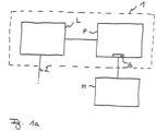
- FIG. 1a shows a schematic of the treatment device 1.
- a laser device L emits the laser beam 2 onto the eye 3.
- the operation of the laser device L is fully automatic, ie the laser device L starts the deflection of the laser beam 2 upon a corresponding start signal and in the process creates cutting surfaces which are constructed in a manner to be described below and which isolate a volume in the cornea.
- the laser device L receives the control data required for operation beforehand from a planning device P as a control data set via unspecified control lines. The transmission takes place before the laser device L is operated.
- communication can also be wireless.
- control data set is transmitted to the treatment device 1 and further preferably, operation of the laser device L is blocked until a valid control data set is available at the laser device L.
- a valid control data set can be a control data set that is in principle suitable for use with the laser device L of the treatment device 1.
- the validity can also be linked to the passing of further tests, for example whether additional information about the treatment device 1, e.g. a device serial number, or the patient, e.g. a patient identification number, stored in the control data set matches other information that was read out on the treatment device or entered separately, for example, as soon as the patient is in the correct position for operation of the laser device L.
- the planning unit P generates the control data set, which is made available to the laser unit L for carrying out the operation, from measurement data and refractive error data that were determined for the eye to be treated. They are fed to the planning unit P via an interface S and, in the embodiment shown, come from a measuring device M that has previously measured the eye of the patient 4. Of course, the measuring device M can transmit the corresponding measurement and refractive error data to the planning device P in any manner.
- the transfer can be carried out using memory chips (e.g. via USB or memory stick), magnetic storage (e.g. floppy disks), wirelessly (e.g. WLAN, UMTS, Bluetooth) or wired (e.g. USB, Firewire, RS232, CAN bus, Ethernet, etc.).
- memory chips e.g. via USB or memory stick
- magnetic storage e.g. floppy disks
- wirelessly e.g. WLAN, UMTS, Bluetooth
- wired e.g. USB, Firewire, RS232, CAN bus, Ethernet, etc.
- a direct radio or wire connection between the measuring device M and the treatment device 1 for data transmission which can be used in one variant, has the advantage that the use of incorrect measurement and refractive error data is excluded with the greatest possible certainty.
- the measurement and refractive error data can also be transferred to the treatment device 1 at the same time.
- the planning device P always generates the control data record belonging to the patient 4, and an erroneous use of an incorrect control data record for a patient 4 is virtually excluded.
- the mode of action of the laser beam 2 is Figure 2 indicated schematically.
- the treatment laser beam 2 is focused into the cornea 5 of the eye 6 by means of an unspecified optic. This creates a focus in the cornea 5 that covers a spot 6 and in which the laser radiation energy density is so high that, in combination with the pulse length, a non-linear effect occurs in the eye.
- each pulse of the pulsed laser radiation 2 can generate an optical breakthrough in the cornea 5 at the respective spot 6, which in turn creates a Figure 2 schematically indicated plasma bubble is initiated.
- This laser pulse separates tissue in the cornea 5. When a plasma bubble is formed, the tissue layer separation covers a larger area than the spot 6 covered by the focus of the laser radiation 2, although the conditions for generating the breakthrough are only achieved in the focus.
- the energy density ie the fluence of the laser radiation, must be above a certain pulse length-dependent threshold value. This connection is known to the expert, for example, from the DE 69500997 T2 known.
- a tissue-separating effect can also be generated by the pulsed laser radiation by emitting several laser radiation pulses in one area, with the spots 6 overlapping for several laser radiation pulses. Several laser radiation pulses then work together to achieve a tissue-separating effect.
- the type of tissue separation used by the treatment device 1 is not relevant for the following description, however, the only important thing is that pulsed treatment laser radiation 2 is used for this purpose.
- a treatment device 1 can be used as described in the WO 2004/032810 A2 is described.
- the pattern specifies target points for the focus position at which one or more laser pulses are emitted, and defines the shape and position of the cutting surface.
- the pattern of the target points is important for the methods and devices explained below and will be described in more detail.
- material is removed from an area within the cornea using pulsed laser radiation 5 by separating tissue layers that isolate the material and then allow the material to be removed.
- Material removal causes a volume change in the cornea, which results in a change in the optical imaging effect of the cornea 5, which is precisely dimensioned so that the previously determined visual impairment is/will be corrected as far as possible.
- the focus of the laser radiation 2 is directed at target points in the cornea 5, usually in an area that lies below the epithelium and Bowman's membrane and above Decemet's membrane and the endothelium.
- the treatment device 1 has a mechanism for adjusting the position of the focus of the laser radiation 2 in the cornea 5. This is shown schematically in Figure 3 shown.
- the laser radiation 2 is, as already mentioned, bundled in a focus 7 in the cornea 5, and the position of the focus 7 in the cornea is adjusted so that energy from laser radiation pulses is introduced into the tissue of the cornea 3 in a focused manner at different points to create the cutting surface.
- the laser radiation 2 is provided by a laser 8 as pulsed radiation.
- the xy scanner 9 thus causes an adjustment of the position of the focus 7 essentially perpendicular to the main direction of incidence of the laser radiation 2 into the cornea 5.
- a z scanner 11 is provided for adjusting the depth, which is designed, for example, as an adjustable telescope.
- the z scanner 11 ensures that the z position of the position of the focus 7, i.e. its position on the optical axis of incidence, is changed.
- the z scanner 11 can be arranged upstream or downstream of the xy scanner 9.
- the coordinates designated below as x, y, z therefore refer to the deflection of the position of the focus 7.
- the xy scanner 9 deflects around axes that are at right angles to each other; rather, any scanner can be used that is able to adjust the focus 7 in a plane in which the axis of incidence of the optical radiation does not lie. Oblique coordinate systems are therefore also possible.
- non-Cartesian coordinate systems can also be used to describe or control the position of the focus 7, as will be explained below.
- Examples of such coordinate systems are spherical coordinates (also called spherical coordinates) and cylindrical coordinates.
- the xy scanner 9 and the z scanner 11 which together implement a concrete example of a three-dimensional focus adjustment device, are controlled by a control unit 12 via unspecified lines.
- the control unit 3 ensures a suitably synchronous operation of the laser 8 and the three-dimensional focus adjustment device, implemented by way of example by the xy scanner 9 and the z scanner 11, so that the position of the focus 7 in the cornea 5 is adjusted in such a way that ultimately a material of a certain volume is isolated, with the subsequent volume removal bringing about a desired correction of the visual impairment.
- the control device 12 works according to predetermined control data, which specify the target points for the focus adjustment.
- the control data is usually summarized in a control data set. In one embodiment, this specifies the coordinates of the target points as a pattern, whereby the order of the target points in the control data set determines the sequence of the focus positions and thus ultimately a trajectory (also referred to here for short as path).
- the control data set contains the target points as concrete control values for the focus position adjustment mechanism, e.g. for the xy scanner 9 and the z scanner 11.
- the target points and preferably also their order in the pattern are determined. The surgical procedure must be planned in advance so that the control data for the treatment device 1 is determined, the application of which then achieves an optimal visual impairment correction for the patient 4.
- Figure 4 shows in sub-figures a), b) and c) the optical conditions on the eye 3 of the patient 4. Without correction of the refractive error, the situation shown in sub-figure a) exists.
- the cornea 5, together with the eye lens 13, focuses an object lying at infinity into a focus F, which lies on the z-axis behind the retina 14.
- the imaging effect is caused on the one hand by the eye lens 13, which is relaxed when the eye is not accommodated, and on the other hand by the eye cornea 5, which is essentially defined by a front surface 15 of the cornea and a back surface 16 of the cornea and also has an imaging effect due to its curvature.
- the optical effect of the cornea 5 is determined by the radius of curvature Rcv of the front surface of the cornea.
- Sub-figure a) shows the refractive error are only examples; the more complex visual impairments mentioned above can actually exist. The following description also applies to them, but the equations given can then sometimes contain an additional angle dependency, even if this is not explicitly stated.
- an auxiliary lens 17 in the form of a pair of glasses is placed in front of the eye 3 at a distance d HS from the vertex of the cornea 5.
- the lens 17 of the glasses is adjusted in its refractive power B BR so that it shifts the far point of the entire system, ie of the glasses and the eye, from the focus point F to the corrected focus point F*, which lies on the retina 14.
- the focus F* is therefore the focus that is obtained after the optical correction, which is shown in part b) of the Figure 4 through the lens 17 of the glasses.
- the radius of curvature Rcv of the front surface 15 of the cornea is modified by the volume removal.
- the cornea 5, reduced by the volume has such a changed imaging effect that the then corrected focus F* is on the retina 14. After the correction, there is a changed front surface 15* of the cornea, and a correction of the refractive error is achieved even without glasses.
- the curvature of the modified corneal front surface 15* to be achieved is determined.
- the starting point is the refractive power of the lens 17 of the glasses, since determining the corresponding parameters is a standard procedure in ophthalmic optics.
- n c is the refractive power of the corneal material.
- the corresponding value is usually 1.376;
- d HS is the distance at which a pair of glasses with the refractive power B BR must be from the corneal vertex in order to produce the desired refractive error correction using glasses;
- B BR is the previously mentioned refractive power of the glasses according to equation (1).
- the information for the refractive power B BR can also cover refractive errors that go beyond a normal spherical or cylindrical correction.
- B BR (and thus automatically also Rcv*) then have additional coordinate dependencies.
- the factor F expresses the optical effect of the change in the thickness of the cornea and can be regarded as a constant factor in a first approximation.
- Rcv* is calculated iteratively by using the difference (Rcv* - Rcv) in the i-th calculation to determine the value (dc* - dc) and applying the resulting result for the change in thickness to the (i+1)-th calculation.
- This limit can be set, for example, using a constant difference that corresponds to an accuracy of the refraction correction that is appropriate for the treatment.
- the boundary surface isolating the volume is now defined for the volume whose removal causes the above change in curvature of the anterior corneal surface 15. It is preferable to take into account that the diameter of the area to be corrected and thus the diameter of the volume to be removed should, if possible, extend over the pupil size in a dark-adapted eye.
- a free surface is defined using numerical methods known to those skilled in the art, which describes a volume whose removal causes the change in curvature. To do this, the change in thickness necessary for the desired curvature modification is determined along the z-axis. This results in the volume as a function of r, ⁇ (in cylindrical coordinates) and from this in turn its boundary surface.
- a simple analytical calculation is provided by the following second variant, in which the boundary surface of the volume is constructed by two partial surfaces, an anterior partial surface located towards the corneal surface 15 and an opposite posterior partial surface.
- the corresponding relationships are shown in Figure 5 .
- the volume 18 is limited to the front surface of the cornea 15 by an anterior cut surface 19, which is located at a constant distance d F below the front surface of the cornea 15.
- This anterior cut surface 19 is also referred to as a flap surface 19 in analogy to laser keratomes, since it is used there, in combination with an opening cut towards the edge, to lift the cornea 5 off a lamella in the form of a "flap" from the underlying cornea 5.
- This type of removal of the previously isolated volume 18 is of course also possible here.
- the anterior cut surface 19 has a curvature that is d F below the anterior corneal surface 15. If this is spherical, a radius of curvature that is d F less than the radius of curvature Rcv can be specified for the flap surface 19.
- a radius of curvature that is d F less than the radius of curvature Rcv can be specified for the flap surface 19.
- the volume 18 to be removed from the cornea 5 is limited by a posterior cutting surface 20, which in principle does not extend to the anterior corneal surface 15 in constant distance.
- the posterior cutting surface 20 will therefore be designed in such a way that the volume 18 is in the form of a lenticule, which is why the posterior cutting surface 20 is also referred to as the lenticule surface 20.
- Figure 5 it is shown as an example as a spherical surface with a radius of curvature R L , whereby of course the center of this curvature does not coincide with the center of curvature of the Figure 5 also spherical anterior corneal surface 15.
- Figure 6 shows the conditions after removal of volume 18.
- the radius of the modified corneal anterior surface 15* is now Rcv* and can be calculated, for example, according to the equations described above.
- the thickness d L of the removed volume 18 is decisive for the radius change, as Figure 7 In this figure, further quantities are shown: the height h F of the spherical cap defined by the anterior cut surface 19, the height h L of the spherical cap defined by the posterior cut surface 20 and the thickness d L of the volume 18 to be removed.
- the posterior cut surface 20 determines the curvature of the anterior corneal surface 15* after removal of the volume 18.
- the posterior cut surface 20 will have an angle-dependent radius of curvature, for example in the case of a refractive error correction that takes cylindrical parameters into account.
- the dependence on ⁇ is eliminated and the lenticule surface 20 is spherical.
- the lenticule surface 20 usually has different radii of curvature on different axes, although these naturally usually have the same vertex.
- ⁇ ⁇ /2
- an additional edge surface can be provided which surrounds the volume 18 in the intersection area of the flap surface 20 and the lenticule surface 19 or connects these surfaces where they do not converge at a given z coordinate.
- the intersection of this edge surface is also carried out with the pulsed laser beam.
- the edge surface can, for example, have a cylindrical shape, but can also have an elliptical shape (in top view) or a conical shape (in side view).
- the design of the volume 18 shown in the figures as being limited by an anterior cutting surface 19 with a constant distance to the anterior surface of the cornea 15 and a posterior cutting surface 20 is only one variant for limiting the volume 18.
- the optical correction is essentially determined by only one surface (the lenticule surface 20), so that the analytical description of the other partial surface of the interface is simple.
- the residual thickness d F between the anterior cut surface 19 and the anterior corneal surface 15 can be set to a constant value of, for example, 50 to 200 ⁇ m. In particular, it can be selected so that the pain-sensitive epithelium remains in the lamella formed by the flap surface 19 under the anterior corneal surface 15.
- the formation of the spherical flap surface 19 is also in continuity with previous keratometer cuts, which is advantageous for the acceptance of the method.
- the volume 18 isolated in this way is then removed from the cornea 5.
- Figure 8 which also shows that the cutting surfaces 19 and 20 are created by the action of the treatment laser beam incident in a focus cone 21, for example by arranging Plasma bubbles, so that in a preferred embodiment the flap cutting surface 19 and the lenticule cutting surface 20 are generated by suitable three-dimensional adjustment of the focus position of the pulsed laser radiation 2.
- both the lenticule surface 20 and the flap surface 19 are created by means of pulsed laser radiation, it is expedient to form the lenticule surface 20 before the flap surface 19, since the optical result for the lenticule surface 20 is better (if not achievable at all) if no change in the cornea 5 has yet occurred above the lenticule surface 20.
- the removal of the volume 18 isolated by the pulsed laser radiation can, as in Figure 8 indicated, can be achieved by an edge cut 22, which allows the volume 18 to be cut in the direction of a Figure 8 drawn arrow 23.
- the edge cut 22 can be designed such that it connects the anterior cut surface 19, i.e. the flap surface 19, in the form of a ring with the front surface of the cornea 15, although the edge cut does not completely run through an angle of 360°.
- the lamella isolated in this way remains connected to the remaining tissue of the cornea 5 in a narrow area.
- This connecting bridge then serves as a joint to fold the otherwise isolated lamella away from the cornea 5 and to be able to remove the already isolated volume 18 that is thus accessible from the rest of the cornea 5.
- the position of the connecting bridge can be specified when generating the control data or the target points. From this point of view, the procedure or device described therefore realizes the isolation of the volume 19 within the cornea 5 and the creation of a lamella connected to the remaining cornea via a tissue bridge as a cover over the volume.
- the lid can be folded down and volume 18 can be removed.
- the target points can now be arranged in a variety of ways.
- special spirals can be used, which, for example, run around a main axis that is essentially perpendicular to the optical axis (z-axis) in the manner of a helical line.
- the use of a scanning pattern that arranges the target points line by line is also known (cf. WO 2005/011545 ).
- the adjustment of the position of the focus in the cornea is carried out by means of the Figure 3 schematically shown three-dimensional deflection device, which is used to adjust the focus in the z-direction the displacement of lenses or other optically effective elements begins.
- the adjustment of lenses or similar is generally not possible as quickly as the pivoting of mirrors, as are generally used in the xy scanner.
- the adjustment speed of the z-scanner usually limits the speed with which the cutting surfaces can be created in the cornea.
- the focus is guided along a spiral path, with one spiral in each of the spatially curved cutting surfaces. While the spiral is being written, the z-scanner is adjusted so that the arms of the spiral follow the spatially curved cutting surface.
- Figure 9 shows an example of a trajectory curve 24 as a spiral, which in the illustration shown is designed as a circular spiral.
- d T denotes the distance between the spiral arms; it is in Figure 10 which shows an enlarged section of the Figure 9
- the trajectory 24 along which the laser focus is adjusted is an elliptical spiral, for which there is naturally no longer a constant distance between the spiral arms.
- a respective trajectory distance d Tb and d Ta can be defined along the main axes a and b, as Figure 11 shows.
- the spots 6 are shown to show the position of the focus for the individual laser pulses.
- the plasma bubbles naturally expand so much after the introduction of the respective laser pulse that the cutting surface is created and the trajectory 24 can then no longer be seen in the cutting surface.
- the volume 18 in the eye should ultimately be defined in the normal state.
- the cut surfaces 19 and 20, as explained so far, relate to the natural eye.
- the treatment device 1 works with a contact lens 25 for reasons of fixation of the eye, which, as in Figure 12 shown, is placed on the anterior corneal surface 15 of the cornea 5.
- the contact glass 25 which is already the subject of several patent publications (for example, see WO 2005/048895 A). However, for the present description of the treatment device 1 or the associated methods for preparing and/or carrying out the surgical procedure, this is only of interest insofar as it gives the anterior corneal surface 15 a defined curvature and, on the other hand, holds the cornea 5 in a predefined position relative to the treatment device 1. With regard to the spherical curvature of the contact surface of the contact glass 25, the approach described here differs significantly from the approach described, for example, in the WO 2003/002008 A which uses a flat contact lens that flattens the cornea.
- the contact lens has another advantage.
- the front surface 15 of the cornea is automatically spherical.
- the anterior cut surface 19, which is at a constant distance below the front surface 15 of the cornea, is therefore also spherical when the contact lens is pressed against it, which leads to considerably simplified control.
- Target points are/are specified for the posterior cut surface, which define a curvature which, when the eye is relaxed, i.e. after the contact lens is removed, extends to the Distance d F to the anterior surface of the cornea must correspond to the desired distance for correcting the refractive error. The same applies to the method for defining the target points and the surgical procedure.
- the depictions in the Figures 13 and 14 show the coordinate transformation that occurs in the eye when the contact lens is put on or taken off. They contain both spherical coordinates (R, ⁇ , ⁇ ) related to the origin of the curved surface (corneal front surface 15 or contact lens underside 26) and cylindrical coordinates (r, z, ⁇ ) related to the vertex of the corneal front surface 15 or contact lens underside 26 defined by the point of passage of the optical axis OA.
- FIG. 15 The pressing of the cornea 5 of the eye 3 against the spherically curved contact lens underside 26 is in Figure 15
- the right-hand illustration shows schematically the state when the contact lens underside 26 is only in contact with the corneal anterior surface 15 at the vertex.
- the corneal anterior surface 15 is schematically shown in Figure 15 drawn as a circle, although of course the spherical curvature is only present in a smaller circular section.
- Pressing the contact glass 25 onto the cornea 5 causes the transition to the state of the left side of the Figure 15 .
- Removing the contact lens 25 causes a relaxation of the eye 3 in the opposite direction of the arrow 27
- v Z t d S ⁇ f L ⁇ d T / 2 ⁇ ⁇ R F 2 ⁇ t ⁇ d S ⁇ f L ⁇ d T / ⁇ 1 2 , where f L is the frequency of the laser pulses of the laser radiation 2. Equation (5) assumes that the z-velocity vz can be freely set and continuously changed.
- the speed at which the z-scanner shifts the focus in the z-direction can only be adjusted within a set of discrete speeds. If you then want to create a certain parabola with a given speed vz, the product d S •d T must be chosen accordingly so that the first square bracket of equation (8) takes on the desired value. The distance between the paths, defined by d T , as well as the spot distance along the path described by ds, can therefore be varied in order to write a certain parabola with a given v z .
- Each of the equations (5), (6)/(7) and (8) can be used to determine the target points and thus to control the focus adjustment, whereby the corresponding spiral shape/surface shape must of course be used as a basis.
- the equations are used for control, this is to be understood in particular that the target points are determined using the equations, which can be done, for example, by evaluating the functional equations at equidistant points in time.
- the speed equations are used in one variant to ensure that the determined target points do not require adjustment speeds that cannot be achieved by the focus adjustment device.
- the lenticule surface 20 is spherical if no cylinder correction is to be carried out.
- the control according to equations (4)/(5) or (6)/(7) is therefore used to generate this sphere.
- a sphere can also be approximated by a paraboloid. It is therefore provided in one variant to approximate a sphere in a manner known to those skilled in the art by a paraboloid and to carry out the control according to equation (8).
- the lenticule surface 20 changes.
- the lenticule surface 20 must have the curvature of the corrected corneal anterior surface 15* in the coordinate system of the contact lens 25. It cannot be related to a center of curvature that coincides with the center of curvature of the contact lens.
- the curvature defined according to equation (2) is therefore converted with respect to the suction transformation.
- the radius of curvature defined in equation (2) is of course a function of ⁇ .
- two radii of curvature r a and r b can be specified: one on the axis ⁇ of the cylindrical refractive error and one for an axis perpendicular to it.
- the approximation is made by looking for a parabola for each of the two radii of curvature that runs through both the vertex of the lenticule surface 20 and through a point that is as close to the edge as possible.
- the corresponding relationships in the coordinate system of the eye are shown in Figure 16 .
- This figure shows the spherical lenticule surface 20 before the contact pressure transformation.
- the sections through the toroidal lenticule surface 20 in the generalized case are superimposed along the two semi-axes a and b.
- the corresponding curves are designated A and B respectively and are circular with a radius of curvature r a and r b respectively.
- an edge point T is described in cylindrical coordinates by the corresponding radius r and the height h, whereby these parameters are related to the vertex S, which is identical for the two semi-axis sections.
- the point T a is therefore characterized by the radius r a and the height h a .
- T b is also characterized by the radius r a and the height h a .
- the parabola parameters h a for the parabola along the major semi-axis a and k b for the parabola along the minor semi-axis b thus obtained define the paraboloid, which is then written by adjusting the focus point in the z-direction, for example by means of a constant z-feed (cf. equation (7)) or by selecting the z-speed from a set of discrete speeds (modification of equation (7)).
- the parabola parameters in Figure 16 The sections of the toriodal lenticule surface 20 along the small main axis b and the large main axis a shown refer to the representation in the coordinate system of the eye.
- z(S) denotes the z-coordinate of the point S. If the origin of the coordinate system is placed at the vertex, as in the previous figures, the z-coordinate is zero.
- the coordinates z(T a ) or z(T b ) as well as r(T a ) or r(T b ) are the z- or r-coordinates of the corresponding point T a or T b in the cylindrical coordinate system.
- the mean track or spot distance is maintained by the simultaneous compression and stretching. If one were to compress or stretch in only one direction, the mean distance would change.
- the ellipticity e' is the ellipticity of the transformed toriodal lenticule surface 20.
- the parameters k b ' and k a ' are given by equations (11) and (12), respectively for the transformed points S', T a ' and T b '.
- the parabola parameters result from the fact that here the circular spiral with the radius r 0 , from which the lenticule surface 20 is constructed, should be an arithmetic or geometric mean of the curvatures of the major and minor semi-axes of the paraboloid.
- This focus position error is a property of the optical system, ie it is based on the optical implementation used. It is essentially caused by the optical design. Due to finite manufacturing accuracy within the permitted tolerance, the focus position error is also device-specific. It is therefore appropriately determined independently for each device.
- the focus position error is taken into account by a generally non-linear transformation (hereinafter also referred to as NL transformation). It is therefore not possible to carry out the NL transformation by modifying the trajectory parameters.
- the focus position error is expressed by a correction table or a correction function. This comes from a measurement of the optics of the treatment device 1. The measurement can be device-type-related or device-specific. The correction function can be obtained from an interpolation of the measurement results, e.g. using polynomials or splines.
- the focus position error is usually rotationally symmetrical with respect to the optical axis. In cylindrical coordinates, it then only depends on r and z.
- the points previously calculated using the trajectories are pre-distorted in the NL transformation so that they are located exactly at the desired location after the laser spots are introduced using the optical system that has the focus position error.
- the application of the pre-distorted coordinates therefore compensates for the focus position error that occurs in the optical system.
- the effect of the predistortion to compensate for the focus position error is in Figure 18 It shows the contact glass bottom 26, which is spherical in the present example, but can also have a different shape. Due to the predistortion, it becomes a transformed contact glass sphere 26 ⁇ .
- the calculated trajectories are converted into individual target point coordinates for the spots, which are then used in the Figure 18 by the correction transformation symbolized by K(r, z), i.e. the NL transformation. If the focus position error is specified as a function K, the coordinate of each target point only needs to be evaluated with the function in order to obtain the shift or the transformed coordinate.
- the coordinates for the target points obtained in this way must still be converted into control signals for the three-dimensional deflection unit, e.g. the xy scanner and the z scanner.
- the three-dimensional deflection unit e.g. the xy scanner and the z scanner.
- a corresponding functional relationship or a corresponding characteristic map is used that is known for the scanner and has been determined in advance if necessary.
- the response function was previously determined for the xy scanners, which are implemented as galvanometer mirrors in the example. Applying a frequency sweep to the galvanometer mirrors and measuring the actual galvanometer movement provide an amplitude and phase response function. These are taken into account when determining the control signals.
- the scanner is not given a signal for the target to be approached for each point.
- the control unit 12 specifies support points that characterize the path of the scanner. The number of points is thus significantly reduced. This can be used to advantage in the NL transformation by subjecting only those target points for the trajectories to the transformation that are to be support points for control.
- the evaluation of the functional equations is therefore carried out using a time interval that is shorter than the time interval of the laser pulses.
- the trajectory points are filtered, which provides the aforementioned support points, i.e. points at a frequency of the scanner control for transformation. Equivalent to such filtering is an evaluation of the functionally described trajectories at support points spaced apart according to the scanner control. This is where another advantage of the function-based approach described here becomes apparent: the decision as to which points are target points for controlling the focus adjustment device only has to be made before the NL transformation. Before this, only the trajectory parameters have to be converted appropriately. Only then are data sets with a large number of points available.
- the support points thus define target points that form only a subset of the set of points to which a laser pulse is emitted. This is in Figure 10 illustrated in which those spots 6, which are a target point 28 in the control data set, are marked as black filled circles.
- This procedure also has the advantage that the maximum frequency fs that occurs when the scanner is controlled is much lower than the laser pulse frequency f p .
- the maximum frequency fs that occurs when the scanner is controlled is much lower than the laser pulse frequency f p .
- a control frequency of 20 kHz and a laser pulse frequency of 200 kHz there are one or more spots 6 to which pulsed laser radiation is also emitted.
- the preliminary procedure that was carried out to provide the corresponding control values or parameters is completed. Human involvement, and in particular the involvement of a doctor or surgeon, is not required for this preliminary procedure.
- the procedure is carried out by the control device 12 without the intervention of a doctor. His presence is only required for the subsequent surgical intervention.
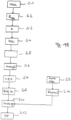
- step S1 the eye 3 is measured. Correction parameters are obtained for the visual impairment of the patient 4, such as those used for conventional glasses.
- the parameters established in step S2 are then used in a step S3 to determine the new curvature of the cornea 5 required for the correction.
- step S3 the volume that must be removed from the cornea is determined in S4. This is usually done by determining the lenticule area 20 and the flap area 19 in a step S5. Once the corresponding Once functional descriptions of these surfaces have been obtained, the suction transformation that occurs when the eye is sucked onto the contact lens is taken into account in step S6.
- step S7 the coordinates of the trajectories from which the cutting surfaces are constructed are determined. This is indicated schematically in step S7 by the parameters r, ⁇ , z. At the end of step S7, there is a point pattern with the coordinates of the spots that a laser radiation pulse is to act on.
- the density of the target points can already be reduced to simplify the computational effort by not specifying a support point for each spot exposed to laser radiation when controlling the scanner.
- step S11 The coordinate set obtained in this way is then transformed again in step S8 to take the focus position error into account.
- the actual control parameters are then determined, using a response function obtained in a step S10 from a previous measurement (step S9) of the amplitude and frequency behavior of the scanner.
- control parameters determined in this way are then used in step S12 to carry out the actual operation, in which additional spots are now preferably exposed to laser radiation pulses between the individual support points on which the control of the scanner is based.
Landscapes
- Health & Medical Sciences (AREA)
- Ophthalmology & Optometry (AREA)
- Heart & Thoracic Surgery (AREA)
- Animal Behavior & Ethology (AREA)
- Optics & Photonics (AREA)
- Surgery (AREA)
- Engineering & Computer Science (AREA)
- Biomedical Technology (AREA)
- Physics & Mathematics (AREA)
- Vascular Medicine (AREA)
- Life Sciences & Earth Sciences (AREA)
- Nuclear Medicine, Radiotherapy & Molecular Imaging (AREA)
- General Health & Medical Sciences (AREA)
- Public Health (AREA)
- Veterinary Medicine (AREA)
- Laser Surgery Devices (AREA)
- Electrotherapy Devices (AREA)
- Exchange Systems With Centralized Control (AREA)
- Paper (AREA)
Claims (12)
- Appareil de traitement pour la correction chirurgicale d'un défaut de vision d'un oeil (3) d'un patient (4), qui possède un dispositif laser (L) qui sépare des tissus cornéens par irradiation d'un rayonnement laser focalisé pulsé (2), un verre de contact (25) pour la mise en place et la fixation de l'oeil (3), qui confère une forme sphérique connue à la face antérieure de la cornée (15), et un dispositif de planification (P), le dispositif de planification (P)- possède une interface (S) pour l'apport de données de mesure concernant des paramètres de l'œil (3) et de données de défauts visuels concernant les défauts visuels de l'œil (3) à corriger,- définit, à partir des données de mesure et d'amétropie fournies, un volume (18) qui se trouve à l'intérieur de la cornée (5) et dont l'enlèvement de la cornée (5) provoque la correction souhaitée de l'amétropie,- détermine une surface limite (19, 20) qui délimite le volume défini (18) à l'intérieur de la cornée (5), et- pour cette surface limite (19, 20), on génère un jeu de données de commande pour commander le dispositif laser (L), qui définit dans la cornée (5) un modèle tridimensionnel de points cibles (28) qui se trouvent dans la surface limite (19, 20) et qui sont disposés de telle sorte que la surface limite (19, 20), après irradiation du rayonnement laser pulsé (2) selon le jeu de données de commande, est réalisée sous forme de surface de coupe qui isole le volume défini (18) dans la cornée (5) et le rend ainsi éliminable,
caractérisé en ce que- le dispositif de planification (P) compose l'interface d'une surface partielle antérieure (19) et d'une surface partielle postérieure (20), la surface partielle antérieure (19) étant un paraboloïde approximant une sphère située à une distance constante de la surface antérieure de la cornée (15), et la surface partielle postérieure (20) n'étant pas à une distance constante de la surface antérieure de la cornée (15). - Appareil de traitement selon la revendication 1, caractérisé en ce que les données relatives à l'amétropie comprennent la puissance de réfraction BBR d'une paire de lunettes (17) adaptée à la correction de l'amétropie, ainsi que la distance dHS à laquelle la paire de lunettes (17) avec la puissance de réfraction BBR doit se trouver devant le sommet de la cornée pour obtenir la correction souhaitée de l'amétropie au moyen de la paire de lunettes (17).
- Appareil de traitement selon la revendication 2, caractérisé en ce que le dispositif de planification (P) définit le volume (18) de telle sorte que la surface antérieure de la cornée (15*) de l'oeil (3) prenne un rayon de courbure RCV* après retrait du volume (18), en utilisant l'équation suivante


- Appareil de traitement selon l'une des revendications précédentes, caractérisé en ce que le dispositif laser (L) possède un dispositif de réglage de focalisation tridimensionnel (28) qui déplace le rayonnement laser focalisé (2) le long d'une trajectoire (24) sur le modèle des points cibles (28) et délivre des impulsions du rayonnement laser pulsé (2) dans la cornée (5) également sur des points (6) qui se trouvent sur la trajectoire (24) entre les points cibles (28).
- Appareil de traitement selon l'une des revendications précédentes, caractérisé en ce qu'il possède un dispositif de réglage du foyer tridimensionnel et en ce que l'appareil de commande (12) est configuré pour commander le dispositif de réglage du foyer tridimensionnel (9, 11) de manière à déplacer le foyer (7) du rayonnement laser focalisé (2) le long d'une trajectoire, l'appareil de traitement appliquant le rayonnement laser pulsé avec un réglage continu de la position du foyer et des coordonnées cylindriques ou sphériques étant utilisées pour commander la position du foyer (7).
- Appareil de traitement selon l'une des revendications précédentes, caractérisé en ce que l'interface (19, 20) délimite un volume (18) à l'intérieur de la cornée (5), l'isole dans la cornée (5) et le rend ainsi amovible, et le volume (18) recouvre la pupille de l'œil (3) adapté à l'obscurité.
- Appareil de traitement selon l'une des revendications précédentes, caractérisé en ce qu'il est prévu une liaison de données ou un support de données pour transmettre les données de commande du dispositif de planification (P) au dispositif laser (L).
- Appareil de traitement selon l'une des revendications précédentes, caractérisé en ce qu'un dispositif de mesure (M) destiné à déterminer des données de mesure concernant des paramètres de l'œil (3) et des données de défaut de vision concernant le défaut de vision de l'œil (3) à corriger est directement relié à l'appareil de traitement (1).
- Appareil de traitement selon l'une des revendications précédentes, caractérisé en ce qu'il possède un dispositif d'affichage pour représenter visuellement les données de commande et un dispositif d'entrée pour modifier ultérieurement les données de commande.
- Appareil de traitement selon l'une quelconque des revendications précédentes, caractérisé en ce qu'il possède un dispositif de réglage de foyer tridimensionnel et en ce que l'appareil de commande (12) est configuré pour commander le dispositif de réglage de foyer tridimensionnel (9, 11) de manière à déplacer le foyer (7) du rayonnement laser focalisé (2) le long d'une trajectoire possédant une courbe en forme de spirale.
- Appareil de traitement selon l'une des revendications précédentes, caractérisé en ce que la déformation de la cornée qui se produit lors de l'utilisation du verre de contact curviligne (25) est prise en compte dans l'enregistrement de commande, afin qu'une interface souhaitée (19, 20) soit présente dans l'œil (3) non déformé par le verre de contact (25), indépendamment du degré de déformation.
- Appareil de traitement selon l'une des revendications précédentes, caractérisé en ce que le dispositif laser (L) focalise, au moyen d'une optique, le rayonnement laser (2) en un foyer (7) qui recouvre un spot (6), et émet des impulsions du rayonnement laser (2) dans une zone de la cornée (5), les spots (6) se chevauchant pour plusieurs des impulsions.
Applications Claiming Priority (7)
| Application Number | Priority Date | Filing Date | Title |
|---|---|---|---|
| US85820106P | 2006-11-10 | 2006-11-10 | |
| DE102006053118.3A DE102006053118B4 (de) | 2006-11-10 | 2006-11-10 | Planungseinrichtung zum Vorbereiten von Steuerdaten für eine Behandlungsvorrichtung zur operativen Fehlsichtigkeitskorrektur, Behandlungsvorrichtung zur operativen Fehlsichtigkeitskorrektur und Verfahren zum Vorbereiten von Steuerdaten dafür |
| EP10173881.3A EP2298255B1 (fr) | 2006-11-10 | 2007-11-12 | Dispositif de planification destiné à préparer des données de commande pour un dispositif de traitement de correction d'un défaut visuel par opération, dispositif de traitement de correction d'un défaut visuel par opération et procédé de préparation de données de commande à cet effet |
| EP15200150.9A EP3037077B1 (fr) | 2006-11-10 | 2007-11-12 | Systeme de preparation de donnees de commande pour un dispositif de traitement destine a la correction operatoire d'ametropie |
| EP20215994.3A EP3831348B1 (fr) | 2006-11-10 | 2007-11-12 | Dispositif de traitement laser destiné à la correction opérationnelle des troubles de la vue |
| EP07846562A EP2086482B1 (fr) | 2006-11-10 | 2007-11-12 | Dispositif de planification destiné à préparer des données de commande pour un dispositif de traitement de correction d'un défaut visuel par opération, dispositif de traitement de correction d'un défaut visuel par opération et procédé de préparation de do |
| PCT/EP2007/009779 WO2008055706A1 (fr) | 2006-11-10 | 2007-11-12 | Dispositif de planification destiné à préparer des données de commande pour un dispositif de traitement de correction d'un défaut visuel par opération, dispositif de traitement de correction d'un défaut visuel par opération et procédé de préparation de do |
Related Parent Applications (4)
| Application Number | Title | Priority Date | Filing Date |
|---|---|---|---|
| EP10173881.3A Division EP2298255B1 (fr) | 2006-11-10 | 2007-11-12 | Dispositif de planification destiné à préparer des données de commande pour un dispositif de traitement de correction d'un défaut visuel par opération, dispositif de traitement de correction d'un défaut visuel par opération et procédé de préparation de données de commande à cet effet |
| EP07846562A Division EP2086482B1 (fr) | 2006-11-10 | 2007-11-12 | Dispositif de planification destiné à préparer des données de commande pour un dispositif de traitement de correction d'un défaut visuel par opération, dispositif de traitement de correction d'un défaut visuel par opération et procédé de préparation de do |
| EP15200150.9A Division EP3037077B1 (fr) | 2006-11-10 | 2007-11-12 | Systeme de preparation de donnees de commande pour un dispositif de traitement destine a la correction operatoire d'ametropie |
| EP20215994.3A Division EP3831348B1 (fr) | 2006-11-10 | 2007-11-12 | Dispositif de traitement laser destiné à la correction opérationnelle des troubles de la vue |
Publications (3)
| Publication Number | Publication Date |
|---|---|
| EP4342436A2 EP4342436A2 (fr) | 2024-03-27 |
| EP4342436A3 EP4342436A3 (fr) | 2024-05-29 |
| EP4342436B1 true EP4342436B1 (fr) | 2025-01-15 |
Family
ID=39022338
Family Applications (5)
| Application Number | Title | Priority Date | Filing Date |
|---|---|---|---|
| EP20215994.3A Active EP3831348B1 (fr) | 2006-11-10 | 2007-11-12 | Dispositif de traitement laser destiné à la correction opérationnelle des troubles de la vue |
| EP24150966.0A Active EP4342436B1 (fr) | 2006-11-10 | 2007-11-12 | Dispositif de traitement laser destiné à la correction opérationnelle des troubles de la vue |
| EP07846562A Active EP2086482B1 (fr) | 2006-11-10 | 2007-11-12 | Dispositif de planification destiné à préparer des données de commande pour un dispositif de traitement de correction d'un défaut visuel par opération, dispositif de traitement de correction d'un défaut visuel par opération et procédé de préparation de do |
| EP15200150.9A Active EP3037077B1 (fr) | 2006-11-10 | 2007-11-12 | Systeme de preparation de donnees de commande pour un dispositif de traitement destine a la correction operatoire d'ametropie |
| EP10173881.3A Active EP2298255B1 (fr) | 2006-11-10 | 2007-11-12 | Dispositif de planification destiné à préparer des données de commande pour un dispositif de traitement de correction d'un défaut visuel par opération, dispositif de traitement de correction d'un défaut visuel par opération et procédé de préparation de données de commande à cet effet |
Family Applications Before (1)
| Application Number | Title | Priority Date | Filing Date |
|---|---|---|---|
| EP20215994.3A Active EP3831348B1 (fr) | 2006-11-10 | 2007-11-12 | Dispositif de traitement laser destiné à la correction opérationnelle des troubles de la vue |
Family Applications After (3)
| Application Number | Title | Priority Date | Filing Date |
|---|---|---|---|
| EP07846562A Active EP2086482B1 (fr) | 2006-11-10 | 2007-11-12 | Dispositif de planification destiné à préparer des données de commande pour un dispositif de traitement de correction d'un défaut visuel par opération, dispositif de traitement de correction d'un défaut visuel par opération et procédé de préparation de do |
| EP15200150.9A Active EP3037077B1 (fr) | 2006-11-10 | 2007-11-12 | Systeme de preparation de donnees de commande pour un dispositif de traitement destine a la correction operatoire d'ametropie |
| EP10173881.3A Active EP2298255B1 (fr) | 2006-11-10 | 2007-11-12 | Dispositif de planification destiné à préparer des données de commande pour un dispositif de traitement de correction d'un défaut visuel par opération, dispositif de traitement de correction d'un défaut visuel par opération et procédé de préparation de données de commande à cet effet |
Country Status (4)
| Country | Link |
|---|---|
| EP (5) | EP3831348B1 (fr) |
| AT (1) | ATE478642T1 (fr) |
| DE (2) | DE502007014535C5 (fr) |
| WO (1) | WO2008055706A1 (fr) |
Families Citing this family (13)
| Publication number | Priority date | Publication date | Assignee | Title |
|---|---|---|---|---|
| EP3831348B1 (fr) | 2006-11-10 | 2024-01-10 | Carl Zeiss Meditec AG | Dispositif de traitement laser destiné à la correction opérationnelle des troubles de la vue |
| DE102009005482A1 (de) | 2009-01-21 | 2010-07-22 | Carl Zeiss Meditec Ag | Vorrichtung und Verfahren zum Erzeugen von Steuerdaten zur operativen Fehlsichtigkeitskorrektur eines Auges |
| EP2633841B1 (fr) | 2012-02-28 | 2017-08-16 | Ziemer Ophthalmic Systems AG | Dispositif de traitement de tissus oculaires par rayon laser à impulsion |
| DE102013204496A1 (de) | 2013-03-14 | 2014-09-18 | Carl Zeiss Meditec Ag | Erzeugung gekrümmter Schnitte im Inneren der Augenhornhaut |
| US10772763B2 (en) | 2015-08-31 | 2020-09-15 | Cesar C. Carriazo | Treatment apparatus for correcting a refractive error of an eye |
| EP3135261B1 (fr) * | 2015-08-31 | 2021-01-27 | Cesar C. Carriazo | Appareil de traitement pour corriger une erreur de réfraction d'un oeil |
| US11065156B2 (en) | 2016-06-29 | 2021-07-20 | Amo Development, Llc | Lenticular laser incision for low myopia and/or hyperopia patients |
| DE102016116267B4 (de) | 2016-08-01 | 2025-11-13 | Carl Zeiss Meditec Ag | Vorrichtung zur operativen Fehlsichtigkeitskorrektur eines Auges und Verfahren zum Erzeugen von Steuerdaten hierfür |
| DE102017209574A1 (de) * | 2017-06-07 | 2018-12-13 | Francesco Ferrari | Vorrichtungen und Verfahren zur Vorbereitung und Durchführung von cornealen Tattoos |
| DE102019213869A1 (de) | 2018-09-20 | 2020-03-26 | Carl Zeiss Meditec Ag | Erzeugung von Schnitten im Inneren des Auges |
| DE102019103851B4 (de) * | 2019-02-15 | 2023-03-09 | Schwind Eye-Tech-Solutions Gmbh | Verfahren zur Steuerung eines augenchirurgischen Lasers und Behandlungsvorrichtung |
| DE102019122166A1 (de) * | 2019-08-19 | 2021-02-25 | Schwind Eye-Tech-Solutions Gmbh | Verfahren zur Steuerung eines augenchirurgischen Lasers und Behandlungsvorrichtung |
| DE102024114314A1 (de) | 2024-05-22 | 2025-11-27 | Carl Zeiss Meditec Ag | Bestimmen eines zur Fehlsichtigkeitskorrektur in die Hornhaut eines Auges einzufügenden Implantats |
Citations (4)
| Publication number | Priority date | Publication date | Assignee | Title |
|---|---|---|---|---|
| EP0296982B1 (fr) | 1987-06-25 | 1993-09-15 | Hanna Khalil | Dispositif de correction de la forme d'un objet par un traitement laser |
| WO1998018522A1 (fr) | 1996-10-28 | 1998-05-07 | Lasersight Technologies, Inc. | Correction combinee de la myopie astigmatique ou hypermetropie par ablation laser |
| US20040243112A1 (en) | 2003-06-02 | 2004-12-02 | Mark Bendett | Apparatus and method for ophthalmologic surgical procedures using a femtosecond fiber laser |
| WO2005011547A1 (fr) | 2003-07-25 | 2005-02-10 | Carl Zeiss Meditec Ag | Dispositif et procede pour former des surfaces de coupe courbes dans une matiere transparente |
Family Cites Families (20)
| Publication number | Priority date | Publication date | Assignee | Title |
|---|---|---|---|---|
| US6099522A (en) * | 1989-02-06 | 2000-08-08 | Visx Inc. | Automated laser workstation for high precision surgical and industrial interventions |
| US5984916A (en) | 1993-04-20 | 1999-11-16 | Lai; Shui T. | Ophthalmic surgical laser and method |
| DE69232640T2 (de) | 1991-11-06 | 2003-02-06 | Shui T Lai | Vorrichtung für hornhautchirurgie |
| US6090100A (en) * | 1992-10-01 | 2000-07-18 | Chiron Technolas Gmbh Ophthalmologische Systeme | Excimer laser system for correction of vision with reduced thermal effects |
| US5549632A (en) | 1992-10-26 | 1996-08-27 | Novatec Laser Systems, Inc. | Method and apparatus for ophthalmic surgery |
| US5656186A (en) | 1994-04-08 | 1997-08-12 | The Regents Of The University Of Michigan | Method for controlling configuration of laser induced breakdown and ablation |
| US6110166A (en) * | 1995-03-20 | 2000-08-29 | Escalon Medical Corporation | Method for corneal laser surgery |
| US6129722A (en) * | 1999-03-10 | 2000-10-10 | Ruiz; Luis Antonio | Interactive corrective eye surgery system with topography and laser system interface |
| AU772600B2 (en) * | 1999-10-21 | 2004-05-06 | Nidek Co., Ltd. | Amount-of-cornea-to-be-excised determining device and cornea surgery device |
| US6923802B2 (en) * | 2000-03-13 | 2005-08-02 | Memphis Eye & Cataract Assoc. | System for generating ablation profiles for laser refractive eye surgery |
| US6899707B2 (en) | 2001-01-29 | 2005-05-31 | Intralase Corp. | Applanation lens and method for ophthalmic surgical applications |
| US6992765B2 (en) * | 2002-10-11 | 2006-01-31 | Intralase Corp. | Method and system for determining the alignment of a surface of a material in relation to a laser beam |
| DE10332815B4 (de) | 2003-07-18 | 2020-10-22 | Carl Zeiss Meditec Ag | Verfahren und Vorrichtung zum Ausbilden gekrümmter Schnittflächen in einem transparenten Material |
| DE10334108B4 (de) | 2003-07-25 | 2018-05-09 | Carl Zeiss Meditec Ag | Vorrichtung zum Ausbilden einer geschlossenen, gekrümmten Schnittfläche |
| DE10334109A1 (de) * | 2003-07-25 | 2005-02-17 | Carl Zeiss Meditec Ag | Verfahren und Vorrichtung zum Ausbilden von Schnittflächen in einem transparenten Material |
| DE10354025B4 (de) | 2003-11-19 | 2022-03-24 | Carl Zeiss Meditec Ag | Adapter zum mechanischen Koppeln einer Laserbearbeitungsvorrichtung mit einem Objekt |
| US7296893B2 (en) * | 2004-03-03 | 2007-11-20 | Visx, Incorporated | Transformation methods of wavefront maps from one vertex distance to another |
| ES2371407T3 (es) * | 2005-05-02 | 2012-01-02 | Schwind Eye-Tech-Solutions Gmbh & Co. Kg | Procedimiento para el mando de un láser para la ablación de una capa de córnea. |
| US8182471B2 (en) * | 2006-03-17 | 2012-05-22 | Amo Manufacturing Usa, Llc. | Intrastromal refractive correction systems and methods |
| EP3831348B1 (fr) | 2006-11-10 | 2024-01-10 | Carl Zeiss Meditec AG | Dispositif de traitement laser destiné à la correction opérationnelle des troubles de la vue |
-
2007
- 2007-11-12 EP EP20215994.3A patent/EP3831348B1/fr active Active
- 2007-11-12 EP EP24150966.0A patent/EP4342436B1/fr active Active
- 2007-11-12 AT AT07846562T patent/ATE478642T1/de active
- 2007-11-12 EP EP07846562A patent/EP2086482B1/fr active Active
- 2007-11-12 WO PCT/EP2007/009779 patent/WO2008055706A1/fr not_active Ceased
- 2007-11-12 DE DE502007014535.1A patent/DE502007014535C5/de active Active
- 2007-11-12 EP EP15200150.9A patent/EP3037077B1/fr active Active
- 2007-11-12 DE DE502007004877T patent/DE502007004877D1/de active Active
- 2007-11-12 EP EP10173881.3A patent/EP2298255B1/fr active Active
Patent Citations (4)
| Publication number | Priority date | Publication date | Assignee | Title |
|---|---|---|---|---|
| EP0296982B1 (fr) | 1987-06-25 | 1993-09-15 | Hanna Khalil | Dispositif de correction de la forme d'un objet par un traitement laser |
| WO1998018522A1 (fr) | 1996-10-28 | 1998-05-07 | Lasersight Technologies, Inc. | Correction combinee de la myopie astigmatique ou hypermetropie par ablation laser |
| US20040243112A1 (en) | 2003-06-02 | 2004-12-02 | Mark Bendett | Apparatus and method for ophthalmologic surgical procedures using a femtosecond fiber laser |
| WO2005011547A1 (fr) | 2003-07-25 | 2005-02-10 | Carl Zeiss Meditec Ag | Dispositif et procede pour former des surfaces de coupe courbes dans une matiere transparente |
Also Published As
| Publication number | Publication date |
|---|---|
| ATE478642T1 (de) | 2010-09-15 |
| EP4342436A3 (fr) | 2024-05-29 |
| DE502007014535C5 (de) | 2025-02-27 |
| EP2086482A1 (fr) | 2009-08-12 |
| EP2298255A1 (fr) | 2011-03-23 |
| WO2008055706A1 (fr) | 2008-05-15 |
| EP3037077B1 (fr) | 2020-12-30 |
| EP2298255B1 (fr) | 2016-01-27 |
| EP2086482B1 (fr) | 2010-08-25 |
| EP3831348B1 (fr) | 2024-01-10 |
| EP4342436A2 (fr) | 2024-03-27 |
| DE502007004877D1 (de) | 2010-10-07 |
| EP3831348A1 (fr) | 2021-06-09 |
| EP3037077A1 (fr) | 2016-06-29 |
Similar Documents
| Publication | Publication Date | Title |
|---|---|---|
| EP4342436B1 (fr) | Dispositif de traitement laser destiné à la correction opérationnelle des troubles de la vue | |
| EP2211803B1 (fr) | Dispositif de traitement permettant la correction chirurgicale de l'amétropie d'un oeil et procédé de génération de données de commande associées | |
| EP2389147B1 (fr) | Dispositif et procédé de production de données de commande pour la correction opératoire d'un défaut de vision d'un oeil | |
| EP2211804B1 (fr) | Dispositif de traitement permettant la correction chirurgicale de l'amétropie d'un oeil et procédé de génération de données de commande associées | |
| EP2088978B1 (fr) | Dispositif de traitement de correction d'un défaut visuel de l'oeil par opération et procédé de production de données de commande pour ce dispositif | |
| DE102018208014A1 (de) | Planungseinrichtung für eine Astigmatismus-Korrektur | |
| DE102006053118B4 (de) | Planungseinrichtung zum Vorbereiten von Steuerdaten für eine Behandlungsvorrichtung zur operativen Fehlsichtigkeitskorrektur, Behandlungsvorrichtung zur operativen Fehlsichtigkeitskorrektur und Verfahren zum Vorbereiten von Steuerdaten dafür | |
| DE102006053120A1 (de) | Behandlungsvorrichtung zur operativen Fehlsichtigkeitskorrektur eines Auges, Verfahren zum Erzeugen von Steuerdaten dafür und Verfahren zur operativen Fehlsichtigkeitskorrektur eines Auges | |
| EP2088977B1 (fr) | Dispositif de traitement de correction d'un défaut visuel de l'oeil par opération et procédé de production de données de commande pour correction d'un défaut visuel de l'oeil | |
| EP2086483B1 (fr) | Dispositif de traitement de correction d'un défaut visuel de l'oeil par opération et procédé de production de données de commande pour ce dispositif | |
| DE102006053119A1 (de) | Behandlungsvorrichtung zur operativen Fehlsichtigkeitskorrektur eines Auges, Verfahren zum Erzeugen von Steuerdaten dafür und Verfahren zur operativen Fehlsichtigkeitskorrektur | |
| DE102007063962B4 (de) | Behandlungsvorrichtung zur operativen Fehlsichtigkeitskorrektur eines Auges und Verfahren zum Erzeugen von Steuerdaten dafür |
Legal Events
| Date | Code | Title | Description |
|---|---|---|---|
| PUAI | Public reference made under article 153(3) epc to a published international application that has entered the european phase |
Free format text: ORIGINAL CODE: 0009012 |
|
| STAA | Information on the status of an ep patent application or granted ep patent |
Free format text: STATUS: THE APPLICATION HAS BEEN PUBLISHED |
|
| AC | Divisional application: reference to earlier application |
Ref document number: 2086482 Country of ref document: EP Kind code of ref document: P Ref document number: 2298255 Country of ref document: EP Kind code of ref document: P Ref document number: 3037077 Country of ref document: EP Kind code of ref document: P Ref document number: 3831348 Country of ref document: EP Kind code of ref document: P |
|
| AK | Designated contracting states |
Kind code of ref document: A2 Designated state(s): AT BE BG CH CY CZ DE DK EE ES FI FR GB GR HU IE IS IT LI LT LU LV MC MT NL PL PT RO SE SI SK TR |
|
| REG | Reference to a national code |
Ref country code: DE Ref legal event code: R079 Ref document number: 502007017003 Country of ref document: DE Free format text: PREVIOUS MAIN CLASS: A61F0009009000 Ipc: A61F0009010000 Ref country code: DE Ref legal event code: R079 Free format text: PREVIOUS MAIN CLASS: A61F0009009000 Ipc: A61F0009010000 |
|
| PUAL | Search report despatched |
Free format text: ORIGINAL CODE: 0009013 |
|
| STAA | Information on the status of an ep patent application or granted ep patent |
Free format text: STATUS: REQUEST FOR EXAMINATION WAS MADE |
|
| AK | Designated contracting states |
Kind code of ref document: A3 Designated state(s): AT BE BG CH CY CZ DE DK EE ES FI FR GB GR HU IE IS IT LI LT LU LV MC MT NL PL PT RO SE SI SK TR |
|
| RIC1 | Information provided on ipc code assigned before grant |
Ipc: A61F 9/009 20060101ALI20240424BHEP Ipc: A61F 9/008 20060101ALI20240424BHEP Ipc: A61F 9/01 20060101AFI20240424BHEP |
|
| 17P | Request for examination filed |
Effective date: 20240503 |
|
| RBV | Designated contracting states (corrected) |
Designated state(s): AT BE BG CH CY CZ DE DK EE ES FI FR GB GR HU IE IS IT LI LT LU LV MC MT NL PL PT RO SE SI SK TR |
|
| GRAP | Despatch of communication of intention to grant a patent |
Free format text: ORIGINAL CODE: EPIDOSNIGR1 |
|
| STAA | Information on the status of an ep patent application or granted ep patent |
Free format text: STATUS: GRANT OF PATENT IS INTENDED |
|
| INTG | Intention to grant announced |
Effective date: 20241004 |
|
| GRAJ | Information related to disapproval of communication of intention to grant by the applicant or resumption of examination proceedings by the epo deleted |
Free format text: ORIGINAL CODE: EPIDOSDIGR1 |
|
| STAA | Information on the status of an ep patent application or granted ep patent |
Free format text: STATUS: REQUEST FOR EXAMINATION WAS MADE |
|
| GRAP | Despatch of communication of intention to grant a patent |
Free format text: ORIGINAL CODE: EPIDOSNIGR1 |
|
| STAA | Information on the status of an ep patent application or granted ep patent |
Free format text: STATUS: GRANT OF PATENT IS INTENDED |
|
| GRAS | Grant fee paid |
Free format text: ORIGINAL CODE: EPIDOSNIGR3 |
|
| TPAC | Observations filed by third parties |
Free format text: ORIGINAL CODE: EPIDOSNTIPA |
|
| INTC | Intention to grant announced (deleted) | ||
| GRAA | (expected) grant |
Free format text: ORIGINAL CODE: 0009210 |
|
| STAA | Information on the status of an ep patent application or granted ep patent |
Free format text: STATUS: THE PATENT HAS BEEN GRANTED |
|
| INTG | Intention to grant announced |
Effective date: 20241202 |
|
| AC | Divisional application: reference to earlier application |
Ref document number: 2086482 Country of ref document: EP Kind code of ref document: P Ref document number: 2298255 Country of ref document: EP Kind code of ref document: P Ref document number: 3037077 Country of ref document: EP Kind code of ref document: P Ref document number: 3831348 Country of ref document: EP Kind code of ref document: P |
|
| AK | Designated contracting states |
Kind code of ref document: B1 Designated state(s): AT BE BG CH CY CZ DE DK EE ES FI FR GB GR HU IE IS IT LI LT LU LV MC MT NL PL PT RO SE SI SK TR |
|
| REG | Reference to a national code |
Ref country code: CH Ref legal event code: EP Ref country code: GB Ref legal event code: FG4D Free format text: NOT ENGLISH |
|
| REG | Reference to a national code |
Ref country code: DE Ref legal event code: R096 Ref document number: 502007017003 Country of ref document: DE |
|
| P01 | Opt-out of the competence of the unified patent court (upc) registered |
Free format text: CASE NUMBER: APP_68585/2024 Effective date: 20241230 |
|
| REG | Reference to a national code |
Ref country code: IE Ref legal event code: FG4D Free format text: LANGUAGE OF EP DOCUMENT: GERMAN |
|
| REG | Reference to a national code |
Ref country code: NL Ref legal event code: MP Effective date: 20250115 |
|
| PG25 | Lapsed in a contracting state [announced via postgrant information from national office to epo] |
Ref country code: NL Free format text: LAPSE BECAUSE OF FAILURE TO SUBMIT A TRANSLATION OF THE DESCRIPTION OR TO PAY THE FEE WITHIN THE PRESCRIBED TIME-LIMIT Effective date: 20250115 |
|
| PG25 | Lapsed in a contracting state [announced via postgrant information from national office to epo] |
Ref country code: FI Free format text: LAPSE BECAUSE OF FAILURE TO SUBMIT A TRANSLATION OF THE DESCRIPTION OR TO PAY THE FEE WITHIN THE PRESCRIBED TIME-LIMIT Effective date: 20250115 |
|
| PG25 | Lapsed in a contracting state [announced via postgrant information from national office to epo] |
Ref country code: PL Free format text: LAPSE BECAUSE OF FAILURE TO SUBMIT A TRANSLATION OF THE DESCRIPTION OR TO PAY THE FEE WITHIN THE PRESCRIBED TIME-LIMIT Effective date: 20250115 |
|
| PG25 | Lapsed in a contracting state [announced via postgrant information from national office to epo] |
Ref country code: ES Free format text: LAPSE BECAUSE OF FAILURE TO SUBMIT A TRANSLATION OF THE DESCRIPTION OR TO PAY THE FEE WITHIN THE PRESCRIBED TIME-LIMIT Effective date: 20250115 |
|
| REG | Reference to a national code |
Ref country code: LT Ref legal event code: MG9D |
|
| PG25 | Lapsed in a contracting state [announced via postgrant information from national office to epo] |
Ref country code: IS Free format text: LAPSE BECAUSE OF FAILURE TO SUBMIT A TRANSLATION OF THE DESCRIPTION OR TO PAY THE FEE WITHIN THE PRESCRIBED TIME-LIMIT Effective date: 20250515 |
|
| PG25 | Lapsed in a contracting state [announced via postgrant information from national office to epo] |
Ref country code: LV Free format text: LAPSE BECAUSE OF FAILURE TO SUBMIT A TRANSLATION OF THE DESCRIPTION OR TO PAY THE FEE WITHIN THE PRESCRIBED TIME-LIMIT Effective date: 20250115 Ref country code: PT Free format text: LAPSE BECAUSE OF FAILURE TO SUBMIT A TRANSLATION OF THE DESCRIPTION OR TO PAY THE FEE WITHIN THE PRESCRIBED TIME-LIMIT Effective date: 20250515 |
|
| PG25 | Lapsed in a contracting state [announced via postgrant information from national office to epo] |
Ref country code: GR Free format text: LAPSE BECAUSE OF FAILURE TO SUBMIT A TRANSLATION OF THE DESCRIPTION OR TO PAY THE FEE WITHIN THE PRESCRIBED TIME-LIMIT Effective date: 20250416 Ref country code: BG Free format text: LAPSE BECAUSE OF FAILURE TO SUBMIT A TRANSLATION OF THE DESCRIPTION OR TO PAY THE FEE WITHIN THE PRESCRIBED TIME-LIMIT Effective date: 20250115 |
|
| PG25 | Lapsed in a contracting state [announced via postgrant information from national office to epo] |
Ref country code: SE Free format text: LAPSE BECAUSE OF FAILURE TO SUBMIT A TRANSLATION OF THE DESCRIPTION OR TO PAY THE FEE WITHIN THE PRESCRIBED TIME-LIMIT Effective date: 20250115 |
|
| PG25 | Lapsed in a contracting state [announced via postgrant information from national office to epo] |
Ref country code: DK Free format text: LAPSE BECAUSE OF FAILURE TO SUBMIT A TRANSLATION OF THE DESCRIPTION OR TO PAY THE FEE WITHIN THE PRESCRIBED TIME-LIMIT Effective date: 20250115 |
|
| PG25 | Lapsed in a contracting state [announced via postgrant information from national office to epo] |
Ref country code: IT Free format text: LAPSE BECAUSE OF FAILURE TO SUBMIT A TRANSLATION OF THE DESCRIPTION OR TO PAY THE FEE WITHIN THE PRESCRIBED TIME-LIMIT Effective date: 20250115 |
|
| REG | Reference to a national code |
Ref country code: DE Ref legal event code: R026 Ref document number: 502007017003 Country of ref document: DE |
|
| PLBI | Opposition filed |
Free format text: ORIGINAL CODE: 0009260 |
|
| PG25 | Lapsed in a contracting state [announced via postgrant information from national office to epo] |
Ref country code: EE Free format text: LAPSE BECAUSE OF FAILURE TO SUBMIT A TRANSLATION OF THE DESCRIPTION OR TO PAY THE FEE WITHIN THE PRESCRIBED TIME-LIMIT Effective date: 20250115 Ref country code: CZ Free format text: LAPSE BECAUSE OF FAILURE TO SUBMIT A TRANSLATION OF THE DESCRIPTION OR TO PAY THE FEE WITHIN THE PRESCRIBED TIME-LIMIT Effective date: 20250115 |
|
| PG25 | Lapsed in a contracting state [announced via postgrant information from national office to epo] |
Ref country code: RO Free format text: LAPSE BECAUSE OF FAILURE TO SUBMIT A TRANSLATION OF THE DESCRIPTION OR TO PAY THE FEE WITHIN THE PRESCRIBED TIME-LIMIT Effective date: 20250115 |
|
| PLAX | Notice of opposition and request to file observation + time limit sent |
Free format text: ORIGINAL CODE: EPIDOSNOBS2 |
|
| PG25 | Lapsed in a contracting state [announced via postgrant information from national office to epo] |
Ref country code: SK Free format text: LAPSE BECAUSE OF FAILURE TO SUBMIT A TRANSLATION OF THE DESCRIPTION OR TO PAY THE FEE WITHIN THE PRESCRIBED TIME-LIMIT Effective date: 20250115 |
|
| 26 | Opposition filed |
Opponent name: SCHWIND EYE-TECH-SOLUTIONS GMBH Effective date: 20251015 |
|
| PGFP | Annual fee paid to national office [announced via postgrant information from national office to epo] |
Ref country code: DE Payment date: 20251119 Year of fee payment: 19 |
|
| PGFP | Annual fee paid to national office [announced via postgrant information from national office to epo] |
Ref country code: FR Payment date: 20251126 Year of fee payment: 19 |
|
| PLBB | Reply of patent proprietor to notice(s) of opposition received |
Free format text: ORIGINAL CODE: EPIDOSNOBS3 |