EP4342768A1 - Véhicule pliable et système comprenant un tel véhicule et une poche - Google Patents
Véhicule pliable et système comprenant un tel véhicule et une poche Download PDFInfo
- Publication number
- EP4342768A1 EP4342768A1 EP23193012.4A EP23193012A EP4342768A1 EP 4342768 A1 EP4342768 A1 EP 4342768A1 EP 23193012 A EP23193012 A EP 23193012A EP 4342768 A1 EP4342768 A1 EP 4342768A1
- Authority
- EP
- European Patent Office
- Prior art keywords
- vehicle
- handlebar
- plate
- base plate
- folded
- Prior art date
- Legal status (The legal status is an assumption and is not a legal conclusion. Google has not performed a legal analysis and makes no representation as to the accuracy of the status listed.)
- Pending
Links
Images












Classifications
-
- B—PERFORMING OPERATIONS; TRANSPORTING
- B62—LAND VEHICLES FOR TRAVELLING OTHERWISE THAN ON RAILS
- B62B—HAND-PROPELLED VEHICLES, e.g. HAND CARTS OR PERAMBULATORS; SLEDGES
- B62B5/00—Accessories or details specially adapted for hand carts
- B62B5/06—Hand moving equipment, e.g. handle bars
- B62B5/067—Stowable or retractable handle bars
-
- B—PERFORMING OPERATIONS; TRANSPORTING
- B62—LAND VEHICLES FOR TRAVELLING OTHERWISE THAN ON RAILS
- B62B—HAND-PROPELLED VEHICLES, e.g. HAND CARTS OR PERAMBULATORS; SLEDGES
- B62B3/00—Hand carts having more than one axis carrying transport wheels; Steering devices therefor; Equipment therefor
- B62B3/001—Steering devices
-
- B—PERFORMING OPERATIONS; TRANSPORTING
- B62—LAND VEHICLES FOR TRAVELLING OTHERWISE THAN ON RAILS
- B62B—HAND-PROPELLED VEHICLES, e.g. HAND CARTS OR PERAMBULATORS; SLEDGES
- B62B3/00—Hand carts having more than one axis carrying transport wheels; Steering devices therefor; Equipment therefor
- B62B3/02—Hand carts having more than one axis carrying transport wheels; Steering devices therefor; Equipment therefor involving parts being adjustable, collapsible, attachable, detachable or convertible
-
- B—PERFORMING OPERATIONS; TRANSPORTING
- B62—LAND VEHICLES FOR TRAVELLING OTHERWISE THAN ON RAILS
- B62B—HAND-PROPELLED VEHICLES, e.g. HAND CARTS OR PERAMBULATORS; SLEDGES
- B62B5/00—Accessories or details specially adapted for hand carts
- B62B5/0026—Propulsion aids
- B62B5/0033—Electric motors
- B62B5/0036—Arrangements of motors
- B62B5/0043—One motor drives one wheel
-
- B—PERFORMING OPERATIONS; TRANSPORTING
- B62—LAND VEHICLES FOR TRAVELLING OTHERWISE THAN ON RAILS
- B62B—HAND-PROPELLED VEHICLES, e.g. HAND CARTS OR PERAMBULATORS; SLEDGES
- B62B5/00—Accessories or details specially adapted for hand carts
- B62B5/06—Hand moving equipment, e.g. handle bars
- B62B5/064—Hand moving equipment, e.g. handle bars adaptable for different users, e.g. by means of pivoting elements
- B62B5/065—Hand moving equipment, e.g. handle bars adaptable for different users, e.g. by means of pivoting elements by means of telescopic elements
-
- B—PERFORMING OPERATIONS; TRANSPORTING
- B62—LAND VEHICLES FOR TRAVELLING OTHERWISE THAN ON RAILS
- B62J—CYCLE SADDLES OR SEATS; AUXILIARY DEVICES OR ACCESSORIES SPECIALLY ADAPTED TO CYCLES AND NOT OTHERWISE PROVIDED FOR, e.g. ARTICLE CARRIERS OR CYCLE PROTECTORS
- B62J11/00—Supporting arrangements specially adapted for fastening specific devices to cycles, e.g. supports for attaching maps
- B62J11/10—Supporting arrangements specially adapted for fastening specific devices to cycles, e.g. supports for attaching maps for mechanical cables, hoses, pipes or electric wires, e.g. cable guides
- B62J11/19—Supporting arrangements specially adapted for fastening specific devices to cycles, e.g. supports for attaching maps for mechanical cables, hoses, pipes or electric wires, e.g. cable guides specially adapted for electric wires
-
- B—PERFORMING OPERATIONS; TRANSPORTING
- B62—LAND VEHICLES FOR TRAVELLING OTHERWISE THAN ON RAILS
- B62J—CYCLE SADDLES OR SEATS; AUXILIARY DEVICES OR ACCESSORIES SPECIALLY ADAPTED TO CYCLES AND NOT OTHERWISE PROVIDED FOR, e.g. ARTICLE CARRIERS OR CYCLE PROTECTORS
- B62J19/00—Parking covers for cycles
-
- B—PERFORMING OPERATIONS; TRANSPORTING
- B62—LAND VEHICLES FOR TRAVELLING OTHERWISE THAN ON RAILS
- B62J—CYCLE SADDLES OR SEATS; AUXILIARY DEVICES OR ACCESSORIES SPECIALLY ADAPTED TO CYCLES AND NOT OTHERWISE PROVIDED FOR, e.g. ARTICLE CARRIERS OR CYCLE PROTECTORS
- B62J25/00—Foot-rests; Knee grips; Passenger hand-grips
- B62J25/04—Floor-type foot rests
-
- B—PERFORMING OPERATIONS; TRANSPORTING
- B62—LAND VEHICLES FOR TRAVELLING OTHERWISE THAN ON RAILS
- B62J—CYCLE SADDLES OR SEATS; AUXILIARY DEVICES OR ACCESSORIES SPECIALLY ADAPTED TO CYCLES AND NOT OTHERWISE PROVIDED FOR, e.g. ARTICLE CARRIERS OR CYCLE PROTECTORS
- B62J27/00—Safety equipment
- B62J27/30—Crash bars; Crash bungs
-
- B—PERFORMING OPERATIONS; TRANSPORTING
- B62—LAND VEHICLES FOR TRAVELLING OTHERWISE THAN ON RAILS
- B62J—CYCLE SADDLES OR SEATS; AUXILIARY DEVICES OR ACCESSORIES SPECIALLY ADAPTED TO CYCLES AND NOT OTHERWISE PROVIDED FOR, e.g. ARTICLE CARRIERS OR CYCLE PROTECTORS
- B62J43/00—Arrangements of batteries
- B62J43/10—Arrangements of batteries for propulsion
- B62J43/16—Arrangements of batteries for propulsion on motorcycles or the like
-
- B—PERFORMING OPERATIONS; TRANSPORTING
- B62—LAND VEHICLES FOR TRAVELLING OTHERWISE THAN ON RAILS
- B62J—CYCLE SADDLES OR SEATS; AUXILIARY DEVICES OR ACCESSORIES SPECIALLY ADAPTED TO CYCLES AND NOT OTHERWISE PROVIDED FOR, e.g. ARTICLE CARRIERS OR CYCLE PROTECTORS
- B62J43/00—Arrangements of batteries
- B62J43/20—Arrangements of batteries characterised by the mounting
-
- B—PERFORMING OPERATIONS; TRANSPORTING
- B62—LAND VEHICLES FOR TRAVELLING OTHERWISE THAN ON RAILS
- B62J—CYCLE SADDLES OR SEATS; AUXILIARY DEVICES OR ACCESSORIES SPECIALLY ADAPTED TO CYCLES AND NOT OTHERWISE PROVIDED FOR, e.g. ARTICLE CARRIERS OR CYCLE PROTECTORS
- B62J45/00—Electrical equipment arrangements specially adapted for use as accessories on cycles, not otherwise provided for
- B62J45/20—Cycle computers as cycle accessories
-
- B—PERFORMING OPERATIONS; TRANSPORTING
- B62—LAND VEHICLES FOR TRAVELLING OTHERWISE THAN ON RAILS
- B62J—CYCLE SADDLES OR SEATS; AUXILIARY DEVICES OR ACCESSORIES SPECIALLY ADAPTED TO CYCLES AND NOT OTHERWISE PROVIDED FOR, e.g. ARTICLE CARRIERS OR CYCLE PROTECTORS
- B62J50/00—Arrangements specially adapted for use on cycles not provided for in main groups B62J1/00 - B62J45/00
- B62J50/10—Means for carrying cycles by hand
-
- B—PERFORMING OPERATIONS; TRANSPORTING
- B62—LAND VEHICLES FOR TRAVELLING OTHERWISE THAN ON RAILS
- B62J—CYCLE SADDLES OR SEATS; AUXILIARY DEVICES OR ACCESSORIES SPECIALLY ADAPTED TO CYCLES AND NOT OTHERWISE PROVIDED FOR, e.g. ARTICLE CARRIERS OR CYCLE PROTECTORS
- B62J50/00—Arrangements specially adapted for use on cycles not provided for in main groups B62J1/00 - B62J45/00
- B62J50/20—Information-providing devices
- B62J50/25—Information-providing devices intended to provide information to other road users, e.g. signs or flags
- B62J50/26—Number plates
-
- B—PERFORMING OPERATIONS; TRANSPORTING
- B62—LAND VEHICLES FOR TRAVELLING OTHERWISE THAN ON RAILS
- B62J—CYCLE SADDLES OR SEATS; AUXILIARY DEVICES OR ACCESSORIES SPECIALLY ADAPTED TO CYCLES AND NOT OTHERWISE PROVIDED FOR, e.g. ARTICLE CARRIERS OR CYCLE PROTECTORS
- B62J6/00—Arrangement of optical signalling or lighting devices on cycles; Mounting or supporting thereof; Circuits therefor
- B62J6/02—Headlights
- B62J6/022—Headlights specially adapted for motorcycles or the like
- B62J6/025—Headlights specially adapted for motorcycles or the like characterised by vertical adjustment of the light beam direction, e.g. to compensate for heavy loads
-
- B—PERFORMING OPERATIONS; TRANSPORTING
- B62—LAND VEHICLES FOR TRAVELLING OTHERWISE THAN ON RAILS
- B62J—CYCLE SADDLES OR SEATS; AUXILIARY DEVICES OR ACCESSORIES SPECIALLY ADAPTED TO CYCLES AND NOT OTHERWISE PROVIDED FOR, e.g. ARTICLE CARRIERS OR CYCLE PROTECTORS
- B62J7/00—Luggage carriers
- B62J7/08—Equipment for securing luggage on carriers
-
- B—PERFORMING OPERATIONS; TRANSPORTING
- B62—LAND VEHICLES FOR TRAVELLING OTHERWISE THAN ON RAILS
- B62J—CYCLE SADDLES OR SEATS; AUXILIARY DEVICES OR ACCESSORIES SPECIALLY ADAPTED TO CYCLES AND NOT OTHERWISE PROVIDED FOR, e.g. ARTICLE CARRIERS OR CYCLE PROTECTORS
- B62J9/00—Containers specially adapted for cycles, e.g. panniers or saddle bags
- B62J9/20—Containers specially adapted for cycles, e.g. panniers or saddle bags attached to the cycle as accessories
-
- B—PERFORMING OPERATIONS; TRANSPORTING
- B62—LAND VEHICLES FOR TRAVELLING OTHERWISE THAN ON RAILS
- B62K—CYCLES; CYCLE FRAMES; CYCLE STEERING DEVICES; RIDER-OPERATED TERMINAL CONTROLS SPECIALLY ADAPTED FOR CYCLES; CYCLE AXLE SUSPENSIONS; CYCLE SIDECARS, FORECARS, OR THE LIKE
- B62K15/00—Collapsible or foldable cycles
- B62K15/006—Collapsible or foldable cycles the frame being foldable
- B62K15/008—Collapsible or foldable cycles the frame being foldable foldable about 2 or more axes
-
- B—PERFORMING OPERATIONS; TRANSPORTING
- B62—LAND VEHICLES FOR TRAVELLING OTHERWISE THAN ON RAILS
- B62K—CYCLES; CYCLE FRAMES; CYCLE STEERING DEVICES; RIDER-OPERATED TERMINAL CONTROLS SPECIALLY ADAPTED FOR CYCLES; CYCLE AXLE SUSPENSIONS; CYCLE SIDECARS, FORECARS, OR THE LIKE
- B62K19/00—Cycle frames
- B62K19/30—Frame parts shaped to receive other cycle parts or accessories
-
- B—PERFORMING OPERATIONS; TRANSPORTING
- B62—LAND VEHICLES FOR TRAVELLING OTHERWISE THAN ON RAILS
- B62K—CYCLES; CYCLE FRAMES; CYCLE STEERING DEVICES; RIDER-OPERATED TERMINAL CONTROLS SPECIALLY ADAPTED FOR CYCLES; CYCLE AXLE SUSPENSIONS; CYCLE SIDECARS, FORECARS, OR THE LIKE
- B62K21/00—Steering devices
- B62K21/18—Connections between forks and handlebars or handlebar stems
- B62K21/22—Connections between forks and handlebars or handlebar stems adjustable
-
- B—PERFORMING OPERATIONS; TRANSPORTING
- B62—LAND VEHICLES FOR TRAVELLING OTHERWISE THAN ON RAILS
- B62K—CYCLES; CYCLE FRAMES; CYCLE STEERING DEVICES; RIDER-OPERATED TERMINAL CONTROLS SPECIALLY ADAPTED FOR CYCLES; CYCLE AXLE SUSPENSIONS; CYCLE SIDECARS, FORECARS, OR THE LIKE
- B62K3/00—Bicycles
- B62K3/002—Bicycles without a seat, i.e. the rider operating the vehicle in a standing position, e.g. non-motorized scooters; non-motorized scooters with skis or runners
-
- B—PERFORMING OPERATIONS; TRANSPORTING
- B62—LAND VEHICLES FOR TRAVELLING OTHERWISE THAN ON RAILS
- B62K—CYCLES; CYCLE FRAMES; CYCLE STEERING DEVICES; RIDER-OPERATED TERMINAL CONTROLS SPECIALLY ADAPTED FOR CYCLES; CYCLE AXLE SUSPENSIONS; CYCLE SIDECARS, FORECARS, OR THE LIKE
- B62K5/00—Cycles with handlebars, equipped with three or more main road wheels
-
- B—PERFORMING OPERATIONS; TRANSPORTING
- B62—LAND VEHICLES FOR TRAVELLING OTHERWISE THAN ON RAILS
- B62K—CYCLES; CYCLE FRAMES; CYCLE STEERING DEVICES; RIDER-OPERATED TERMINAL CONTROLS SPECIALLY ADAPTED FOR CYCLES; CYCLE AXLE SUSPENSIONS; CYCLE SIDECARS, FORECARS, OR THE LIKE
- B62K5/00—Cycles with handlebars, equipped with three or more main road wheels
- B62K5/01—Motorcycles with four or more wheels
-
- B—PERFORMING OPERATIONS; TRANSPORTING
- B62—LAND VEHICLES FOR TRAVELLING OTHERWISE THAN ON RAILS
- B62K—CYCLES; CYCLE FRAMES; CYCLE STEERING DEVICES; RIDER-OPERATED TERMINAL CONTROLS SPECIALLY ADAPTED FOR CYCLES; CYCLE AXLE SUSPENSIONS; CYCLE SIDECARS, FORECARS, OR THE LIKE
- B62K5/00—Cycles with handlebars, equipped with three or more main road wheels
- B62K5/08—Cycles with handlebars, equipped with three or more main road wheels with steering devices acting on two or more wheels
-
- B—PERFORMING OPERATIONS; TRANSPORTING
- B62—LAND VEHICLES FOR TRAVELLING OTHERWISE THAN ON RAILS
- B62L—BRAKES SPECIALLY ADAPTED FOR CYCLES
- B62L1/00—Brakes; Arrangements thereof
- B62L1/02—Brakes; Arrangements thereof in which cycle wheels are engaged by brake elements
- B62L1/04—Brakes; Arrangements thereof in which cycle wheels are engaged by brake elements the tyre surfaces being engaged
-
- B—PERFORMING OPERATIONS; TRANSPORTING
- B62—LAND VEHICLES FOR TRAVELLING OTHERWISE THAN ON RAILS
- B62L—BRAKES SPECIALLY ADAPTED FOR CYCLES
- B62L3/00—Brake-actuating mechanisms; Arrangements thereof
- B62L3/04—Brake-actuating mechanisms; Arrangements thereof for control by a foot lever
-
- B—PERFORMING OPERATIONS; TRANSPORTING
- B62—LAND VEHICLES FOR TRAVELLING OTHERWISE THAN ON RAILS
- B62B—HAND-PROPELLED VEHICLES, e.g. HAND CARTS OR PERAMBULATORS; SLEDGES
- B62B2202/00—Indexing codes relating to type or characteristics of transported articles
- B62B2202/12—Boxes, Crates
-
- B—PERFORMING OPERATIONS; TRANSPORTING
- B62—LAND VEHICLES FOR TRAVELLING OTHERWISE THAN ON RAILS
- B62B—HAND-PROPELLED VEHICLES, e.g. HAND CARTS OR PERAMBULATORS; SLEDGES
- B62B2205/00—Hand-propelled vehicles or sledges being foldable or dismountable when not in use
- B62B2205/04—Hand-propelled vehicles or sledges being foldable or dismountable when not in use box-shaped in folded position
-
- B—PERFORMING OPERATIONS; TRANSPORTING
- B62—LAND VEHICLES FOR TRAVELLING OTHERWISE THAN ON RAILS
- B62B—HAND-PROPELLED VEHICLES, e.g. HAND CARTS OR PERAMBULATORS; SLEDGES
- B62B2205/00—Hand-propelled vehicles or sledges being foldable or dismountable when not in use
- B62B2205/20—Catches; Locking or releasing an articulation
- B62B2205/24—Catches; Locking or releasing an articulation to hold in the folded position
-
- B—PERFORMING OPERATIONS; TRANSPORTING
- B62—LAND VEHICLES FOR TRAVELLING OTHERWISE THAN ON RAILS
- B62B—HAND-PROPELLED VEHICLES, e.g. HAND CARTS OR PERAMBULATORS; SLEDGES
- B62B2206/00—Adjustable or convertible hand-propelled vehicles or sledges
- B62B2206/006—Convertible hand-propelled vehicles or sledges
-
- B—PERFORMING OPERATIONS; TRANSPORTING
- B62—LAND VEHICLES FOR TRAVELLING OTHERWISE THAN ON RAILS
- B62K—CYCLES; CYCLE FRAMES; CYCLE STEERING DEVICES; RIDER-OPERATED TERMINAL CONTROLS SPECIALLY ADAPTED FOR CYCLES; CYCLE AXLE SUSPENSIONS; CYCLE SIDECARS, FORECARS, OR THE LIKE
- B62K2204/00—Adaptations for driving cycles by electric motor
Definitions
- the invention relates to a foldable vehicle according to the preamble of claim 1 and a system comprising such a vehicle and a bag according to claim 15.
- the invention deals with foldable vehicles.
- a vehicle can assume a folded state in which it is not usable but can be stored in a bag. It can also assume an unfolded state in which the vehicle can be used either as a scooter to transport a person or as a handcart to transport goods.
- a traditional foldable vehicle is out CN 107878651 A known.
- This vehicle has six wheels on three axles.
- the two wheels on the middle axle can be driven electrically. They are arranged on a central vehicle element with a handlebar.
- An extendable base plate extends on both sides of the central vehicle element, on which two additional wheels are arranged.
- the two extendable floor panels can each be folded up separately so that the vehicle can be folded to a more compact size.
- each of the two extendable floor panels is articulated to the central vehicle element.
- the disadvantage of this vehicle is that there is a risk, particularly when braking, that the front joint between the front floor plate and the central vehicle element will buckle and the driver will have an accident at the front.
- the rear joint between the rear floor panel and the central vehicle element can buckle, which can also lead to an accident.
- Another collapsible vehicle is out CN 202029972 U known.
- the base plate is connected in an articulated manner to a front part with a handlebar, whereby the base plate can be folded up in the direction of the handlebar by means of the joint.
- the base plate is constructed in several parts and can be extended by pulling it apart.
- the disadvantage of this foldable vehicle is that even when folded, an object remains so large that it cannot be carried in a shoulder bag due to its remaining size.
- the invention is based on the task of further developing collapsible vehicles that can be folded up It can be comfortably carried in a shoulder bag and, when unfolded, can be used both to transport a person and as a handcart to transport goods.
- the invention solves this problem with the features of a foldable vehicle according to claim 1 and a system consisting of such a vehicle and a bag according to claim 15.
- the foldable vehicle according to the invention can assume both a folded state in which the vehicle cannot be used but can be stored in a bag, in particular a shoulder bag, and an unfolded state in which the vehicle can be used either as a scooter to transport a person or as a handcart transport of goods can be used.
- the foldable vehicle according to the invention has a floor panel, a handlebar and four wheels.
- the base plate When unfolded, the base plate forms a continuous, flat surface. This area is therefore particularly suitable for holding boxes or cases, such as beverage crates, or other objects with a flat bottom. In this respect, the base plate does not have any elevations that would, for example, be pressed into the bottom of a box or box.
- the base plate is divided into at least three plate elements, which are connected by at least two hinges arranged transversely to the direction of travel, by means of which the base plate can be folded towards the underside of the vehicle. All wheels of the vehicle are arranged on the outer plate elements. For this purpose, two wheels are arranged on a front plate element and two further wheels on a rear plate element. This enables a large base plate with a minimal risk of tipping over, but which can be folded down to a small size.
- the handlebar is designed as a telescopic rod and preferably has at least three tubular individual elements that can be pulled apart and pushed together, the telescopic rod being stowable between the plate elements in the folded state of the vehicle without dismantling the telescopic rod.
- the telescopic rod disappears inside the vehicle when folded and does not protrude as an obstacle from the resulting compact body.
- the handlebar can be tilted forward and raised backwards into various tilting positions.
- the handlebar is further connected to a steering axle, by means of which the wheels on the front plate element can be steered in any tilting position of the handlebar by pivoting the handlebar laterally about the steering axle.
- the vehicle can be towed when the handlebar is tilted forward.
- the vehicle achieves a significantly higher degree of compactness when folded than conventional foldable vehicles, while at the same time being very stable and Flexibility of the vehicle. Thanks to this construction, the vehicle according to the invention can be folded up to a compact pack size so that it can be carried in a bag, in particular a shoulder bag.
- the vehicle is advantageously made of plastic using a 3D printing process. This enables low weight while maintaining high stability.
- the vehicle When unfolded, the vehicle can be used either as a scooter to transport a person or as a handcart to transport goods.
- the vehicle according to the invention is therefore ideal for shopping.
- the vehicle according to the invention is particularly suitable for purchasing beverage crates.
- a person can drive or roll to their destination, for example a grocery store, while standing on the vehicle.
- the selected goods for example beverage crates or other purchases, are loaded onto the base plate and, if necessary, onto one or more already loaded beverage crates.
- the vehicle is then pulled away using the handlebar, for example back to the place of origin, for example home.
- the foldable vehicle can be stowed in a bag, in particular a shoulder bag, so that such bans on taking vehicles are not applicable Wear come.
- the vehicle according to the invention can therefore represent a replacement for a car in many situations.
- the vehicle according to the invention is therefore advantageously used in an environment with few or no cars, as is increasingly found in large cities today.
- a particular advantage of the invention is the design of the hinges, which are designed in such a way that the base plate can be folded towards the underside of the vehicle by means of these hinges. This measure leads to a particular stability of the base plate, especially when the base plate is loaded by a person and/or goods. Particularly when the base plate is loaded from above, the plate elements are pressed horizontally, so that the plate elements can be prevented from collapsing. This property of the hinges ensures that the base plate does not collapse unintentionally.
- the hinges of the base plate have cantilever webs and are designed in such a way that the cantilever webs interlock and stabilize one another. This ensures high stability of the hinges.
- a plurality of first cantilever webs of a first hinge part are arranged in a row of first cantilever webs arranged in parallel, with a gap being formed between two adjacent cantilever webs of the hinge part. This results in a series of intermediate spaces, which are also arranged in parallel, into which a series of parallelly arranged second cantilever webs of a second hinge part engage.
- First and second hinge part are connected in an articulated manner and together form a hinge. Each of these two hinge parts belongs to a different one of two adjacent plate elements.
- Each of the cantilever webs decreases in height toward the end portion of the cantilever web.
- the height of the cantilever web in the end section is only half as large as in the main section adjacent to the end section.
- This end section has a downward, preferably horizontal, support surface.
- top and bottom refer to the unfolded state of the vehicle, which is ready for operation.
- Each of the spaces between two adjacent cantilever webs has a step in an initial section with an upward, preferably horizontal, support surface.
- the height of the step is preferably only half the height of the cantilever webs.
- the downward-facing support surfaces of the end sections of the cantilever webs lie on the upward-facing support surfaces of the steps in the initial sections of the gaps.
- Rotary axes or rotary axis bearings are provided in a central section of the first cantilever webs of the first hinge part. If they are rotary axes, the rotary axes engage in rotary axis bearings in a central section of the second cantilever web of the second cantilever web of the second hinge part. If, on the other hand, these are rotary axis bearings, the rotary axis bearings are in engagement with rotary axes in a central section of the second cantilever web of the second cantilever web of the second hinge part.
- each of the cantilever webs is designed in length, width and with roundings in such a way that a human finger cannot be caught between the cantilever webs. This ensures the safety of the vehicle and reduces the potential risk of injury when folding and unfolding the vehicle.
- each of the cantilever webs has an upward rounding at the end section and a downward rounding at the main section adjacent to the end section. The radii of these roundings are, for example, in the range from 3 mm to 10 mm.
- the handlebar is infinitely adjustable and/or can be pulled apart and pushed together with a defined force. This is advantageous in order to adapt the vehicle to any body size of the person using the vehicle and/or to be able to tow the vehicle behind a bicycle as a bicycle trailer, for example.
- a receptacle is provided at the upper end of the handlebar, from which additional modules, for example a control device for controlling the speed of an electric motor for driving the vehicle and/or a trailer hitch, can be received.
- This mount at the end of the handlebar allows for flexible expansion of the vehicle.
- the vehicle can be equipped with an electric motor that makes driving the vehicle easier.
- the vehicle requires a control device for speed control that can be operated manually.
- the recording is provided with this control device and is used for speed control.
- the receptacle is used to mount a trailer hitch, which makes it possible to tow the vehicle as a trailer on another vehicle, for example on a bicycle.
- a first receptacle is provided on the base plate, for example its rear plate element, into which either a wheel suspension with a non-driven wheel or an electric motor with a wheel driven by the electric motor is interchangeably mounted.
- This first recording allows a modular structure of the vehicle and enables an initially non-electrically powered vehicle to be retrofitted into an electrically powered vehicle without the need for substantial changes to the structure of the vehicle.
- a second receptacle designed in such a way is provided on the underside of the base plate, for example on the plate element adjacent to the rear plate element, so that an accumulator for supplying electrical energy to the electric motor can be interchangeably mounted in it.
- a replaceable battery offers the advantage that several batteries can be carried if necessary, for example for a planned longer journey. The second recording therefore serves to increase the range.
- a third receptacle designed in such a way is provided on the underside of the base plate, for example on the plate element adjacent to the rear plate element, so that a control unit for controlling the electric motor can be interchangeably mounted in it.
- the third mount serves to further improve the modular design of the vehicle and allows additional components to be easily retrofitted to electrify the drive system.
- a further development of the invention provides that two independent brakes are provided, each of which can be actuated with the foot, with the brake pressing from above on a wheel assigned to the brake when the foot is actuated, with a spring pressing the brake on if there is no foot actuation and wherein the brake can be fixed by pressing on the wheel via a switching lever to provide a parking brake.
- This configuration makes it possible to use the brake both as a service brake and as a parking brake.
- each of the two brakes can be actuated independently of one another, so that the driver, who is driving standing on the floor plate, can either position either the left or the right foot further forward and the other foot further back on the floor plate and still have one of the brakes can operate both brakes with the back foot.
- the provision of two independent brakes enables the foot position to be changed, which relieves the strain on the legs during longer journeys.
- the spring acts as a locking mechanism when the vehicle is folded, which maintains the folded state.
- the spring therefore substantially reduces the risk of the vehicle unintentionally unfolding.
- the spring therefore has a dual function: On the one hand, it serves to keep the brake released during normal driving if the brake is not applied, while when the vehicle is folded, the spring prevents it from being released the vehicle unintentionally unfolds.
- a further development of the invention provides that angled holding edges are arranged at all four corners of the base plate. Such holding edges ensure that goods are securely held on the base plate to prevent them from slipping. This is particularly advantageous when transporting beverage crates.
- the vehicle has hanging straps and a strap that can be mounted on the hanging straps, which is optionally provided as a shoulder strap for carrying the vehicle in the folded state or as a tension strap for fixing loads on the floor panel of the vehicle in the unfolded state.
- the belt therefore takes on several functions.
- a further development of the invention provides that one or more impact protectors are arranged on the front plate element, for example on both sides of a steering fork connected to the steering axle. Such impact guards serve to protect the steering mechanism from obstacles in the path and prevent damage to the steering mechanism.
- a flexible license plate carrier arranged on the rear plate element is provided.
- This license plate holder is used to attach official or insurance license plates. Thanks to its flexibility, it is possible to place it low on the vehicle, where there is a fundamental risk that any ground obstacles, such as stones and the like, could hit the license plate holder. However, due to its flexibility, the license plate holder can give way and is protected from breakage.
- a further development of the invention provides cable ducts in which electrical cables are guided, the cable ducts being designed to span several plate elements. This avoids exposed cables and significantly reduces the risk of cable damage.
- a steering fork that can be tilted forward with the handlebar and a front light arranged on the steering fork is provided, which is equipped with an alignment mechanism designed in such a way that the front light always remains aligned in the same direction despite different tilt angles of the steering fork. This makes it possible to equip the vehicle with a light that always shines at the same angle to the horizontal.
- a further development of the invention provides a system consisting of the aforementioned vehicle and a bag that can be arranged and folded out on the base plate in the unfolded state of the vehicle to hold objects, the bag being used to hold the vehicle in the folded state of the vehicle.
- the invention thus additionally provides a multifunctional bag which is used both for transporting the vehicle and for transporting goods on the vehicle.
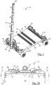
- Fig. 1 shows an exemplary embodiment of a foldable vehicle 10 according to the invention in the unfolded state.
- the vehicle 10 can be used either as a scooter to transport a person or as a handcart to transport goods.
- the vehicle 10 has a floor plate 12, a handlebar 14 and four wheels 16, 18, 20, 22.
- the base plate is divided into several plate elements 24, 26, 28, 30. In the exemplary embodiment shown there are four such plate elements. In alternative embodiments, only three such plate elements or five or more such plate elements are possible.
- Two adjacent plate elements are each connected by a hinge 32, 34, 36. In the illustrated embodiment, the plate elements 24 and 26 are connected to one another via the hinge 32, the plate elements 26 and 28 via the hinge 34 and the plate elements 28 and 30 via the hinge 36.
- the base plate 12 forms a continuous flat surface.
- the vehicle 10 can be folded into a compact state as shown in FIGS Figures 2 and 3 is shown.
- the hinges 32, 34, 36 are designed in such a way that the base plate 12 in Can be folded towards the bottom of the vehicle 10.
- the two front wheels 16, 18 are arranged on the front outer plate element 24.
- the two rear wheels 20, 22 are arranged on the rear outer plate element 30.
- the handlebar 14 is designed as a telescopic rod which has several telescopic individual elements 38, 40, 42, 44.
- Fig. 3 shows how the handlebar 14 is stowed between the plate elements 24, 26, 28, 30 in the folded state.
- Fig. 4 and Fig. 5 show the vehicle in a first state, partially unfolded around the hinge 32, how the steering rod 14 is embedded between the plate elements 24, 26, 28, 30.
- the steering rod 14 is connected to a steering axle 46, via which the wheels 16, 18 on the front plate element 24 can be steered by pivoting the steering rod 14 sideways around the steering axle 46.
- Fig.1 the handlebar 14 is shown in an upright position.
- the handlebar 14 can, however, be tilted forwards into various tilting positions and then raised back again. In each of these tilting positions, the front wheels 16, 18 can be steered by swiveling the handlebar 14 sideways. Steering is thus independent of the tilting position of the handlebar 14. This enables the vehicle 10 to be pulled by the handlebar 14 with the handlebar 14 tilted forwards and to be steered at the same time.
- the steering axle 46 is at least partially arranged in a circular opening 48 of a steering fork 50, as in Fig. 1 shown while the steering axle 46 is placed spaced from the opening 48 in the folded state of the vehicle 10, as in Fig. 4 shown.
- a lower end of the handlebar 14 has a closure 52 which can be rotatably connected to a pin 54.
- the pin 54 forms part of a steering linkage 56, which converts a lateral pivoting movement of the handlebar 14 into a steering movement of the front wheels 16, 18 in the unfolded state of the vehicle 10.
- the closure 52 can be detached from the pin 54 by pressing a movable button. Before folding the vehicle 10, this button is pressed and the connection formed by the closure 52 is released from the pin 54, so that the handlebar 14 can be decoupled from the steering linkage 56.
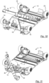
- the Figures 4 and 5 show the unfolding of the vehicle 10 around the hinge 32.
- the Figures 6 and 7 show the further unfolding of the vehicle 10 around the hinge 34.
- the Figures 7 and 8 show the further unfolding of the vehicle 10 around the hinge 36.
- Fig. 10 illustrates the lifting of the handlebar 14 and the associated pivoting of the steering fork 50 that is required to bring the handlebar 14 into its operational position.
- Fig. 11 shows the rotation of the handlebar 14 about the steering axis 46 in order to bring the closure 52 closer to the pin 54.
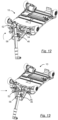
- the handlebar 14 is displaced along a retaining ring 58 connected to the steering axle 46, as shown in FIG Figures 12 and 13 shown.
- Fig. 13 finally shows that the closure 52 is attached to the pin 54 and thus the handlebar is connected to the steering linkage 56.
- FIG. 14 shows the vehicle 10 and the floor panel 12 from below Fig. 14 the vehicle 10 is in a mobile position in which the vehicle 10 stands on its wheels 16, 18, 20, 22. While according to Fig. 14 the handlebar 14 is still in the collapsed state, shows Fig. 15 the handlebar 14 in the extended state.
- Fig. 15 essentially corresponds Fig. 1.
- Fig. 1 shows an unequipped receptacle 60 at the upper end of the handlebar 14. This receptacle 60 is used to attach additional modules.
- the receptacle 60 is equipped with a control device 62 for controlling the speed of the vehicle 10.
- the receptacle 60 can be equipped with a trailer hitch, by means of which the vehicle 10 can be coupled to a bicycle, for example.
- the control device 62 can be pivoted laterally and in the Figures 2-15 shown in different pivoting positions.
- Fig. 16 shows the vehicle 10 in the unfolded state with the handlebars upright.
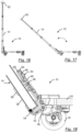
- Fig. 17 shows the vehicle 10 with the handlebar 14 tilted forward, with which the vehicle can be pulled.
- Fig. 18 shows an enlarged section of the in Fig. 17 shown area of the vehicle 10 around the front wheels, of which only the right front wheel 18 is shown to illustrate the steering mechanism in more detail.
- the handlebar 14 can be pivoted laterally about the steering axis 46 with its lowest telescopic individual element 38 by means of the retaining ring 58.
- the steering axle 46 is locked in the circular opening 48 in this state.
- the circular opening 48 is arranged in the steering fork 50.
- the steering fork 50 has a hinge 64 in the upper area, which divides the steering fork 50 in an articulated manner.
- a first part 66 of the steering fork 50 is articulated to the steering linkage 56 and the hinge 64.
- a second part 68 of the steering fork 50 is connected to the hinge 64, to the retaining ring
- the closure 52 connects in the in Fig. 18 illustrated state, the individual element 38 of the telescopic rod or handlebar 14 with the pin 54.
- the steering axis 46 is located in the circular opening 48.
- the handlebar 14 is pivoted laterally about the steering axis 46, whereby the closure 52 moves the pin 54 along the Steering linkage 56 moves so that the front wheels 16, 18 are adjusted.
- the vehicle 10 is therefore steerable.
- Fig. 19 shows an enlarged section of the in a view from above Fig. 1 vehicle shown or in Fig. 16 shown vehicle 10 without control device 62 to illustrate a locking of the steering fork 50 in the vertical state. It enables the handlebar 14, and with it the handlebar, to remain vertical, even if the user of the vehicle does not hold the handlebar 14 in position.
- the locking is preferably provided by a clamping element 70 which is arranged on the base plate 12, in particular the front plate element 24.
- This clamping element 70 preferably has a clamping lug 72 which clamps the steering fork 50 in the vertical position.
- Such a clamping element 70 is advantageously provided on each side of the steering fork 50.
- the clamping elements are preferably formed on holding edges 74, which are arranged at the front two corners of the base plate 12.
- the holding edges 74 are angled and prevent goods loaded on the base plate 12 from slipping, for example beverage crates. beyond the corners of the base plate 12.
- Fig. 19 also shows a movable button 76. By operating the button 76, the closure 52 is opened and can be separated from the pin 54. This enables easy dismantling of the handlebar 14 while folding the vehicle 10.
- Fig. 19 also shows a front light 78, with which the route can be illuminated in the dark.
- Fig. 19 Hanging straps 80 to which a strap can be mounted.
- Figures 20 to 22 show the handlebar 14 in different positions: Fig. 20 shows the handlebar 14 in a position pivoted to the left with the front wheels 16, 18 turned to the left, while Fig. 21 shows the handlebar 14 in a position pivoted to the right with the front wheels 16, 18 turned to the right.
- the handlebar 14 is in the Figures 20 and 21 only slightly tilted forward. In contrast, the handlebar 14 is in the Figures 22 and 23 tilted significantly further forward.
- the handlebar 14 is not pivoted to the left or right, so that the front wheels 16, 18 are aligned straight ahead.
- Fig. 23 the handlebar 14 is pivoted to the right, so that the front wheels 16, 18 are also pivoted to the right.
- FIGS. 20 to 23 illustrate how the closure 52 moves the steering linkage 56 laterally when the handlebar is pivoted laterally. Tilting the handlebar forward, however, does not change a steering angle of the front wheels 16, 18.
- Impact protectors 82, 84 to the right and left of the steering linkage 56 protect the steering components from damage caused by obstacles in the path, for example curbs, etc.
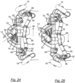
- Figures 24 and 25 show the front area of the vehicle in a view from below, where Fig. 24 the vehicle 10 with the handlebar 14 pivoted to the right and the front wheels 16, 18 turned to the right Fig. 21 shows.
- Fig. 25 shows the vehicle 10 with the handlebar 14 pivoted to the left and the front wheels 16, 18 turned to the left Fig. 20 .
- a multi-part steering mechanism 86 is connected to the pin 54 and transmits a lateral movement of the pin 54 into a pivoting movement of the wheels 16, 18.
- the steering mechanism 86 has an axially displaceable element 88 along the steering linkage 56, which is connected to a steering element 90 .
- the steering element 90 is connected via joints 92, 94 to steering arms 96, 98, by means of which the steering angle of the front wheels 16, 18 is determined.
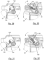
- Figures 26 to 28 show the vehicle 10 in different states: Fig. 26 shows the vehicle 10 in a not yet fully folded state, in which a brake 100 presses on the rear wheel 22 while the vehicle 10 is folded.
- the joints 28, 30 are already folded into their end position, while the joint 32 has not yet completely reached its end position.
- Fig. 27 shows how the brake 100 initially presses in the direction of the wheel 22. The spring within However, the brake 100 pushes the brake 100 back on in such a way that a contact surface 102 of the brake 100 presses against the front wheel 18 and thus keeps the vehicle in the folded state.
- Figures 29 to 32 show the brake 100 on the left rear wheel 20 in a side view from behind.
- the brake 100 is provided with a switching lever 104 which interacts with a spring 106.
- the spring 106 is arranged inside the brake 100 and presses with its first end a pressure element 108 either into a first position inside the switching lever 104, as in Fig. 30 shown when the shift lever is in its first position Fig. 29 occupies the switching position shown, or in a second position inside the switching lever 104, as in Fig. 32 shown when the shift lever is in its second position Fig. 31 occupies the switching position shown.
- the second end of the spring 106 is supported in a receptacle 110, which is arranged on the plate element 30.
- the pressure element 108 is in the first position according to Fig. 30 , the brake 100 is pushed away from the wheel 20 and is thus released. The brake 100 can nevertheless be pressed in this position by the user of the vehicle 10. In this case it serves as a service brake.
- the pressure element 108 is in the second position according to Fig. 32 , the brake 100 is pressed towards the wheel 20 and thus tightened. This tightening is done by the in Fig. 31 Shown position of the switching lever 104.
- the brake 100 serves as a parking brake in this case.
- the changeover lever 104 can therefore assume two switching positions: In the first switching position, the brake 100 serves as a service brake. Ie, the brake 100 serves to be able to brake the vehicle 10 while driving. In the second switching position, the brake 100 serves as a parking brake. Ie, the brake 100 serves in the second switching position to prevent the vehicle 10 from unintentionally rolling away when at rest. This second switching position is preferably used when parking the vehicle, especially on an inclined parking surface. If the switching lever 104 is in its first switching position, the spring 106 presses the brake 100 on if the brake 100 is not operated by foot. When the vehicle 10 is folded, the spring 106 acts as a locking mechanism that maintains the vehicle 10 in the folded state. This is exemplified in Fig. 28 shown.
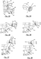
- Figures 33 to 38 show the vehicle 10 in the area of the steering fork 50 with a front light 78 arranged thereon, which is aligned by means of an alignment mechanism 112 in such a way that the front light 78 always remains aligned in the same, preferably horizontal, direction, even with different tilt angles of the steering fork 50.
- the alignment mechanism 112 makes it possible to attach the front light 78 above the base plate 12. This is advantageous because mounting the front light 78 higher offers the advantage of better illuminating the route.
- a high arrangement of the front light is only possible on a tiltable part of the vehicle 10, since all non-tiltable parts of the vehicle are arranged near the ground.
- the steering fork 50 offers an elevated position.
- the alignment mechanism 112 has an elongated flexible element 114, such as a cable, a belt, in particular a toothed belt, or a belt, which is fastened with one of its two ends to the base plate 12, in particular to the front plate element 24.
- the elongated flexible element 114 runs with a first Radius R1 about an axis of rotation of the steering linkage 56, to which the steering fork 50 is pivotally articulated.
- the front light 78 is arranged on the steering fork 50 so that it can pivot about an axis of rotation 116.
- the elongated flexible element 114 runs around the front light 78 with a second radius R2 and is attached to the front light 78 with its second end.
- the radii R1 and R2 are chosen to be the same size. As a result, the alignment of the front light 78 is maintained regardless of the tilting position of the steering fork 50.
- the steering fork 50 not shown.
- Figures 39 to 41 show the vehicle 10 initially unloaded Fig. 39 and loaded with a beverage crate 118 according to Figures 40 and 41 .
- the beverage crate rests on the base plate 12. Since the hinges 32, 34, 36 are designed such that the base plate 12 can be folded toward the underside of the vehicle 10, the load of the beverage crate 118 stabilizes the base plate 12 and secures the vehicle in its position unfolded state.
- the drinks crate is secured against slipping by means of the holding edges 74.
- the holding edges 74 are arranged at all four corners of the base plate 12 and are each angled.
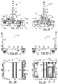
- Figures 42 to 47 show the vehicle 10 in different views: Fig. 42 shows the vehicle in a side view from behind.
- Fig. 43 shows the vehicle in a side view from the front.
- Fig. 44 shows the vehicle in a side view from the left.
- Fig. 45 shows the vehicle in a side view from the right.
- Fig. 46 shows the vehicle 10 in a view from above and Fig. 47 in a view from below. Reference is made to the above statements.
- the vehicle 10 also has a license plate holder 120 which is attached to the rear plate element 30. It is preferably also made of plastic using a 3D printing process.
- the license plate carrier 120 is flexible, so that it gives way in the event of collisions with any obstacles in the path and returns to its flat original shape after such a collision. Detailed configurations of the license plate carrier 120 are described below using Figures 53 to 56 explained.
- the vehicle 10 has a rear light 122 which is arranged on the rear plate element 30.
- the rear light 122 advantageously finds space in the circular opening 48 when the vehicle 10 is folded, as in Fig. 58 shown.
- a first receptacle 124 is provided, which optionally has a wheel suspension with a non-driven wheel Fig. 60 or an electric motor 126 with a wheel 20 driven by the electric motor 126 (as in Fig. 47 and 59 shown) can be mounted.
- a second receptacle 128 is provided, into which an accumulator 130 in the form of a rechargeable battery for supplying electrical energy to the electric motor 126 is mounted.
- a third receptacle 132 is provided, into which a control unit 134 for controlling the electric motor 126 can be mounted.
- the control unit 134, the accumulator 130 and the electric motor 126 with the wheel 20 driven by it can be removed or retrofitted.
- the vehicle 10 can therefore be provided with or without electrical components. Unless the electric motor 126 is installed with a wheel driven by it, there is a wheel suspension with a non-driven wheel 20 at this point Fig. 60 .
- Figures 48 to 52 show a section of the base plate 12 in the area of the rear plate element 30 and partly of the adjacent plate element 28 and the hinge 36, which connects these two plate elements 28, 30 to one another in an articulated manner.
- a mechanism 136 which serves to maintain the unfolded state of the vehicle 10. This mechanism 136 prevents the rear panel member 30 from inadvertently collapsing around the hinge 36, for example when the vehicle 10 rolls backwards into an obstacle.
- the mechanism 136 has a lever 138 which is pressed against the plate element 28 by a spring clip 140. The lever 138 is articulated to the rear plate member 30.
- FIGs 48, 49 and 51 show the locking state of the lever 138, in which the two plate elements 28, 30 are prevented from folding together.
- Fig. 50 shows the lever 138 in the raised position, in which the locking state is released. In this position, the hinge 36 is freely movable and the rear panel member 30 can be folded together with the panel member 28.
- Fig. 52 shows the folded state of the plate elements 28 and 30.
- the lever 138 engages on a rear edge of the base plate 28 and prevents unintentional folding.
- the lever 138 is raised.
- the lever 138 is arranged in a trough 142 provided for this purpose in the plate element 28.
- the mechanism 136 is advantageously present several times, for example twice on the right side and on the left side of the base plate 12.
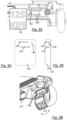
- Figures 53 to 56 show the license plate holder 120 in more detail.
- two parallel webs 144 and a further web 146 running obliquely to these webs 144 are arranged on the back of the license plate holder 120.
- the webs 144 and 146 are brought into engagement with correspondingly designed grooves, namely two parallel grooves 148 and a further groove 150 in the rear plate element 30 which runs obliquely to these grooves 148.
- the license plate holder 120 is pushed laterally into the grooves 148 by means of the webs 144 until the web 146 engages in the groove 150.
- the flexibility of the license plate holder 120 supports snapping into place.
- the license plate carrier 120 is then positively connected to the rear plate element 30.
- Fig. 56 illustrates the flexibility and flexibility of the license plate carrier 120.
- the production of the license plate carrier 120 from plastic using the 3D printing process enables a flexible license plate carrier 120, which at the same time is particularly dimensionally stable and reliably returns to its original flat shape even after being bent.
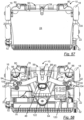
- Fig. 57 shows the vehicle 10 in the folded state according to Figures 2 and 3 , but in a view from above of the largest plate element 24 of the base plate 12.
- Fig. 58 corresponds to the illustration Fig. 57 , but without the largest plate element 24.
- Fig. 58 thus provides a view of the interior of the folded vehicle 10 and illustrates the compactness of the vehicle 10 and the location of the individual components when the vehicle 10 is in the folded state. Reference is made to the above statements.
- Fig. 59 shows the vehicle 10 with a dismantled unit 152 consisting of the electric motor 126 and a rear wheel 20 driven by the electric motor 126 after removal from the first recording 124.
- Fig. 60 shows instead of unit 152 an alternative unit 154 with a wheel suspension 156 and a non-driven wheel 20.
- the units 152 and 154 can be dismantled and reassembled by loosening screws 158. Retaining pins 160 may advantageously be provided to hold the units 152 and 154 in position during assembly and in the assembled state.
- the vehicle 10 can be upgraded with modular electrical elements such as the unit 152, the control unit 134, the control device 62 and the front light 78 and the rear light 122. At the same time, the design makes it possible to provide a basic version of the vehicle 10 without these electrical elements.
- Fig. 61 shows the vehicle 10 with mounted unit 152 and accumulator 130 above its receptacle 128 and control unit 134 mounted in receptacle 132.
- Fig. 62 shows the accumulator 130 removed from the receptacle 128, which can be removed laterally at an angle by operating a latch 162.
- guide webs 164 are provided on the accumulator 130, which interact with guide grooves 166 in the area of the receptacle 128.
- the accumulator 130 can be removed very easily in this way and, if necessary, exchanged for a freshly charged accumulator.
- Fig. 63 shows the vehicle 10 with the unit 152 dismantled, the accumulator 130 removed and the control unit 134 dismantled.
- Fig. 64 shows the above-mentioned electrical elements comprising the unit 152, the control unit 134, the control device 62 as well as the front light 78 and the rear light 122, with additional cables 168, 169 being provided for electrically connecting the electrical
- Figures 65 to 69 show the handlebar 14 in detail.
- the control device 62 is attached to the upper end of the handlebar 14 in a straight position.
- Fig. 66 shows the lateral pivotability of the control device 62, where Fig. 67 the maximum swivel position, swiveled 90° to the side, points to the left. In a corresponding manner, the control device 62 can be pivoted to the right by 90° into a maximum pivot position.
- the closure 52 at the lower end of the handlebar 14 is in the Figures 65, 68 and 69 shown.
- Fig. 68 shows the handlebar 14 with individual elements 38, 40, 42 and 44 telescopically pushed into one another.
- the individual elements 40, 42, 44 each have a sliding body 174, 176, 178, which is pressed apart by a spring 180, 182, 184.
- the sliding body 174, 176, 178 together with the associated spring 180, 182, 184 ensure that the individual elements 38, 40, 42, 44 remain in their position. That is, if the individual elements 38, 40, 42, 44 have been pulled apart, they remain pulled apart. Likewise, the individual elements 38, 40, 42, 44 remain in a nested position unless external forces are applied.
- the springs 180, 182 and 184 can be constructed identically. Due to the different diameters of the individual elements 38, 40, 42, 44, the springs 180, 182 and 184 are subjected to different preloads. The innermost individual element 44 therefore has the sliding body 178 with the greatest preload in its spring 184. In contrast, the preload of the spring 182 of the individual element 42 is less than the preload of the spring 184. The preload of the spring 180 of the individual element 40 is even lower than the preload of the spring 182 and the spring 184. The different preloads of the springs 180, 182 and 184 lead to the individual elements 38, 40 with the larger diameters being pulled apart first.
- the individual element 42 is pulled out of the individual element 40.
- the individual element 44 is pulled out of the individual element 42.
- This order is determined by the different preloads of the springs 180, 182 and 184.
- This design is advantageous because it ensures that the individual elements with a larger diameter are primarily effective and are more stable than the individual elements with a smaller diameter. When pushing together, the individual elements with the largest diameters are pushed together first. This can be used advantageously to allow the individual elements with a smaller diameter to take effect if necessary.
- Fig. 70 illustrates the vehicle 10 in a folded state, with the control device 62 at the upper end of the handlebar 14 being folded laterally.
- Figures 71 and 72 show the front steerable wheel 16 in a sectional view.
- An axis of rotation 186 of the wheel 16 is rotatably mounted in a bearing part 188 about an axis of rotation 190 which is arranged in the plate element 24.
- a bearing chamber 192 in the plate element 24 accommodates two ball bearings 194, 196, each with an inner and outer bearing ring.
- the two inner bearing rings are connected to an inner spacer sleeve 198 and the two outer bearing rings are connected to an outer spacer sleeve 200, so that the weight of the vehicle 10, possibly including the load, can be evenly distributed between both ball bearings 194, 196.
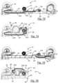
- Figures 73 and 74 show a cable duct 202 which runs through the plate elements 24, 26 and 28 and the hinges 32 and 34 and leads a cable 204 from the control unit 134 to the front light 78.
- Figures 75 and 76 show a further cable duct 206, which runs through the plate elements 28 and 30 and the hinge 36 and leads a cable 208 from the control unit 134 to the rear light 122.
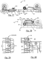
- Figures 77 and 78 show the one in the Figures 75 and 76 another cable duct 206 shown in the opposite direction.
- Fig. 79 shows a section along one of the hinges 32, 34, 36 between two plate elements 24, 26, 28, 30 with a cable bushing 210 through the hinge 32, 34, 36 in a view from below onto the base plate 12.
- Fig. 80 shows such a section by way of example on the hinge 34 between the plate elements 26 and 28.
- Such a hinge 32, 34, 36 consists of a first hinge part 212 on one of the two plate elements adjacent to the hinge, for example on the plate element 26, and of a second hinge part 214 on the other plate element adjacent to the hinge, for example on the plate element 28.
- Each of the hinge parts consists of a series of cantilever webs.
- the first hinge part 212 has a series of cantilever webs 216 lying parallel to one another and the second hinge part 214 has a series of cantilever webs 218 lying parallel to one another.
- a cantilever web 218 is replaced on one of the two hinge parts 214 by a hole which leads into the interior of the adjacent plate element 28.
- a gap cover 220 is provided on the other of the two hinge parts 212. It contributes to the cable (in Fig. 79 and 80 not shown).
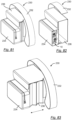
- Figures 81 to 83 show a fold-out bag 230 with a carrying strap 232, which is used to hang the bag 230 around.
- the bag 230 includes a side pocket 234 for receiving the vehicle 10 when folded, as shown in Fig. 82 shown.
- the dimensions of the side pocket 234 are adapted to the dimensions of the vehicle 10 in the folded state.
- the bag 230 also includes a main bag 236 for holding all kinds of goods, for example purchased goods.
- the main pocket 236 is preferably foldable in order to be able to vary its volume.
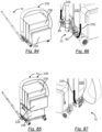
- Fig. 84 shows the bag 230 in the unfolded state of the main bag 236.
- the bottom surface of the main bag 236 in the unfolded state is adapted to the surface of the base plate 12 of the vehicle 10, so that the bag 230 can be placed safely on the base plate 12. Due to the adaptation of the bottom surface of the main pocket 236 to the surface of the base plate 12, the pocket 230 is securely held by the holding edges 74 at the corners of the base plate 12. This prevents the pocket 230 from slipping or sliding away over the edges of the base plate 12.
- the side pocket 234 is designed such that it protrudes beyond the surface of the base plate 12. This makes it possible to provide a larger volume of the bag 230.
- the bottom area of the main pocket 236 is adapted to the bottom area of a commercially available beverage crate 238, as in Fig. 85 shown.
- Figures 86 and 87 show pocket straps 239 mounted on the hanging tabs 80. These pocket straps 239 are sewn to the pocket 230 or firmly connected in another way, for example by welding or gluing.
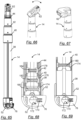
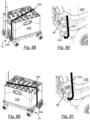
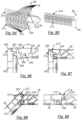
- Figures 88 to 93 show a strap 240 with variable length, which can be used either as a shoulder strap for carrying the vehicle 10 in the folded state or as a tension strap for fixing loads on the floor panel 12 of the vehicle 10 in the unfolded state.
- the Figures 86 to 92 show the use of the strap 240 as a tension strap to secure loads. In detail they show Figures 86 and 87 the fixation of the bag 230 using the strap 239.
- the Figures 88 to 92 show the fixation of a drinks crate 238 using the strap 240.
- Fig. 93 shows the attachment of the strap 240 in the hanging straps 80 for using the strap 240 as a carrying strap.
- one end piece 242, 244 of the belt 240 is fastened into a hanging tab 80 on the front plate element 24 and a hanging tab 246 in the area of the rear plate element 30, for example in the area of the rear light 122.
- FIGS 94 to 99 show a hinge, for example the hinge 34, in more detail.
- the hinges 32 and 36 are advantageously designed analogously.
- the hinge 34 includes the first hinge part 212 and the second hinge part 214.
- the first hinge part 212 has a series of first cantilever webs 216 arranged parallel to one another.
- the second hinge part 214 has a series of second cantilever webs 218 arranged parallel to one another.
- a gap is formed between two adjacent cantilever webs 216 or 218 of a hinge part 212, 214, into which a cantilever web 218 or 216 of the other hinge part 214, 212 engages.
- the hinge parts 212, 214 are designed in such a way that they can be plugged together and still hold together reliably when the vehicle 10 is in the unfolded state but also in the folded state.
- Each of the cantilever webs 216, 218 decreases in height toward its end portion.
- the height of each of the cantilever webs 216, 218 in the end section is only approximately half as large as in the main section adjacent to the end section.
- These end sections each have a downward, preferably horizontal, support surface 222 when the vehicle 10 is in the unfolded and operational state.
- Each of the spaces between two adjacent cantilever webs 216 and 218 has a step 224 in an initial section.
- the height of the step 224 is in turn only half the height of the cantilever webs 216 and 218.
- the downward-facing support surfaces 222 of the end sections of the cantilever webs 216, 218 lie on the upward-facing support surfaces of the steps 224.
- rotation axis bearings 250 are provided, while in the cantilever webs 218 of the other hinge part, for example the second hinge part 214, rotation axes 252 are provided.
- the rotation axes 252 of one hinge part 214 are supported in the rotation axis bearings 250 of the other hinge part 212.
- the cantilever webs 216, 218 are designed in length, width and with roundings 254, 256, 258, 260 such that a human finger cannot be caught between the cantilever webs 216, 218.
- each of the cantilever webs 216, 218 has an upwardly directed rounding 254, 256 at its end section and a downwardly directed rounding 258, 260 at the main section adjacent to this end section.
- the invention provides a versatile vehicle that can be used, in particular, for shopping for larger purchases, without the user needing a conventional car.
- the user can either drive to his shopping location or carry the vehicle there - either in a bag or hanging on a belt - or pull it behind him like a handcart.
- the purchased goods including beverage crates, can be loaded onto the vehicle and the vehicle can be towed or driven home.
- the vehicle Due to its design, the vehicle can be folded up into a small pack size. Because it is made from plastic using a 3D printing process, the vehicle is light and therefore transportable. The vehicle is therefore particularly suitable in residential areas where conventional cars are not desired or permitted, but also for environmentally conscious people.
Landscapes
- Engineering & Computer Science (AREA)
- Mechanical Engineering (AREA)
- Chemical & Material Sciences (AREA)
- Combustion & Propulsion (AREA)
- Transportation (AREA)
- Handcart (AREA)
Applications Claiming Priority (1)
| Application Number | Priority Date | Filing Date | Title |
|---|---|---|---|
| DE102022124205.6A DE102022124205B3 (de) | 2022-09-21 | 2022-09-21 | Zusammenfaltbares Fahrzeug sowie System aus einem derartigen Fahrzeug und einer Tasche |
Publications (1)
| Publication Number | Publication Date |
|---|---|
| EP4342768A1 true EP4342768A1 (fr) | 2024-03-27 |
Family
ID=87762432
Family Applications (1)
| Application Number | Title | Priority Date | Filing Date |
|---|---|---|---|
| EP23193012.4A Pending EP4342768A1 (fr) | 2022-09-21 | 2023-08-23 | Véhicule pliable et système comprenant un tel véhicule et une poche |
Country Status (2)
| Country | Link |
|---|---|
| EP (1) | EP4342768A1 (fr) |
| DE (1) | DE102022124205B3 (fr) |
Families Citing this family (1)
| Publication number | Priority date | Publication date | Assignee | Title |
|---|---|---|---|---|
| CN222474346U (zh) * | 2024-01-16 | 2025-02-14 | 士商(上海)机械有限公司 | 一种折叠便捷的代步车 |
Citations (8)
| Publication number | Priority date | Publication date | Assignee | Title |
|---|---|---|---|---|
| US20060220334A1 (en) | 2005-03-29 | 2006-10-05 | Liao Li W | Article carrying cart |
| CN201492901U (zh) | 2009-08-13 | 2010-06-02 | 戚利聪 | 一种可折叠滑板 |
| CN202029972U (zh) | 2011-03-11 | 2011-11-09 | 郑炳辉 | 行李自行车结构 |
| WO2017189861A1 (fr) * | 2016-04-29 | 2017-11-02 | Out Of The Box Concepts, Llc | Chariot pliant |
| CN107878651A (zh) | 2017-12-10 | 2018-04-06 | 宁波市镇海丹发机械科技有限公司 | 折叠式六轮电动多用车 |
| CN108639115A (zh) * | 2018-03-30 | 2018-10-12 | 广州大学 | 一种多功能手推车 |
| US20190127010A1 (en) | 2015-12-16 | 2019-05-02 | South China University Of Technology | Portable electric vehicle and method for controlling drive thereof |
| DE202020104896U1 (de) * | 2020-08-25 | 2020-09-16 | Lenzio Sas | Transportvorrichtung |
-
2022
- 2022-09-21 DE DE102022124205.6A patent/DE102022124205B3/de active Active
-
2023
- 2023-08-23 EP EP23193012.4A patent/EP4342768A1/fr active Pending
Patent Citations (8)
| Publication number | Priority date | Publication date | Assignee | Title |
|---|---|---|---|---|
| US20060220334A1 (en) | 2005-03-29 | 2006-10-05 | Liao Li W | Article carrying cart |
| CN201492901U (zh) | 2009-08-13 | 2010-06-02 | 戚利聪 | 一种可折叠滑板 |
| CN202029972U (zh) | 2011-03-11 | 2011-11-09 | 郑炳辉 | 行李自行车结构 |
| US20190127010A1 (en) | 2015-12-16 | 2019-05-02 | South China University Of Technology | Portable electric vehicle and method for controlling drive thereof |
| WO2017189861A1 (fr) * | 2016-04-29 | 2017-11-02 | Out Of The Box Concepts, Llc | Chariot pliant |
| CN107878651A (zh) | 2017-12-10 | 2018-04-06 | 宁波市镇海丹发机械科技有限公司 | 折叠式六轮电动多用车 |
| CN108639115A (zh) * | 2018-03-30 | 2018-10-12 | 广州大学 | 一种多功能手推车 |
| DE202020104896U1 (de) * | 2020-08-25 | 2020-09-16 | Lenzio Sas | Transportvorrichtung |
Also Published As
| Publication number | Publication date |
|---|---|
| DE102022124205B3 (de) | 2023-12-07 |
Similar Documents
| Publication | Publication Date | Title |
|---|---|---|
| DE69119237T2 (de) | Kraftfahrzeug | |
| EP3488839B1 (fr) | Déambulateur à entraînement électrique | |
| DE102017114585B4 (de) | Motorisierte Transportkarre | |
| EP1267657B1 (fr) | Bagage a roulettes | |
| EP1003663B1 (fr) | Chariot de transport deplacable manuellement | |
| EP3145800B1 (fr) | Trottinette à voie unique | |
| WO2019101635A1 (fr) | Déambulateur à roulettes, à entraînement électrique | |
| DE19534974A1 (de) | Zusammenlegbare Karre | |
| DE3112768A1 (de) | Klappbares fahrrad | |
| DE102022124205B3 (de) | Zusammenfaltbares Fahrzeug sowie System aus einem derartigen Fahrzeug und einer Tasche | |
| DE102018115003B4 (de) | Ständerbaugruppe und ein fahrrad, welches die ständerbaugruppe verwendet | |
| DE102018205864A1 (de) | Roller mit einem Trittbrett und Verfahren zum Bedienen eines Rollers | |
| EP4263335A2 (fr) | Trottinette pliable, et ensemble de multiples modules de batterie rechargeable | |
| DE102018110024A1 (de) | Zusammenlegbare Rollkarre für den Transport gestapelter Güter | |
| EP1448073A1 (fr) | Dispositif de transport pour bagages ou analogues | |
| DE102022201256B3 (de) | Elektrisch antreibbarer Lastenroller | |
| DE202019002514U1 (de) | Mehrspuriges Gefährt zur Beförderung von Lasten | |
| DE202012007192U1 (de) | Nutzfahrzeug | |
| WO1998056640A1 (fr) | Skibob | |
| DE69401597T2 (de) | Verbesserter Wagen für handgetragene Gegenstände wie Koffer oder ähnliches | |
| EP0726194B1 (fr) | Remorque de véhicule | |
| DE102020117679A1 (de) | Fahrradanhänger mit verschwenkbarer Deichsel | |
| DE102021125388B4 (de) | Klappbares Fahrrad | |
| DE102020101377A1 (de) | Roller zum bedarfsweisen Mitführen von Rollgut | |
| DE112020002599B4 (de) | Mehrspuriges Gefährt zur Beförderung von Lasten |
Legal Events
| Date | Code | Title | Description |
|---|---|---|---|
| PUAI | Public reference made under article 153(3) epc to a published international application that has entered the european phase |
Free format text: ORIGINAL CODE: 0009012 |
|
| STAA | Information on the status of an ep patent application or granted ep patent |
Free format text: STATUS: THE APPLICATION HAS BEEN PUBLISHED |
|
| AK | Designated contracting states |
Kind code of ref document: A1 Designated state(s): AL AT BE BG CH CY CZ DE DK EE ES FI FR GB GR HR HU IE IS IT LI LT LU LV MC ME MK MT NL NO PL PT RO RS SE SI SK SM TR |
|
| RAP3 | Party data changed (applicant data changed or rights of an application transferred) |
Owner name: KATAPULT INNOVATION GMBH |
|
| STAA | Information on the status of an ep patent application or granted ep patent |
Free format text: STATUS: REQUEST FOR EXAMINATION WAS MADE |
|
| 17P | Request for examination filed |
Effective date: 20240924 |
|
| RBV | Designated contracting states (corrected) |
Designated state(s): AL AT BE BG CH CY CZ DE DK EE ES FI FR GB GR HR HU IE IS IT LI LT LU LV MC ME MK MT NL NO PL PT RO RS SE SI SK SM TR |
|
| RIC1 | Information provided on ipc code assigned before grant |
Ipc: B62B 3/02 20060101AFI20250924BHEP Ipc: B62J 6/025 20200101ALI20250924BHEP Ipc: B62J 7/08 20060101ALI20250924BHEP Ipc: B62J 9/20 20200101ALI20250924BHEP Ipc: B62J 11/19 20200101ALI20250924BHEP Ipc: B62J 19/00 20060101ALI20250924BHEP Ipc: B62J 25/04 20200101ALI20250924BHEP Ipc: B62J 27/30 20200101ALI20250924BHEP Ipc: B62J 43/16 20200101ALI20250924BHEP Ipc: B62J 43/20 20200101ALI20250924BHEP Ipc: B62J 45/20 20200101ALI20250924BHEP Ipc: B62J 50/26 20200101ALI20250924BHEP Ipc: B62K 5/00 20130101ALI20250924BHEP Ipc: B62K 5/01 20130101ALI20250924BHEP Ipc: B62K 5/08 20060101ALI20250924BHEP Ipc: B62K 19/30 20060101ALI20250924BHEP Ipc: B62K 21/22 20060101ALI20250924BHEP Ipc: B62L 1/04 20060101ALI20250924BHEP Ipc: B62L 3/04 20060101ALI20250924BHEP |
|
| GRAP | Despatch of communication of intention to grant a patent |
Free format text: ORIGINAL CODE: EPIDOSNIGR1 |
|
| STAA | Information on the status of an ep patent application or granted ep patent |
Free format text: STATUS: GRANT OF PATENT IS INTENDED |
|
| INTG | Intention to grant announced |
Effective date: 20251119 |
|
| GRAS | Grant fee paid |
Free format text: ORIGINAL CODE: EPIDOSNIGR3 |
|
| GRAJ | Information related to disapproval of communication of intention to grant by the applicant or resumption of examination proceedings by the epo deleted |
Free format text: ORIGINAL CODE: EPIDOSDIGR1 |
|
| GRAL | Information related to payment of fee for publishing/printing deleted |
Free format text: ORIGINAL CODE: EPIDOSDIGR3 |
|
| STAA | Information on the status of an ep patent application or granted ep patent |
Free format text: STATUS: REQUEST FOR EXAMINATION WAS MADE |
|
| GRAP | Despatch of communication of intention to grant a patent |
Free format text: ORIGINAL CODE: EPIDOSNIGR1 |
|
| STAA | Information on the status of an ep patent application or granted ep patent |
Free format text: STATUS: GRANT OF PATENT IS INTENDED |
|
| INTC | Intention to grant announced (deleted) |