EP4342795A2 - Dispositif de verrouillage et pont de chargement - Google Patents
Dispositif de verrouillage et pont de chargement Download PDFInfo
- Publication number
- EP4342795A2 EP4342795A2 EP23220738.1A EP23220738A EP4342795A2 EP 4342795 A2 EP4342795 A2 EP 4342795A2 EP 23220738 A EP23220738 A EP 23220738A EP 4342795 A2 EP4342795 A2 EP 4342795A2
- Authority
- EP
- European Patent Office
- Prior art keywords
- locking device
- fastening
- guide rails
- carriage
- longitudinal beams
- Prior art date
- Legal status (The legal status is an assumption and is not a legal conclusion. Google has not performed a legal analysis and makes no representation as to the accuracy of the status listed.)
- Granted
Links
Images


Classifications
-
- B—PERFORMING OPERATIONS; TRANSPORTING
- B64—AIRCRAFT; AVIATION; COSMONAUTICS
- B64D—EQUIPMENT FOR FITTING IN OR TO AIRCRAFT; FLIGHT SUITS; PARACHUTES; ARRANGEMENT OR MOUNTING OF POWER PLANTS OR PROPULSION TRANSMISSIONS IN AIRCRAFT
- B64D9/00—Equipment for handling freight; Equipment for facilitating passenger embarkation or the like
- B64D9/003—Devices for retaining pallets or freight containers
-
- B—PERFORMING OPERATIONS; TRANSPORTING
- B64—AIRCRAFT; AVIATION; COSMONAUTICS
- B64C—AEROPLANES; HELICOPTERS
- B64C1/00—Fuselages; Constructional features common to fuselages, wings, stabilising surfaces or the like
- B64C1/18—Floors
- B64C1/20—Floors specially adapted for freight
-
- B—PERFORMING OPERATIONS; TRANSPORTING
- B64—AIRCRAFT; AVIATION; COSMONAUTICS
- B64D—EQUIPMENT FOR FITTING IN OR TO AIRCRAFT; FLIGHT SUITS; PARACHUTES; ARRANGEMENT OR MOUNTING OF POWER PLANTS OR PROPULSION TRANSMISSIONS IN AIRCRAFT
- B64D9/00—Equipment for handling freight; Equipment for facilitating passenger embarkation or the like
- B64D2009/006—Rollers or drives for pallets of freight containers, e.g. PDU
Definitions
- the invention relates to a locking device for securing items of cargo on a cargo deck of an aircraft.
- the invention further relates to a cargo deck of an aircraft with at least one locking device.
- cargo items e.g. B. containers or pallets (“unit load devices - ULDs") are used that are cuboid or trapezoidal or have a shape with a special outer contour.
- containers or pallets can be loaded lengthways or sideways depending on the cargo space of the aircraft. It is therefore necessary to adapt locking elements in terms of their position in the cargo hold floor.
- locking units must therefore be laterally adjustable in order to be able to lock asymmetrical loading configurations or different ULD widths.
- Containers or similar cargo to be secured on the cargo floor of an aircraft can be of different sizes.
- Locking elements with latches are used to secure containers.
- the bars encompass and hold a section of the container or a freight pallet. To do this, the distances between the bars must be maintained of a piece of freight correspond to the size of the respective piece of freight. If the spacing of the latches does not correspond to the sizes of the freight items, these freight items cannot be reliably secured by the latches.
- locking units must be able to be driven over by wider ULDs in the case of single-lane loading. Users want the corresponding locking elements to fold down automatically when they are driven over, so that easy loading is possible even when wider ULDs are present.
- locking elements be installed in the area of side cargo doors on the cargo deck of an aircraft when entering and exiting Unloading ULDs can be moved to the side and folded down. This is intended to enable lateral transfer through a cargo door without ULDs colliding with the locking elements.
- the locking device should ensure adequate securing of cargo items in the so-called “wing opening” load case.
- the locking device should be designed in such a way that it can be folded down automatically when driving over fastening claws. A simple determination as to whether the fastening claw is locked in a folded state is also desirable.
- the locking device thus has at least one fastening claw which has a toggle lever mechanism.
- Designing the toggle lever mechanism has the advantage that the fastening claw can be automatically locked when pressed downwards.
- the toggle lever mechanism is designed such that the fastening claw is automatically locked in a folded down position. The fastening claw can be swung out again by lightly pressing a release device.
- the fastening claw is pivotably attached to the slide element by means of the toggle lever mechanism.
- the toggle lever mechanism has at least two lever elements that are articulated to one another.
- the toggle lever mechanism preferably has a triggering device, in particular a triggering button or a triggering pin, wherein the triggering device, when actuated, releases the toggle lever mechanism from a locked, folded-down position of the fastening claw.
- the triggering device is preferably designed as a section of at least one lever element of the toggle lever mechanism. Due to the actuation of the triggering device, the further lever element, in particular the lever element that is connected to the fastening claw or is located in the fastening claw, is released from a maximum locking position.
- the folded position of the fastening claw affects the position of the fastening claw in which the fastening claw no longer protrudes vertically over the guide rails.
- the folded position causes the fastening claw and the locking lug on it to sink below the uppermost side edge of the longitudinal beams. It is therefore possible for cargo items, in particular ULDs, to be transported via the locking device in this folded down position of the fastening claw.
- the pressure on the triggering device can be done, for example, by actuating it with your foot. With the help of the toggle mechanism, both locking and unlocking can be done with one foot. This meets the convenience of use.
- the fastening claw can be locked in the folded down position. Due to the support of the toggle lever on a slide element, this concept of the toggle lever mechanism can also be used for locking devices that are based on the concept of two separate, individually movable fastening claws.
- the toggle lever mechanism is protected in the fastening claw. On the one hand, this reduces the risk of damage to the mechanism.
- the mechanism can be effectively protected from dirt and moisture.
- the toggle lever mechanism can be adjusted in such a way that the fastening claw is folded down when a piece of freight, in particular a ULD, is driven over and is automatically locked in this folded down position.
- guide rails that are attached to the longitudinal beam, with at least two carriage elements being slidably mounted in the guide rails, enables improved force transmission between the fastening claws and the longitudinal beams. This enables the fastening claws and the longitudinal beams to be made of aluminum, even with high transmitted forces. This leads to significant weight savings since no elements need to be made of steel.
- the inventive design of guide rails and the carriage element mounted therein enables better guidance or displaceability of the fastening claw. Furthermore, such an arrangement is less sensitive to dirt and protects against corresponding damage to the locking device.
- This embodiment assumes a locking device that has at least two fastening claws with locking lugs on them.
- the fastening claws can be moved and fixed in the frame in such a way that the position of the fastening claws and the locking lugs located thereon in the cargo deck of an aircraft can be adjusted.
- the distance between the fastening claws for securing a container can therefore be adapted to different sizes of containers, in particular ULDs.
- the frame preferably comprises at least two longitudinal beams and preferably at least two end crossbars.
- the frame preferably comprises four side elements, which are formed from two longitudinal beams and two traverses.
- the fastening claws are each movably mounted separately on slide elements, the fastening claws can carry out pivoting movements that are independent of one another.
- the actual locking or fastening of the cargo items is carried out using the locking lugs located on the fastening claws.
- the distance between the fastening claws is variable.
- the distance can be adapted to specific loading situations by forming at least one compression spring between the carriage elements, so that the two carriage elements are mounted in a spring-loaded manner against one another.
- the locking lugs can further ensure the fastening of the cargo items by moving the carriage elements away from each other.
- the respective fastening claws can follow the secured pallet or container, so that vertical locking of the load of the respective cargo items is guaranteed for both fastening claws.
- the carriage elements can be moved towards each other again due to the compression spring formed between the carriage elements.
- the distance between the carriage elements is reduced so that the fastening claws with the locking lugs on them can continue to secure the cargo items in a vertical direction.
- the carriage elements are slidably mounted on the guide rails.
- the carriage elements preferably have sliding elements on two sides, so that the carriage elements themselves are slidably mounted on the guide rails. Due to the free movement of the carriage elements in the guide rails, lateral suspension can be made possible.
- the carriage elements are not directly connected to the at least two longitudinal beams or are not mounted directly on the longitudinal beams.
- the at least two guide rails form a type of intermediate carriage element, so that lateral suspension is positively influenced.
- the fastening claws in the carriage elements are preferably arranged in such a way that the fastening claws can be folded down (in opposite pivoting directions).
- a guide rail as a type of intermediate element for supporting the fastening claws on the longitudinal beams of a frame, it is possible for the fastening claws to be displaceable in pairs along the longitudinal beams.
- the guide rails are preferably releasably fastened in or on the longitudinal beams.
- the Guide rails are detachably fastened in groove-shaped recesses in the longitudinal beams.
- the guide rails are releasably attached in such a way that the guide rails can be arranged variably with regard to their respective position in relation to the respective longitudinal beam.
- the guide rails are preferably designed to be congruent with one another. In other words, no lateral offset should be formed between the guide rails. Rather, the guide rails should be movable in the same direction in the longitudinal beams.
- a variable arrangement of the guide rails in or on the longitudinal beams is preferably possible through different openings that are formed in the longitudinal beams. These openings in the side members allow different positions with regard to the fastening claws in relation to the side members or to the entire frame due to different distances between the openings and the number of openings.
- the guide rails can be connected to each other.
- the guide rails can be connected to one another, for example, by means of traverses and/or connecting webs. It is also possible for the guide rails to be connected to one another using a single connecting web.
- the connecting web is formed centrally with respect to both guide rails with respect to their longitudinal extent. In a top view, the guide rails form an H-shape with the central connecting bar.
- Guide rails connected to one another can form a carriage or a frame.
- the at least two guide rails, the at least two fastening claws and the at least two carriage elements form an assembly, this assembly being variably positionable and attachable in relation to the longitudinal beams.
- the assembly can be completely moved in relation to the longitudinal beams or the entire frame. This allows the mounting claws to be positioned off-center. This allows an asymmetrical ULD configuration to be loaded and attached.
- At least two spring units are formed between the carriage elements, with one spring unit having at least one compression spring.
- at least two compression springs can be formed between the carriage elements.
- the spring units are preferably located at different locations between the at least two carriage elements.
- the arrangement is symmetrical in relation to a longitudinal axis of the locking device formed between the two guide rails. This ensures that the two spring units are subjected to a correspondingly even load.
- the at least one compression spring preferably the at least two spring units
- the at least one compression spring or the at least two spring units are moved accordingly when the above-mentioned assembly moves. There is therefore no need to form separate spring units for different positioning of the fastening claws. This simplifies the structure of the locking device and minimizes the number of spring units required.
- At least one fastening claw can be mounted on a slide element so that it can rotate about an axis of rotation that runs essentially perpendicular to the guide rails. If the axis of rotation is designed to run essentially perpendicular to the guide rails, a necessarily mathematically correct vertical design is not to be understood. Rather, this is intended to indicate the essential tendency of the alignment of the axis of rotation.
- the two longitudinal beams of the frame can also be referred to as bending beams, in particular as lateral bending beams.
- the longitudinal beams serve to absorb the forces acting on the fastening claws.
- the guide rails cause high tensile and twisting forces, which act on the fastening claws, to be transferred to the two longitudinal beams. Since the carriage elements are not directly connected to the longitudinal beams, for example by means of axle stubs, much higher tensile and twisting forces can be absorbed due to the guide rails designed.
- the frame of the locking device preferably comprises fastening means with which the frame can be fastened to a cargo hold floor of an aircraft.
- At least one of the guide rails can be designed as a C-profile rail. This enables the carriage elements to be mounted in such a sliding manner in the guide rail that sliding elements of the carriage elements are prevented from slipping out laterally from the guide rail.
- At least one guide rail can be releasably attached to at least one of the longitudinal beams by means of a, in particular prestressed, fastening pin, the fastening pin engaging in an opening in the guide rail.
- the fastening pin comprises a spring.
- the fastening pin can be mounted so as to be displaceable against a spring force in order to release an existing connection with the guide rail. This has the advantage that the fastening pin can be easily released. Another advantage is that a fastening pin can be positioned at defined positions, i.e. H. in the vicinity of an opening in the guide rail through which the spring force can simply snap into place.
- the fastening pin can be locked and/or released by means of a link guide device.
- At least one stop element for at least one carriage element can be formed in the guide rail.
- the carriage element can be freely movable in the guide rail over a defined distance. With the help of the stop element, when the carriage element is in contact with the stop element, the force is transmitted from the carriage element via the stop element into the guide rail and from the guide rail into the longitudinal beam.
- the at least one stop element in the guide rail is designed as a stop element for at least two carriage elements.
- the stop element is preferably designed as a projection in the guide rail.
- the stop element is preferably formed at a central position in the lateral extent.
- a carriage element has stop surfaces and/or stop edges which limit a pivoting movement of the fastening claw.
- the radius of movement of the fastening claw can be defined with the help of stop surfaces and/or stop edges of the slide element. This affects both the movement of the fastening claw to assume a folded position and the range of motion of the fastening claw to assume an unfolded position.
- One aspect of the invention relates to a cargo deck of an aircraft with at least one locking device according to the invention.
- the frame of the locking device is attached to the floor of the cargo deck.
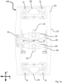
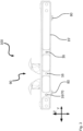
- FIG. 1a is a top view ( Fig. 1a ) and a perspective side view ( Fig. 1b ) of a possible embodiment with regard to a locking device 100 is shown.
- the locking device 100 has a frame 10.
- the frame 10 has two longitudinal beams 15, 15 'and traverses 18, 18'.
- the frame 10 is formed by the four side elements, namely the two longitudinal beams 15, 15 'and the two traverses 18, 18'.
- Rollers 11 are formed in the traverses 18, 18 '. These rollers 11 are used to transport items of freight, in particular ULDs, over the locking device 100.
- the fastening claws 20, 20 ' each have a locking lug 25, 25'.
- the fastening claws 20, 20' are each movably mounted on a slide element 30, 30'.
- the locking device 100 further comprises two guide rails 40, 40'.
- the left guide rail 40 can be seen at least in sections.
- the guide rails 40, 40' can be attached to the longitudinal beams 15, 15' at different positions.
- the longitudinal beams 15, 15 ' have openings 16 (see Fig. 1b , right side).
- the guide rails 40, 40' can be fastened at different positions of the longitudinal beams 15, 15'.
- the carriage elements 30, 30' are slidably mounted on the guide rails 40, 40'.
- compression springs 50 are formed between the carriage elements 30, 30 '.
- the carriage elements 30, 30' With the help of the illustrated construction of a locking device 100, it is possible for the carriage elements 30, 30' to be slidably mounted in the guide rails 40, 40', with the guide rails 40, 40' in turn being attachable to different positions of the longitudinal beams 15, 15' are. Since the carriage elements 30, 30' are not mounted directly on the longitudinal beams 15, 15', but rather the guide rails 40, 40' are designed as a type of intermediate carriage, lateral suspension is made possible. The carriage elements 30, 30' can be moved in pairs along the y-axis together with the fastening claws 20, 20'.
- compression springs 50 are formed between carriage elements 30 and 30 'on which the fastening claws 20, 20' are movably mounted, these compression springs 50 are used together with the other components, i.e. H. moved together with the guide rail 40, 40 ', the carriage elements 30, 30' and with the fastening claws 20, 20'.
- the two carriage elements 30, 30 ' are displaceable relative to one another and are spring-mounted.
- the two fastening claws 20, 20 ' can follow the respective containers or ULDs, so that vertical locking of the load is also ensured in this case.
- the guide rails 40, 40' are releasably attached to the longitudinal beams in groove-shaped recesses 19 in the longitudinal beams 15, 15'.
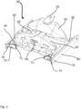
- Fig. 4 the assembly 90 is shown detached from the frame 10 or the longitudinal beams 15, 15 '. It can be seen that the assembly 90 is formed by the two guide rails 40, 40', the fastening claws 20, 20', the carriage elements 30, 30' and the compression springs (not visible here). This entire assembly 90 is slidably mounted in the groove-shaped recesses 19 of the longitudinal beams 15, 15 '.
- Fig. 4 It can be seen that the assembly 90 can be attached to the longitudinal beams 15, 15 'by means of a prestressed fastening pin 70.
- the fastening pin 70 engages in one of the openings 16 of the longitudinal beams 15, 15 '(see Fig. 1b ) a.
- a link guide device 72 can be operated using a lever. With the help of this link guide device 72, the fastening pin 40 can be locked and released. Due to the pretension of the fastening pin 70, which is realized by means of a spring (not shown), the fastening pin 70 can slide independently into an opening 16, provided that the fastening pin 70 is in direct proximity to the opening 16 and already partially engages in it. The device is then closed manually using the lever 72.
- a stop element (not shown) can also be formed in the guide rails 40, 40 'at a central position with respect to the longitudinal extent. The carriage elements 30, 30' can abut centrally on this stop element, so that the minimum distance between the carriage elements 30, 30' can be adjusted with the aid of a stop element.
- the fastening claws 20, 20' In order to enable containers/ULDs to be transported over the locking device 100, the fastening claws 20, 20' must be designed to be foldable. Furthermore, it is provided that the locking lugs 25, 25' can be folded away laterally. The fastening lugs 25 and 25' are thus laterally movable in the direction of the x-axis.
- Fig. 2a the unfolded state of the fastening claws 20, 20 'is shown.
- the compression spring 50 can also be seen, which resiliently distances the two carriage elements 30, 30 'from one another.
- one of the fastening claws 20, 20' is to be folded down, it can be folded downwards by applying appropriate force to the surface 28, 28' of the fastening claw 20, 20'.
- the fastening claws 20, 20 ' are rotatably mounted in relation to the carriage element 30, 30 '. The axis of rotation 35, 35 'can be seen accordingly.
- This toggle lever mechanism 60 has a first lever element 61 and a second lever element 62.
- the first lever element 61 is attached to the fastening claw 20, 20'.
- the second lever element 62 is attached to the slide element 30, 30 '.
- Fig. 2b the fastening claws 20, 20' are each shown in the folded down and locked state.
- the fastening claws 20, 20' are folded down in such a way that they no longer protrude beyond the longitudinal beam 15, 15'.
- the surface 28, 28' of the fastening claw 20, 20' is rotated in such a way that it is now aligned with the uppermost side edge 12 of the longitudinal beam 15, 15'. Any freight items and ULDs can be transported over the locking device 100 with the help of the rollers 11 in this state of the fastening claws 20, 20 '.
- the toggle lever mechanism 60, 60 ' is in the in Fig. 2b Position shown is designed such that a portion of the second lever element 62 points upwards. This section serves as a triggering device 65.
- the toggle lever mechanism 60, 60 ' is triggered by slight pressure, which can be applied, for example, due to the actuation by means of a foot, so that the fastening claws 20, 20' can be folded up again, so that they according to their original position Fig. 2a can take.
- Stop surfaces 34, 34' and 36, 36' are formed on the carriage elements 30, 30', which limit the pivoting movements of the fastening claws 20, 20'.
- Fig. 3 an alternative positioning of the assembly 90 is indicated. It can be seen that the fastening claws 20, 20 'in the example shown point downwards (in relation to Fig. 1a ) or shifted to the left. The fastening claws 20, 20' are arranged together with the locking lugs 25, 25' in an unfolded position. In the present case, the assembly 90 is fastened by means of a fastening pin 70 to the opening 16, which is formed on the far left of the longitudinal beam 15 '.
- the locking device 100 has fastening means 80, with the help of which the locking device 100 can be fastened to the floor of a cargo deck.
- Locking device (100) according to exemplary embodiment 1, characterized in that the guide rails (40, 40') are releasably fastened in or on the longitudinal beams (15, 15'), preferably in groove-shaped recesses (19) of the longitudinal beams (15, 15'). are, such that the guide rails (40, 40 ') can be arranged variably with regard to their respective position in relation to the respective longitudinal beam (15, 15').
- Locking device (100) according to exemplary embodiment 1 or 2, characterized in that the at least two guide rails (40, 40'), the at least two fastening claws (20, 20') and the at least two carriage elements (30, 30') form an assembly, wherein the assembly can be variably positioned and fastened in relation to the longitudinal beams (15, 15 ').
- Locking device (100) according to one of exemplary embodiments 1 to 3, characterized in that at least two spring units are formed between the carriage elements (30, 30'), one spring unit having at least one compression spring (50).
- Locking device (100) according to one of the preceding exemplary embodiments, characterized in that at least one fastening claw (20, 20') is rotatable about an axis of rotation (35, 35') which runs essentially perpendicular to the guide rails (40, 40'). a carriage element (30, 30'), wherein the fastening claw (20, 20') can be locked in a folded down position by means of a toggle lever mechanism (60).
- Locking device (100) characterized in that the toggle lever mechanism (60) has a triggering device (65), in particular a trigger button or a trigger pin, wherein an actuation of the trigger device (65) releases the toggle lever mechanism (60) from a locked position.
- Locking device (100) according to one of the preceding exemplary embodiments, characterized in that at least one guide rail is designed as a C-profile rail.
- Locking device (100) according to one of the preceding exemplary embodiments, characterized in that at least one guide rail (40, 40 ') is releasably attached to at least one of the longitudinal beams (15, 15') by means of a, in particular prestressed, fastening pin (70), the Fastening pin (70) engages in an opening (16) in the guide rail (40, 40 ').
- Locking device (100) according to embodiment 8, characterized in that the fastening pin (70) is locked and/or released by means of a link guide device (72).
- Locking device (100) according to one of the preceding exemplary embodiments, characterized in that at least one stop element for at least one carriage element (30, 30') is formed in the guide rail (40, 40').
- Locking device (100) according to one of the preceding exemplary embodiments, characterized in that at least one carriage element (30, 30') has stop surfaces (34, 34', 36, 36') and/or Has stop edges that limit a pivoting movement of the fastening claw.
- Locking device (100) according to exemplary embodiment 12, characterized in that the toggle lever mechanism (60) has a triggering device (65), in particular a triggering button or a triggering pin, the triggering device (65) releasing the toggle lever mechanism (60) from a locked position when actuated Position solves.
- a triggering device 65
- the triggering device (65) releasing the toggle lever mechanism (60) from a locked position when actuated Position solves.
- Cargo deck of an aircraft with at least one locking device (100) according to one of the preceding exemplary embodiments, the frame (10) being attached to the floor of the cargo deck.
Landscapes
- Engineering & Computer Science (AREA)
- Aviation & Aerospace Engineering (AREA)
- Mechanical Engineering (AREA)
- Connection Of Plates (AREA)
- Lock And Its Accessories (AREA)
Applications Claiming Priority (2)
| Application Number | Priority Date | Filing Date | Title |
|---|---|---|---|
| DE102021111856.5A DE102021111856B3 (de) | 2021-05-06 | 2021-05-06 | Verriegelungsvorrichtung und Frachtdeck |
| EP22171922.2A EP4086174B1 (fr) | 2021-05-06 | 2022-05-05 | Dispositif de verrouillage et pont de chargement |
Related Parent Applications (2)
| Application Number | Title | Priority Date | Filing Date |
|---|---|---|---|
| EP22171922.2A Division-Into EP4086174B1 (fr) | 2021-05-06 | 2022-05-05 | Dispositif de verrouillage et pont de chargement |
| EP22171922.2A Division EP4086174B1 (fr) | 2021-05-06 | 2022-05-05 | Dispositif de verrouillage et pont de chargement |
Publications (3)
| Publication Number | Publication Date |
|---|---|
| EP4342795A2 true EP4342795A2 (fr) | 2024-03-27 |
| EP4342795A3 EP4342795A3 (fr) | 2024-04-03 |
| EP4342795B1 EP4342795B1 (fr) | 2025-10-22 |
Family
ID=81585513
Family Applications (2)
| Application Number | Title | Priority Date | Filing Date |
|---|---|---|---|
| EP23220738.1A Active EP4342795B1 (fr) | 2021-05-06 | 2022-05-05 | Dispositif de verrouillage et pont de chargement |
| EP22171922.2A Active EP4086174B1 (fr) | 2021-05-06 | 2022-05-05 | Dispositif de verrouillage et pont de chargement |
Family Applications After (1)
| Application Number | Title | Priority Date | Filing Date |
|---|---|---|---|
| EP22171922.2A Active EP4086174B1 (fr) | 2021-05-06 | 2022-05-05 | Dispositif de verrouillage et pont de chargement |
Country Status (3)
| Country | Link |
|---|---|
| US (1) | US12600476B2 (fr) |
| EP (2) | EP4342795B1 (fr) |
| DE (1) | DE102021111856B3 (fr) |
Families Citing this family (1)
| Publication number | Priority date | Publication date | Assignee | Title |
|---|---|---|---|---|
| CN119953568B (zh) * | 2025-03-05 | 2025-10-31 | 中国商用飞机有限责任公司 | 位移约束装置 |
Citations (1)
| Publication number | Priority date | Publication date | Assignee | Title |
|---|---|---|---|---|
| EP0753457B1 (fr) | 1995-07-12 | 2002-10-16 | Telair International GmbH | Elément de verrouillage |
Family Cites Families (11)
| Publication number | Priority date | Publication date | Assignee | Title |
|---|---|---|---|---|
| US3906870A (en) | 1974-06-24 | 1975-09-23 | Boeing Co | Retractable cargo restraint and center guide for cargo compartments |
| US4077590A (en) | 1976-03-11 | 1978-03-07 | The Boeing Company | Integrated treadway cargo handling system |
| DE2908400C2 (de) * | 1979-03-03 | 1984-08-09 | Messerschmitt-Bölkow-Blohm GmbH, 8000 München | Frachtladesystem |
| DE3107745C2 (de) * | 1981-02-28 | 1987-03-19 | Messerschmitt-Bölkow-Blohm GmbH, 8012 Ottobrunn | Riegelelement zur Arretierung von Frachtstücken |
| DE4210191C2 (de) * | 1992-03-28 | 1996-02-15 | Daimler Benz Aerospace Airbus | Vorrichtung zur Führung |
| US5564654A (en) * | 1994-10-13 | 1996-10-15 | Nordstrom; Arnold | Aircraft cargo restraint apparatus |
| US7429157B2 (en) * | 2005-10-13 | 2008-09-30 | Goodrich Corporation | Overrideable guide and vertical restraint for an air cargo system |
| US9540106B2 (en) * | 2009-06-22 | 2017-01-10 | Telair International Gmbh | Locking element |
| DE102010036983B4 (de) | 2010-08-13 | 2012-05-03 | Telair International Gmbh | Seitenführung, Seitenführungsgruppe, Frachtdeck |
| EP3061690B1 (fr) * | 2015-02-24 | 2018-08-01 | Airbus Defence and Space, S.A. | Systeme de verrouillage de fret |
| US10377572B1 (en) * | 2018-10-19 | 2019-08-13 | Goodrich Corporation | Moveable integrated side guide and roller tray assembly for cargo management system |
-
2021
- 2021-05-06 DE DE102021111856.5A patent/DE102021111856B3/de active Active
-
2022
- 2022-05-05 US US17/737,628 patent/US12600476B2/en active Active
- 2022-05-05 EP EP23220738.1A patent/EP4342795B1/fr active Active
- 2022-05-05 EP EP22171922.2A patent/EP4086174B1/fr active Active
Patent Citations (1)
| Publication number | Priority date | Publication date | Assignee | Title |
|---|---|---|---|---|
| EP0753457B1 (fr) | 1995-07-12 | 2002-10-16 | Telair International GmbH | Elément de verrouillage |
Also Published As
| Publication number | Publication date |
|---|---|
| EP4086174B1 (fr) | 2024-03-13 |
| US12600476B2 (en) | 2026-04-14 |
| EP4342795A3 (fr) | 2024-04-03 |
| EP4342795B1 (fr) | 2025-10-22 |
| EP4086174A1 (fr) | 2022-11-09 |
| DE102021111856B3 (de) | 2022-07-14 |
| US20220355934A1 (en) | 2022-11-10 |
Similar Documents
| Publication | Publication Date | Title |
|---|---|---|
| EP0950562B1 (fr) | Verrou | |
| EP2445789B1 (fr) | Element de verrouillage | |
| DE19544796C1 (de) | Riegelelement | |
| EP2611689B1 (fr) | Plancher avec un dispositif de retenue pour retenir au moins une pièce de fret dans une soute de chargement d'un aèronef, et procédé de convertir ou équipper un plancher pour le lancement des pièces de fret | |
| DE102020118478B4 (de) | Frachtbrücke für Verkehrsflugzeug und Verkehrsflugzeug | |
| EP2100801B1 (fr) | Dispositif de sécurisation du chargement d'un véhicule utilitaire, procédé de sécurisation du chargement et véhicule utilitaire doté d'un tel dispositif | |
| EP3699058B1 (fr) | Agencement d'un véhicule ferroviaire et dispositif support | |
| EP2759432A2 (fr) | Renfort longitudinal pour structure de toit coulissant d'un camion | |
| DE202008006457U1 (de) | Auslegerelement für ein Hebezeug | |
| EP4086174B1 (fr) | Dispositif de verrouillage et pont de chargement | |
| EP3882083B1 (fr) | Dispositif abaissable de support pour marchandises à transporter, ensemble et procédé de montage | |
| EP3699057A1 (fr) | Dispositif porteur élevable | |
| EP3536601B1 (fr) | Guidage latéral, groupe de guidages latéraux, pont cargo, aéronef | |
| DE10258439B4 (de) | Verriegelungseinrichtung für Frachtladesysteme | |
| DE69200515T2 (de) | Eisenbahnwagen zum Tragen von verriegelbaren Ladungssätteln und Ladungssattel für ein solchen Wagen. | |
| EP1462346B1 (fr) | Système de ranchers pour véhicule ferroviaire. | |
| EP2664540B1 (fr) | Dispositif de verrouillage pour sécuriser et guider au moins un colis | |
| EP4431388A2 (fr) | Guidage latéral et pont de chargement d'un aéronef | |
| EP3587181B1 (fr) | Véhicule de transport | |
| DE1956392C3 (de) | Zusammenschiebbares Verdeck, insbesondere für Lastkraftwagen und -anhänger | |
| EP3663159A1 (fr) | Marche coulissante, dispositif de marche coulissante pour dispositif de porte et véhicule doté d'un dispositif de marche coulissante | |
| EP4015413B1 (fr) | Porte-fret destiné à la réception dans la zone de fret d'un avion pourvu d'éléments roulants mobiles | |
| DE102019204467B4 (de) | Haltevorrichtung für ein Transportgut | |
| EP0585510A1 (fr) | Système de transport | |
| EP4488086A1 (fr) | Structure de véhicule utilitaire |
Legal Events
| Date | Code | Title | Description |
|---|---|---|---|
| PUAI | Public reference made under article 153(3) epc to a published international application that has entered the european phase |
Free format text: ORIGINAL CODE: 0009012 |
|
| STAA | Information on the status of an ep patent application or granted ep patent |
Free format text: STATUS: THE APPLICATION HAS BEEN PUBLISHED |
|
| PUAL | Search report despatched |
Free format text: ORIGINAL CODE: 0009013 |
|
| AC | Divisional application: reference to earlier application |
Ref document number: 4086174 Country of ref document: EP Kind code of ref document: P |
|
| AK | Designated contracting states |
Kind code of ref document: A2 Designated state(s): AL AT BE BG CH CY CZ DE DK EE ES FI FR GB GR HR HU IE IS IT LI LT LU LV MC MK MT NL NO PL PT RO RS SE SI SK SM TR |
|
| AK | Designated contracting states |
Kind code of ref document: A3 Designated state(s): AL AT BE BG CH CY CZ DE DK EE ES FI FR GB GR HR HU IE IS IT LI LT LU LV MC MK MT NL NO PL PT RO RS SE SI SK SM TR |
|
| RIC1 | Information provided on ipc code assigned before grant |
Ipc: B64D 9/00 20060101AFI20240223BHEP |
|
| STAA | Information on the status of an ep patent application or granted ep patent |
Free format text: STATUS: REQUEST FOR EXAMINATION WAS MADE |
|
| 17P | Request for examination filed |
Effective date: 20240925 |
|
| RBV | Designated contracting states (corrected) |
Designated state(s): AL AT BE BG CH CY CZ DE DK EE ES FI FR GB GR HR HU IE IS IT LI LT LU LV MC MK MT NL NO PL PT RO RS SE SI SK SM TR |
|
| GRAP | Despatch of communication of intention to grant a patent |
Free format text: ORIGINAL CODE: EPIDOSNIGR1 |
|
| STAA | Information on the status of an ep patent application or granted ep patent |
Free format text: STATUS: GRANT OF PATENT IS INTENDED |
|
| INTG | Intention to grant announced |
Effective date: 20250528 |
|
| GRAS | Grant fee paid |
Free format text: ORIGINAL CODE: EPIDOSNIGR3 |
|
| GRAA | (expected) grant |
Free format text: ORIGINAL CODE: 0009210 |
|
| STAA | Information on the status of an ep patent application or granted ep patent |
Free format text: STATUS: THE PATENT HAS BEEN GRANTED |
|
| AC | Divisional application: reference to earlier application |
Ref document number: 4086174 Country of ref document: EP Kind code of ref document: P |
|
| AK | Designated contracting states |
Kind code of ref document: B1 Designated state(s): AL AT BE BG CH CY CZ DE DK EE ES FI FR GB GR HR HU IE IS IT LI LT LU LV MC MK MT NL NO PL PT RO RS SE SI SK SM TR |
|
| REG | Reference to a national code |
Ref country code: CH Ref legal event code: F10 Free format text: ST27 STATUS EVENT CODE: U-0-0-F10-F00 (AS PROVIDED BY THE NATIONAL OFFICE) Effective date: 20251022 Ref country code: GB Ref legal event code: FG4D Free format text: NOT ENGLISH |
|
| REG | Reference to a national code |
Ref country code: DE Ref legal event code: R096 Ref document number: 502022005885 Country of ref document: DE |
|
| REG | Reference to a national code |
Ref country code: IE Ref legal event code: FG4D Free format text: LANGUAGE OF EP DOCUMENT: GERMAN |
|
| REG | Reference to a national code |
Ref country code: NL Ref legal event code: MP Effective date: 20251022 |
|
| PG25 | Lapsed in a contracting state [announced via postgrant information from national office to epo] |
Ref country code: NL Free format text: LAPSE BECAUSE OF FAILURE TO SUBMIT A TRANSLATION OF THE DESCRIPTION OR TO PAY THE FEE WITHIN THE PRESCRIBED TIME-LIMIT Effective date: 20251022 |
|
| PGFP | Annual fee paid to national office [announced via postgrant information from national office to epo] |
Ref country code: GB Payment date: 20260304 Year of fee payment: 5 |
|
| PG25 | Lapsed in a contracting state [announced via postgrant information from national office to epo] |
Ref country code: ES Free format text: LAPSE BECAUSE OF FAILURE TO SUBMIT A TRANSLATION OF THE DESCRIPTION OR TO PAY THE FEE WITHIN THE PRESCRIBED TIME-LIMIT Effective date: 20251022 |
|
| REG | Reference to a national code |
Ref country code: LT Ref legal event code: MG9D |
|
| PG25 | Lapsed in a contracting state [announced via postgrant information from national office to epo] |
Ref country code: NO Free format text: LAPSE BECAUSE OF FAILURE TO SUBMIT A TRANSLATION OF THE DESCRIPTION OR TO PAY THE FEE WITHIN THE PRESCRIBED TIME-LIMIT Effective date: 20260122 |
|
| PG25 | Lapsed in a contracting state [announced via postgrant information from national office to epo] |
Ref country code: HR Free format text: LAPSE BECAUSE OF FAILURE TO SUBMIT A TRANSLATION OF THE DESCRIPTION OR TO PAY THE FEE WITHIN THE PRESCRIBED TIME-LIMIT Effective date: 20251022 Ref country code: FI Free format text: LAPSE BECAUSE OF FAILURE TO SUBMIT A TRANSLATION OF THE DESCRIPTION OR TO PAY THE FEE WITHIN THE PRESCRIBED TIME-LIMIT Effective date: 20251022 |
|
| PG25 | Lapsed in a contracting state [announced via postgrant information from national office to epo] |
Ref country code: RS Free format text: LAPSE BECAUSE OF FAILURE TO SUBMIT A TRANSLATION OF THE DESCRIPTION OR TO PAY THE FEE WITHIN THE PRESCRIBED TIME-LIMIT Effective date: 20260122 |
|
| PG25 | Lapsed in a contracting state [announced via postgrant information from national office to epo] |
Ref country code: IS Free format text: LAPSE BECAUSE OF FAILURE TO SUBMIT A TRANSLATION OF THE DESCRIPTION OR TO PAY THE FEE WITHIN THE PRESCRIBED TIME-LIMIT Effective date: 20260222 |
|
| PG25 | Lapsed in a contracting state [announced via postgrant information from national office to epo] |
Ref country code: PT Free format text: LAPSE BECAUSE OF FAILURE TO SUBMIT A TRANSLATION OF THE DESCRIPTION OR TO PAY THE FEE WITHIN THE PRESCRIBED TIME-LIMIT Effective date: 20260223 |
|
| PG25 | Lapsed in a contracting state [announced via postgrant information from national office to epo] |
Ref country code: PL Free format text: LAPSE BECAUSE OF FAILURE TO SUBMIT A TRANSLATION OF THE DESCRIPTION OR TO PAY THE FEE WITHIN THE PRESCRIBED TIME-LIMIT Effective date: 20251022 |
|
| PG25 | Lapsed in a contracting state [announced via postgrant information from national office to epo] |
Ref country code: LV Free format text: LAPSE BECAUSE OF FAILURE TO SUBMIT A TRANSLATION OF THE DESCRIPTION OR TO PAY THE FEE WITHIN THE PRESCRIBED TIME-LIMIT Effective date: 20251022 |
|
| P01 | Opt-out of the competence of the unified patent court (upc) registered |
Free format text: CASE NUMBER: UPC_APP_0010636_4342795/2026 Effective date: 20260323 |